1
User’s Guide
Volume 1
General Information
Agilent 4155B Semiconductor Parameter Analyzer
Agilent 4156B Precision Semiconductor Parameter Analyzer
Agilent Part No. 04156-90100
Printed in Japan
Edition 4
May 2000
Legal Notice
The information contained in this document is subject to change without notice.
Copyright © 1997, 2000 Agilent Technologies
This document contains information which is protected by copyright. All rights are
reserved. Reproduction, adaptation, or translation without prior written permission
is prohibited, except as allowed under the copyright laws.
•
Product Warranty
Agilent Technologies warrants Agilent Technologies hardware, accessories and
supplies against defects in materials and workmanship for the period of one year
from the warranty start date specified below. If Agilent Technologies receives
notice of such defects during the warranty period, Agilent Technologies will, at
its option, either repair or replace products which prove to be defective.
Replacement products may be either new or like-new.
Warranty service of this product will be performed at Agilent Technologies.
Buyer shall prepay shipping charges to Agilent Technologies and Agilent
Technologies shall pay shipping charges to return the product to Buyer.
However, Buyer shall pay all shipping charges, duties, and taxes for products
returned to Agilent Technologies from another country.
Agilent Technologies does not warrant that the operation of Agilent
Technologies products will be uninterrupted or error free. If Agilent
Technologies is unable, within a reasonable time, to repair or replace any
product to a condition as warranted, customer will be entitled to a refund of the
purchase price upon prompt return of the product.
The Agilent Technologies products may contain remanufactured parts
equivalent to new in performance or may have been subject to incidental use.
The warranty period begins on the date of delivery or on the date of installation
if installed by Agilent Technologies. If customer schedules or delays Agilent
Technologies installation more than 30 days after delivery, warranty begins on
the 31st day from delivery.
Warranty does not apply to defects resulting from (a) improper or inadequate
maintenance or calibration, (b) software, interfacing, parts or supplies not
supplied by Agilent Technologies, (c) unauthorized modification or misuse, (d)
operation outside of the published environmental specifications for the product,
or (e) improper site preparation or maintenance.
2
Agilent 4155B/4156B User’s Guide Vol.1, Edition 4
To the extent allowed by local law, the above warranties are exclusive and no
other warranty or condition, whether written or oral, is expressed or implied and
Agilent Technologies specifically disclaims any implied warranties or
conditions of merchantability, satisfactory quality, and fitness for a particular
purpose.
Agilent Technologies will be liable for damage to tangible property per incident
up to the greater of $300,000 or the actual amount paid for the product that is the
subject of the claim, and for damages for bodily injury or death, to the extent
that all such damages are determined by a court of competent jurisdiction to
have been directly caused by a defective Agilent Technologies product.
To the extent allowed by local law, the remedies in this warranty statement are
customer’s sole and exclusive remedies. Expect as indicated above, in no event
will Agilent Technologies or its suppliers be liable for loss of date or for direct,
special, incidental, consequential (including lost profit or date), or other damage,
whether based in contract, tort, or otherwise.
For consumer transactions in Australia and New Zealand: the warranty terms
contained in this statement, except to the extent lawfully permitted, do not
exclude, restrict or modify and are in addition to the mandatory statutory rights
applicable to the sale of this product to you.
•
Assistance
Product maintenance agreements and other customer assistance agreements are
available for Agilent Technologies products.
For any assistance, contact your nearest Agilent Technologies Sales Office.
•
Certification
Agilent Technologies, Inc. certifies that this product met its published
specifications at the time of shipment from the factory. Agilent Technologies
further certifies that its calibration measurements are traceable to the National
Institute of Standards and Technology (NIST), to the extent allowed by the
Institute’s calibration facility, and to the calibration facilities of other
International Standards Organization members.
Agilent 4155B/4156B User’s Guide Vol.1, Edition 4
3
•
Safety Summary
The following general safety precautions must be observed during all phases of
operation, service, and repair of this instrument. Failure to comply with these
precautions or with specific warnings elsewhere in this manual may impair the
protections provided by the equipment. In addition, it violates safety standards
of design, manufacture, and intended use of the instrument. Agilent
Technologies, Inc. assumes no liability for customer’s failure to comply with
these requirements.
NOTE
Agilent 4155B/4156B/41501B comply with INSTALLATION CATEGORY II for
mains input and INSTALLATION CATEGORY I for measurement input terminals,
and POLLUTION DEGREE 2 defined in IEC 1010-1.
Agilent 4155B/4156B/41501B are INDOOR USE products.
NOTE
LEDs in Agilent 4155B/4156B/41501B are Class 1 in accordance with IEC 825-1.
CLASS 1 LED PRODUCT.
•
GROUND THE INSTRUMENT
This is Safety Class I instrument. To minimize shock hazard, the instrument
chassis and cabinet must be connected to an electrical ground. The power
terminal and the power cable must meet International Electrotechnical
Commission (IEC) safety standards.
•
DO NOT OPERATE IN AN EXPLOSIVE ATMOSPHERE
Do not operate the instrument in the presence of flammable gases or fumes.
Operation of any electrical instrument in such an environment constitutes a
definite safety hazard.
•
KEEP AWAY FROM LIVE CIRCUITS
Operation personnel must not remove instrument covers. Component
replacement and internal adjustments must be made by qualified
maintenance personnel. Do not replace components with power cable
connected. Under certain conditions, dangerous voltages may exist even
with the power cable removed. To avoid injuries, always disconnect power
and discharge circuits before touching them.
•
DO NOT SERVICE OR ADJUST ALONE
Do not attempt internal service or adjustment unless another person, capable
of rendering first aid and resuscitation, is present.
4
Agilent 4155B/4156B User’s Guide Vol.1, Edition 4
•
DO NOT SUBSTITUTE PARTS OR MODIFY INSTRUMENT
Because of the danger of introducing additional hazards, do not install
substitute parts or perform any unauthorized modification to the instrument.
Return the instrument to a Agilent Technologies Sales and Service Office for
services and repair to ensure that safety features are maintained.
•
DANGEROUS PROCEDURE WARNINGS
Warnings, such as example below, precede potentially dangerous procedures
throughout this manual. Instructions contained in the warnings must be
followed.
WARNING
Dangerous Voltage, capable of causing death, are present in this instrument.
Use extreme caution when handling, testing, and adjusting.
•
Safety Symbols
The general definitions of safety symbols used on equipment or in manuals are
listed below.
Instruction manual symbol: the product will be marked with this symbol when it
is necessary for the user to refer to the instruction manual in order to protect
against damage to the instrument.
Indicates dangerous voltage and potential for electrical shock. Do not touch
terminals that have this symbol when insrument is on.
Protective conductor terminal. For protection against electrical shock in case of
a fault. Used with field wiring terminals to indicate the terminal which must be
connected to ground before operating equipment.
Frame or chassis terminal. A connection to the frame (chassis) of the equipment
which normally includes all exposed metal structures.
Indicates earth (ground) terminal.
Alternating current.
Direct current.
ON (Supply).
Agilent 4155B/4156B User’s Guide Vol.1, Edition 4
5
OFF (Supply).
STANDBY (Supply).
Means INSTALLATION CATEGORY I. Measurement terminals on the rear
panel comply with INSTALLATION CATEGORY I.
CAT 1
WARNING
The warning sign denotes a hazard. It calls attention to a procedure, practice,
condition or the like, which, if not correctly performed or adhered to, could result in
injury or death to personal.
CAUTION
The caution sign denotes a hazard. It calls attention to an operating procedure,
practice, condition or the like, which, if not correctly performed or adhered to, could
result in damage to or destruction of part or all of the product.
•
Herstellerbescheinigung
GEÄUSCHEMISSION
Lpa < 70 dB
am Arbeitsplatz
normaler Betrieb
nach DIN 45635 T. 19
•
Manufacturer’s Declaration
ACOUSTIC NOISE EMISSION
Lpa < 70dB
operator position
normal operation
per ISO 7779
6
Agilent 4155B/4156B User’s Guide Vol.1, Edition 4
Printing History
Edition 1:
August 1997
Edition 2:
September 1997
Edition 3:
January 2000
Edition 4:
May 2000
Microsoft, Windows, MS-DOS and Excel are registered trademarks of Microsoft Corporation.
Lotus and 1-2-3 are registered trademarks of Lotus Development Corporation.
NFS is a trademark of Sun Microsystems, Inc.
UNIX is a registered trademark in the United States and other countries, licensed exclusively through
X/Open Company Limited.
Agilent 4155B/4156B User’s Guide Vol.1, Edition 4
7
8
Agilent 4155B/4156B User’s Guide Vol.1, Edition 4
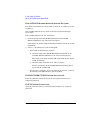
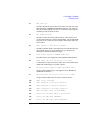
HIGH VOLTAGE SHOCK HAZARD
The Agilent 4155B/4156B/41501B can force dangerous voltages (200 V for HPSMU, and
100 V for HRSMU and MPSMU) at the force, guard, and sense terminals. To prevent
electric shock hazard, the following safety precautions must be observed during the use of
the Agilent 4155B/4156B/41501B.
Use a three-conductor ac power cable to connect cabinet (if used) and
Agilent 4155B/4156B/41501B to an electric ground (safety ground).
If you do not use Agilent 16442A Test Fixture, make sure to connect the INTLK terminal
to a switch that turns off when the shielding box access door is opened.
Confirm periodically that INTLK function works normally.
Before touching the connections of the force, guard, and sense terminals, turn the
Agilent 4155B/4156B/41501B off and discharge any capacitors whenever possible. If you
do not turn the Agilent 4155B/4156B/41501B off, complete "all" of the following items,
regardless of any Agilent 4155B/4156B/41501B settings.
Terminate measurement by pressing Stop key, confim that the MEASUREMENT
indicator is not lit.
Deactivate standby mode (if used) by pressing Standby key, confim that the Standby
indicator is not lit.
Confirm that the HIGH VOLTAGE indicator is not lit.
Open the shielding box access door (open the INTLK terminal).
Discharge any capacitors if the capacitance is connected to an SMU.
Warn workers in the vicinity of the Agilent 4155B/4156B/41501B about dangerous
conditions.
Agilent 4155B/4156B User’s Guide Vol.1, Edition 4
9
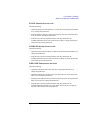
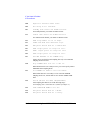
!"#
$%&'()*+,-./012(&'()%3'()*+,-.
012456789:
;<5=>?@A"BCDEFGHIJBKLMNOPQ8R@
ST"UVWXLYZ[O
L\]?:;<@
/^_`abcdIeabcd=:Rfgh
LYZ?:*+iXjklbmnglbopL\q?:;<@
mnglbop<iXjklbrLsRt
uvwxyLzf?:;<5{|:op;<L}[?@
mnglb~5{=:;<L
?:;<@
\q9:
"UL:;<@
din5\q89OR:*+dinL"?:;<@
"ULR*+IJBLO?:;<@
'§¨L©[(ª')3ª(ªvwm«Vn5¬[OR:;<L
?:
;<@
'®1¯°L©['®1¯°m«Vn5¬[OR:;<L
?:;<@
¢"#±²$%u³%0´xw³ª4m«Vn5¬[OR:;<L
?:;<@
iX`klbrLsµ:¶uvwxyLzf?:·;<@
din5'()\q89OR:¸dinL"?:;<@
[O¡¢"# ! ?:£¤L¥¦?:;<@
10
Agilent 4155B/4156B User’s Guide Vol.1, Edition 4
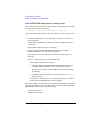
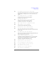
PRECAUTIONS POUR COMMOTION A HAUTE TENSION
Une tension dangereuse (max. ± pour HPSMU; 200 Vdc, max. ± pour HPSMU ou HRSMU;
100 Vdc) émanant du dispositif Agilent 4155B/4156B/41501B peut être sortie aux bornes de
force, d'appareil de protection ou de détection. Les précautions suivantes doivent être obserées
contre commotion électrique accidentelle:
Mettre à la terre le dispositif Agilent 4155B/4156B/41501B au moyen du câble d'alim
entation tripolaire.
En cas de hors service du dispositif d'essai, FIXTURE Agilent 16442A, connecter les
bornes de verrouillage (INTLK) de façon à ce que soit ouverte lorsque le couvercle de la
boîte de blindage est ouvert.
Essayer périodiquement le fonctionnement normal de verrouillage.
Avant de toucher la partie connexion à partir des bornes de force, d'appareil de protection
et de détection, mettre hors tension le dispositif Agilent 4155B/4156B/41501B.
Et, en cas de condensateurs connectés au circuit de mesure, décharger ces condensateurs.
Lorsque l'alimentation n'est pas mise hors tension, les 4 instructions suivantes doivent être
exécutées:
Finir la mésure en appuyant sur la touche "STOP"; verifier que l'indicateur
"MEASUREMENT" n'est pas allumé.
Désactiver le mode "Standby" (si utilise) en appuyant sur la touche "Standby";
verifier que l'indicateur "Standby" n'est pas allumé.
S'assurer que soit allumé l'indicateur d'alarme de la haute tension.
Ouvrir le convercle de la boîte de blindage (Ouvrir les bornes de verrouillage).
En cas de condensateurs connectés à SMU, décharger les condensateurs.
Alerter d'autres personnes autour de vous contre le danger de haute tension.
Agilent 4155B/4156B User’s Guide Vol.1, Edition 4
11
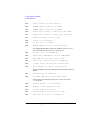
Achtung! Gefährliche Spannung
Von den Geräten Agilent 4155B/4156B/41501B können Spannungen an den Anschlüssen "Force,
Guard und Sense" von bis zu 200 V ausgehen. Um elektrischem Schlag vorzubeugen, ist bei der
Benützung der Geräte Agilent 4155B/4156B/41501B folgendes zu beachten:
Erden Sie das Kabinett (falls verwendet) sowie die Geräte Agilent 4155B/4156B/41501B
mittels dreiadriger Netzleitungen.
Wenn die Meßfassung, Agilent 16442A, zwar angeschlossen, jedoch nicht verwendet wird,
schließen Sie die Verriegelungsklemme (INTLK) so an, daß bei geöffnetem Deckel die
Stromzuführung zu Agilent 16442A auf jeden Fall unterbrochen wird.
Vergewissern Sie sich regelmäßig daß die Verriegelungsfunktion korrekt arbeitet.
Schalten Sie die Geräte Agilent 4155B/4156B/41501B aus, und entladen Sie alle Kapazitäten
bevor Sie die Anschlüsse "Force, Guard und Sense" berühren. Falls Sie die Geräte
Agilent 4155B/4156B/41501B nicht ausschalten, führen Sie unabhängig von den
Geräteeinstellungen folgende Schritte durch:
Beenden Sie die gegenwärtige Messung durch Drücken der Stop Taste (die
MEASUREMENT Leuchtdiode erlischt).
Deaktivieren Sie den Standby Modus (falls verwendet) durch Drücken der Standby Taste
(die Standby Leuchtdiode erlischt).
Vergewissern Sie sich daß die Hochspannungswarnlampe erloschen ist.
Öffnen Sie den Deckel der Meßfassung Agilent 16442A (die Verriegelungsklemme
(INTLK) öffnen).
Entladen Sie alle an SMUs angeschlossenen Kondensatoren (falls vorhanden).
Informieren Sie Personen in unmittelbarer Nähe der Geräte Agilent 4155B/4156B/41501B über
die Gefährlichkeit der bestehenden Hochspannung, und sichern Sie den Zugang zum Prüfplatz
zum Schutz Dritter.
12
Agilent 4155B/4156B User’s Guide Vol.1, Edition 4
In This Manual
This manual provides information and instructions for installation, file operation,
printer/plotter function, and what unrelated to the measurement and analysis, and
consists of the following chapters. For the information about the measurement and
analysis, refer to User's Guide Measurement and Analysis.
•
Introducing the 4155B/4156B
This chapter describes overview of the 4155B/4156B.
•
Installation
This chapter describes how to install the 4155B/4156B, accessories, and
peripherals.
•
File Operations
This chapter describes how to store or load the 4155B/4156B setup and
measurement data.
•
Print/Plot Function
This chapter provides information about the print/plot function.
•
System Screen Organization
This chapter provides information about the user interface displayed on the
4155B/4156B screen by pressing the System key.
•
External Keyboard
This chapter provides softkey maps and information about using an external
keyboard (furnished with the 4155B/4156B).
•
Initial Settings
This chapter provides information about user defined initial settings and default
initial settings.
•
Specifications
•
Accessories and Options
•
If You Have A Problem
Agilent 4155B/4156B User’s Guide Vol.1, Edition 4
13
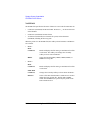
Other Manuals
The following Agilent 4155B/4156B manuals are also available:
•
User's Guide Measurement and Analysis
This manual provides information about measurement and analysis by using the
4155B/4156B, and consists of the following chapters:
•
•
Measurement Units
•
Measurement Mode
•
Measurement Functions
•
Making Measurement
•
Analyzing Measurement Results
•
Screen Organization
•
Data Variables and Analysis Function
•
If You Have A Problem
Quick Start Guide
This manual is mainly for beginners and provides brief instructions about using
the 4155B/4156B.
•
Programmer's Guide
This manual provides information about controlling the 4155B/4156B by
remote control command via GPIB interface and Instrument BASIC, and
consists of the following chapters:
•
•
Using Instrument BASIC
•
4155B/4156B SCPI Programming
•
4155B/4156B FLEX Programming
•
Running 4145A/B Program Directly on the 4155B/4156B
•
ASP-Like IBASIC Programming
SCPI Command Reference
This manual is a complete reference of the 4155B/4156B SCPI (Standard
Commands for Programmable Instruments) Command Set.
14
Agilent 4155B/4156B User’s Guide Vol.1, Edition 4
•
GPIB Command Reference
This manual is a complete reference of the 4155B/4156B FLEX Command Set
and the 4145B Syntax Command Set.
•
Sample Application Programs Guide Book
This manual introduces application measurement examples using the
4155B/4156B and the sample application program disk furnished with the
4155B/4156B.
•
VXIplug&play Driver User's Guide
This manual provides information about VXIplug&play driver for the
4155B/4156B. This manual also introduces an application measurement
example using the 4155B/4156B and the VXIplug&play driver.
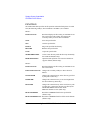
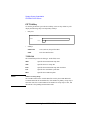
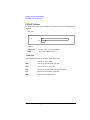
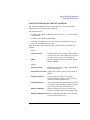
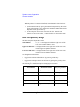
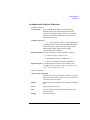
Text Conventions
The following text conventions are used in this manual:
Screen Text
Represents text that appears on screen of the 4155B/4156B.
Italic
Refers to a related document, or is used for emphasis.
Agilent 4155B/4156B User’s Guide Vol.1, Edition 4
15
16
Agilent 4155B/4156B User’s Guide Vol.1, Edition 4
Contents
1. Introducing the 4155B/4156B
Overview . . . . . . . . . . . . . . . . . . . . . . . . . . . . . . . . . . . . . . . . . . . . . . . . . . . . . . . . 1-4
Measurement Unit Configurations . . . . . . . . . . . . . . . . . . . . . . . . . . . . . . . . . . . . 1-6
Front View of the 4155B/4156B . . . . . . . . . . . . . . . . . . . . . . . . . . . . . . . . . . . . . . 1-7
Rear View of the 4155B/4156B . . . . . . . . . . . . . . . . . . . . . . . . . . . . . . . . . . . . . 1-11
. . . . . . . . . . . . . . . . . . . . . . . . . . . . . . . . . . . . . . . . . . . . . . . . . . . . . . . . . . . 1-12
. . . . . . . . . . . . . . . . . . . . . . . . . . . . . . . . . . . . . . . . . . . . . . . . . . . . . . . . . . . 1-13
Front and Rear View of the 41501A/B . . . . . . . . . . . . . . . . . . . . . . . . . . . . . . . . 1-14
. . . . . . . . . . . . . . . . . . . . . . . . . . . . . . . . . . . . . . . . . . . . . . . . . . . . . . . . . . . 1-15
2. Installation
. . . . . . . . . . . . . . . . . . . . . . . . . . . . . . . . . . . . . . . . . . . . . . . . . . . . . . . . . . . . 2-2
Requirements . . . . . . . . . . . . . . . . . . . . . . . . . . . . . . . . . . . . . . . . . . . . . . . . . . . . 2-3
Power Requirements . . . . . . . . . . . . . . . . . . . . . . . . . . . . . . . . . . . . . . . . . . . . . 2-3
Power Cable . . . . . . . . . . . . . . . . . . . . . . . . . . . . . . . . . . . . . . . . . . . . . . . . . . . . 2-3
Line Fuse and Line Voltage Selector for the 41501A . . . . . . . . . . . . . . . . . . . . 2-5
Ventilation Requirements . . . . . . . . . . . . . . . . . . . . . . . . . . . . . . . . . . . . . . . . . 2-5
Operating Environment . . . . . . . . . . . . . . . . . . . . . . . . . . . . . . . . . . . . . . . . . . . 2-6
Storaging/Shipping Environment . . . . . . . . . . . . . . . . . . . . . . . . . . . . . . . . . . . 2-6
Cleaning . . . . . . . . . . . . . . . . . . . . . . . . . . . . . . . . . . . . . . . . . . . . . . . . . . . . . . . 2-6
Inspection . . . . . . . . . . . . . . . . . . . . . . . . . . . . . . . . . . . . . . . . . . . . . . . . . . . . . . . 2-7
To Inspect the 4155B/4156B and Accessories . . . . . . . . . . . . . . . . . . . . . . . . . 2-7
To Check the 4155B/4156B Operation . . . . . . . . . . . . . . . . . . . . . . . . . . . . . . . 2-8
To Execute Diagnostics and Calibration . . . . . . . . . . . . . . . . . . . . . . . . . . . . . 2-10
Connecting the 41501A/B SMU/Pulse Generator Expander . . . . . . . . . . . . . . . 2-11
Agilent 4155B/4156B User’s Guide Vol.1, Edition 4
Contents - 1
Contents
Installing Accessories . . . . . . . . . . . . . . . . . . . . . . . . . . . . . . . . . . . . . . . . . . . . .
To Install the 16442A Test Fixture . . . . . . . . . . . . . . . . . . . . . . . . . . . . . . . . .
To Install the 16441A R-Box . . . . . . . . . . . . . . . . . . . . . . . . . . . . . . . . . . . . .
To Install the 16440A SMU/Pulse Generator Selector . . . . . . . . . . . . . . . . . .
To Connect the 16440A Selector to the 4155B/4156B . . . . . . . . . . . . . . . . . .
To Connect the Measurement Cable to the Connector Plate . . . . . . . . . . . . . .
........................................................
2-12
2-13
2-18
2-20
2-26
2-28
2-30
Mounting Connectors . . . . . . . . . . . . . . . . . . . . . . . . . . . . . . . . . . . . . . . . . . . . .
To Make an Interlock Circuit . . . . . . . . . . . . . . . . . . . . . . . . . . . . . . . . . . . . .
To Connect the GNDU Output . . . . . . . . . . . . . . . . . . . . . . . . . . . . . . . . . . . .
To Connect the SMU Output . . . . . . . . . . . . . . . . . . . . . . . . . . . . . . . . . . . . . .
To Connect the VSU/VMU/PGU Outputs . . . . . . . . . . . . . . . . . . . . . . . . . . .
2-31
2-33
2-37
2-38
2-40
Connecting Instruments or Peripherals . . . . . . . . . . . . . . . . . . . . . . . . . . . . . . . .
To Connect GPIB Instruments or Peripherals . . . . . . . . . . . . . . . . . . . . . . . . .
To Connect Parallel Peripherals . . . . . . . . . . . . . . . . . . . . . . . . . . . . . . . . . . .
To Connect to a LAN . . . . . . . . . . . . . . . . . . . . . . . . . . . . . . . . . . . . . . . . . . .
2-41
2-41
2-42
2-43
3. File Operations
Selecting a Mass Storage Device . . . . . . . . . . . . . . . . . . . . . . . . . . . . . . . . . . . . . 3-4
Listing a File Catalog . . . . . . . . . . . . . . . . . . . . . . . . . . . . . . . . . . . . . . . . . . . . . . 3-5
Storing Setup or Results Data . . . . . . . . . . . . . . . . . . . . . . . . . . . . . . . . . . . . . . . . 3-6
Storing Results Data in Spreadsheet Format . . . . . . . . . . . . . . . . . . . . . . . . . . . . 3-8
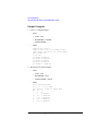
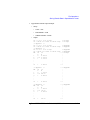
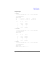
Output Format for the ASCII SAVE Function . . . . . . . . . . . . . . . . . . . . . . . . 3-10
Output Examples . . . . . . . . . . . . . . . . . . . . . . . . . . . . . . . . . . . . . . . . . . . . . . . 3-12
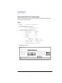
Loading Setup or Results Data . . . . . . . . . . . . . . . . . . . . . . . . . . . . . . . . . . . . . . 3-14
Changing a File Name . . . . . . . . . . . . . . . . . . . . . . . . . . . . . . . . . . . . . . . . . . . . 3-16
Removing a File/Directory . . . . . . . . . . . . . . . . . . . . . . . . . . . . . . . . . . . . . . . . . 3-17
Copying a File . . . . . . . . . . . . . . . . . . . . . . . . . . . . . . . . . . . . . . . . . . . . . . . . . . 3-18
Contents - 2
Agilent 4155B/4156B User’s Guide Vol.1, Edition 4
Contents
Creating a Directory on a Network File System . . . . . . . . . . . . . . . . . . . . . . . . . 3-20
Changing the Working Directory . . . . . . . . . . . . . . . . . . . . . . . . . . . . . . . . . . . . 3-21
Initializing a Diskette . . . . . . . . . . . . . . . . . . . . . . . . . . . . . . . . . . . . . . . . . . . . . 3-22
Backing Up a Diskette . . . . . . . . . . . . . . . . . . . . . . . . . . . . . . . . . . . . . . . . . . . . 3-23
4. Print/Plot Function
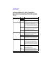
Output Formats . . . . . . . . . . . . . . . . . . . . . . . . . . . . . . . . . . . . . . . . . . . . . . . . . . . 4-3
Differences Between PCL, HR PCL and HP-GL . . . . . . . . . . . . . . . . . . . . . . . 4-4
Output Resolution . . . . . . . . . . . . . . . . . . . . . . . . . . . . . . . . . . . . . . . . . . . . . . . 4-5
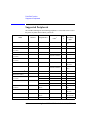
Supported Peripherals . . . . . . . . . . . . . . . . . . . . . . . . . . . . . . . . . . . . . . . . . . . . . . 4-6
Connecting Peripherals . . . . . . . . . . . . . . . . . . . . . . . . . . . . . . . . . . . . . . . . . . . 4-7
Printing/Plotting Screen Images . . . . . . . . . . . . . . . . . . . . . . . . . . . . . . . . . . . . . . 4-8
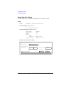
Printing/Plotting Setup Data Lists . . . . . . . . . . . . . . . . . . . . . . . . . . . . . . . . . . . . 4-11
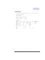
Printing/Plotting Measurement Data Lists . . . . . . . . . . . . . . . . . . . . . . . . . . . . . 4-14
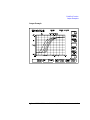
Printing/Plotting Measurement Data Graphs . . . . . . . . . . . . . . . . . . . . . . . . . . . 4-17
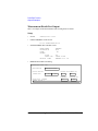
Saving Screen Images . . . . . . . . . . . . . . . . . . . . . . . . . . . . . . . . . . . . . . . . . . . . . 4-21
Saving Setup Data Lists . . . . . . . . . . . . . . . . . . . . . . . . . . . . . . . . . . . . . . . . . . . 4-24
Saving Measurement Data Lists . . . . . . . . . . . . . . . . . . . . . . . . . . . . . . . . . . . . . 4-28
Saving Measurement Data Graphs . . . . . . . . . . . . . . . . . . . . . . . . . . . . . . . . . . . 4-32
Output Examples . . . . . . . . . . . . . . . . . . . . . . . . . . . . . . . . . . . . . . . . . . . . . . . . . 4-37
Screen Dump Output . . . . . . . . . . . . . . . . . . . . . . . . . . . . . . . . . . . . . . . . . . . . 4-38
Setup Data List Output . . . . . . . . . . . . . . . . . . . . . . . . . . . . . . . . . . . . . . . . . . 4-40
Measurement Result List Output . . . . . . . . . . . . . . . . . . . . . . . . . . . . . . . . . . . 4-42
Measurement Result Graph Output . . . . . . . . . . . . . . . . . . . . . . . . . . . . . . . . . 4-44
Agilent 4155B/4156B User’s Guide Vol.1, Edition 4
Contents - 3
Contents
5. System Screen Organization
Screen Structure . . . . . . . . . . . . . . . . . . . . . . . . . . . . . . . . . . . . . . . . . . . . . . . . . . 5-3
SYSTEM Screen Group . . . . . . . . . . . . . . . . . . . . . . . . . . . . . . . . . . . . . . . . . . . . 5-5
SYSTEM: FILER screen . . . . . . . . . . . . . . . . . . . . . . . . . . . . . . . . . . . . . . . . . . . 5-6
SYSTEM: MISCELLANEOUS screen . . . . . . . . . . . . . . . . . . . . . . . . . . . . . . . 5-22
SYSTEM: CONFIGURATION screen . . . . . . . . . . . . . . . . . . . . . . . . . . . . . . . . 5-28
SYSTEM: SELF-CALIBRATION/DIAGNOSTICS screen . . . . . . . . . . . . . . . 5-29
SYSTEM: PRINT/PLOT SETUP screen . . . . . . . . . . . . . . . . . . . . . . . . . . . . . . 5-32
SYSTEM: COLOR SETUP screen . . . . . . . . . . . . . . . . . . . . . . . . . . . . . . . . . . 5-36
Screen Operation . . . . . . . . . . . . . . . . . . . . . . . . . . . . . . . . . . . . . . . . . . . . . . . .
Data Input or Edit . . . . . . . . . . . . . . . . . . . . . . . . . . . . . . . . . . . . . . . . . . . . . .
Blue front-panel key usage . . . . . . . . . . . . . . . . . . . . . . . . . . . . . . . . . . . . . . .
Green front-panel key usage . . . . . . . . . . . . . . . . . . . . . . . . . . . . . . . . . . . . . .
Edit front-panel keys . . . . . . . . . . . . . . . . . . . . . . . . . . . . . . . . . . . . . . . . . . . .
5-39
5-39
5-40
5-41
5-42
Status Indicators . . . . . . . . . . . . . . . . . . . . . . . . . . . . . . . . . . . . . . . . . . . . . . . . . 5-43
6. External Keyboard
7. Initial Settings
8. Specifications
9. Accessories and Options
10. If You Have A Problem
Contents - 4
Agilent 4155B/4156B User’s Guide Vol.1, Edition 4
1
Introducing the 4155B/4156B
Agilent 4155B/4156B User’s Guide Vol.1, Edition 4
Introducing the 4155B/4156B
Agilent 4155B/4156B is an electronic instrument for measuring and analyzing the
characteristics of semiconductor devices. This one instrument allows you to perform
both measurement and analysis of measurement results.
Following is summary of Agilent 4155B/4156B features.
•
Measurement Capabilities
The 4155B/4156B has four highly accurate source/monitor units (SMUs), two
voltage source units (VSUs), and two voltage measurement units (VMUs). The
4156B is designed for Kelvin connections and has high-resolution SMUs
(HRSMUs), so the 4156B is especially suited for low resistance and low current
measurements. You can measure voltage values with a resolution of 1 V by
using the differential measurement mode of VMUs.
The 4155B/4156B can perform two types of measurements, sweep measurement
and sampling measurement. The 4155B/4156B also provides knob sweep
measurement function for quick sweep measurements executed by rotating the
rotary knob on the front panel.
The 4155B/4156B can perform stress testing. That is, can force a specified dc
voltage or current for the specified duration. Also, you can force ac stress by
using pulse generator units (PGUs), which are installed in Agilent 41501A/B
SMU/Pulse Generator Expander.
•
Analysis Function
The 4155B/4156B provides a marker and two lines for analyzing the
measurement results. The 4155B/4156B also provides the automatic analysis
function which moves marker and lines at desired location and displays desired
calculation results automatically after measurement is completed.
•
Data storing
The 4155B/4156B allows you to store measurement setup information,
measurement data, and instrument setting information on a 3.5-inch diskette
using the built-in flexible disk drive, or on a NFS server via LAN.
The allowable disk formats are MS-DOS and HP LIF.
You can also use internal memory for temporary data storage. You can save up
to four files in internal memory. You can quickly move information between the
internal memory and the 4155B/4156B working memory.
1-2
Agilent 4155B/4156B User’s Guide Vol.1, Edition 4
Introducing the 4155B/4156B
•
Printing and plotting
The 4155B/4156B allows you to print the setup data, measurement results and
screen images on a printer or plotter that is connected to the 4155B/4156B via
GPIB interface, or parallel I/O interface. The 4155B/4156B can also store a
TIFF, PCL, or HP-GL file.
You can also use a remote printer via LAN to make hardcopies.
•
Remote control
The 4155B/4156B can be controlled by an external controller via GPIB by using
remote control commands. The 4155B/4156B provides the following command
sets, so you can select the command set suitable for your application.
•
4155B/4156B SCPI (Standard Commands for Programmable Instruments)
command set
•
4155B/4156B FLEX (Fast Language for Execution) command set
•
4145B syntax command set
Also the 4155B/4156B has internal Instrument BASIC, so you can develop and
execute measurement programs by using the 4155B/4156B only, without using
an external controller.
Agilent 4155B/4156B User’s Guide Vol.1, Edition 4
1-3
Introducing the 4155B/4156B
Overview
Overview
The 4155B/4156B is a box type electronic measurement instrument with LCD
display, flexible disk drive, operation keys, and interface connectors.
•
Keyboard
You can connect a keyboard to the 4155B/4156B. So, you can operate this
instrument by using a keyboard or the front-panel keys.
•
Agilent 41501A/B SMU/Pulse Generator Expander
The 41501A/B SMU and Pulse Generator Expander contains pulse generator
units (PGUs) and additional SMUs. The 41501A/B is attached to and controlled
by the 4155B/4156B.
•
Test Fixture
Agilent 16442A is the test fixture for the 4155B/4156B. You can mount your
device under test (DUT) on the 16442A, and measure the device characteristics.
•
Resistor Box
Agilent 16441A R-Box contains accurate 10 kW, 100 kW, and 1 MW resistors,
and connection of these resistors is controlled by the 4155B/4156B. The 16441A
is used to measure negative resistance and to prevent DUT damage when
performing breakdown measurements.
1-4
Agilent 4155B/4156B User’s Guide Vol.1, Edition 4
Introducing the 4155B/4156B
Overview
•
SMU/PGU Selector
Agilent 16440A SMU/Pulse Generator Selector contains two switching circuits
to connect the DUT to either an SMU or PGU. You can attach another 16440A
to add two more switching circuits.
Agilent 4155B/4156B User’s Guide Vol.1, Edition 4
1-5
Introducing the 4155B/4156B
Measurement Unit Configurations
Measurement Unit Configurations
Agilent 4155B, 4156B, and 41501A/B are frames that contain the measurement
units. The measurement units are installed before the product is shipped from
factory. User cannot reconfigure the installed units.
•
•
Agilent 4155B configuration:
•
four medium power source monitor units (MPSMUs).
•
two voltage source units (VSUs).
•
two voltage monitor units (VMUs).
Agilent 4156B configuration:
•
four high resolution source monitor units (HRSMUs).
•
two voltage source units (VSUs).
•
two voltage monitor units (VMUs).
The 4156B has higher measurement resolution. For details about measurement
range and resolution, refer to "Measurement Units" in the 4155B/4156B User's
Guide: Measurement and Analysis.
•
Agilent 41501A/B configuration:
The 41501A/B is attached to the 4155B/4156B at your site. See Chapter 2,
“Installation,” on how to install the 41501A/B.
The 41501A/B contains a ground unit (GNDU). In addition, you specify an
option number according to desired units as follows:
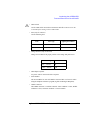
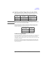
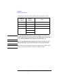
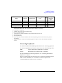
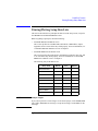
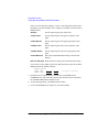
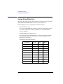
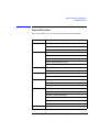
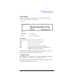
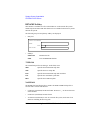
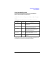
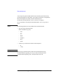
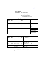
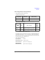
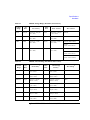
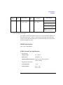
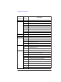
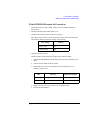
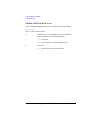
Table 1-1
Configuration of the 41501A/B
Agilent 41501A/B Option
Unit
402
One GNDU
yes
Two PGUs
yes
410
yes
412
yes
yes
yes
Two MPSMUs
One HPSMU a
420
yes
yes
yes
yes
422
yes
yes
a. HPSMU: high power source monitor unit
1-6
Agilent 4155B/4156B User’s Guide Vol.1, Edition 4
Introducing the 4155B/4156B
Front View of the 4155B/4156B
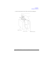
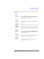
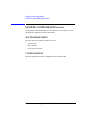
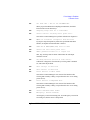
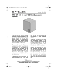
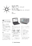
Front View of the 4155B/4156B
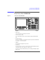
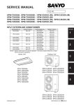
Figure 1-1
Front View of the 4155B/4156B
•
LINE switch
Use the LINE switch to turn analyzer on and off.
•
Flexible disk drive (FDD)
Use 3.5 inch diskette to load or store the analyzer settings and measurement
data.
•
Keyboard connector
You can use an IBM PC/AT compatible keyboard to operate the 4155B/4156B.
See Chapter 6, “External Keyboard.”
•
Help key
Pressing Help key displays the help screens.
•
Plot/Print key
Pressing Print/Plot key prints the setup information and measurement results to
your plotter, printer, or file, TIFF, PCL, or HP-GL file.
If you press green key and Print/Plot key, the screen image is dumped to plotter,
printer, or file.
Agilent 4155B/4156B User’s Guide Vol.1, Edition 4
1-7
Introducing the 4155B/4156B
Front View of the 4155B/4156B
•
PAGE CONTROL key group
Page Control keys are used to change the display screens.
•
Chan key
Moves to CHANNELS screen group. You define channels,
user functions, and user variables.
Meas key
Moves to MEASURE screen group. You set the output
parameters, measurement parameters, and so on.
Display key
Moves to DISPLAY screen group. You set the result display
format, auto analysis definitions, and so on.
Graph/List key
Moves to GRAPH/LIST screen group. This softkey toggles
between GRAPH and LIST screens.
Stress key
Moves to STRESS screen group. You define the stress
channels, set the stress parameters, and monitor the stress
forcing.
System key
Moves to SYSTEM screen group. You operate on diskette
files, set up plotting and printing environment, define colors
of the display, and so on.
MARKER/CURSOR key group
Rotary knob and arrow keys of the Marker/Cursor key group are used to move
the marker and cursor.
Rotary knob
Moves the marker, or increases or decreases setup value.
Arrow keys
Up, Down, Left, and Right. Moves field pointer or cursor.
Fast key
Moves the marker or cursor faster. When you rotate the
rotary knob or press the arrow keys with holding Fast key
down, the marker or cursor moves faster.
1-8
Agilent 4155B/4156B User’s Guide Vol.1, Edition 4
Introducing the 4155B/4156B
Front View of the 4155B/4156B
•
MEASUREMENT key group
Measurement keys control the measurement, stress, and integration time.
Single key
Executes the measurement once, then returns to the idle
state (or standby state if standby is enabled for the channel)
after the measurement is finished. Measurement data is
updated, so data of previous measurement is lost. Pressing
the green key, then Single key starts knob sweep
measurement.
Repeat key
Starts and repeats the measurement continuously.
Measurement data is updated, so data of previous
measurement is lost. To stop the measurement, press Stop
key.
Append key
Executes the measurement once, then returns to idle state
(or standby state if standby is enabled for the channel) after
measurement is finished. Measurement data is appended to
data of previous measurement.
Stop key
Stops the measurement or stress. Standby enabled channels
return to standby state, and other channels return to idle
state.
Standby key
Toggles between the standby enabled (Standby indicator is
lit) and disabled states. If Standby indicator is lit, then
STBY ON channels change to standby state (instead of idle
state) when measurement or stress finishes. Stop key has no
affect on standby state.
Stress key
Forces the specified stress. The guide around this key
prevents you from accidently pressing the Stress key.
Short,
Medium, and
Long keys
•
Sets the integration time to SHORT, MEDIUM, or LONG,
respectively.
MEASUREMENT indicator
This indicator lights when the 4155B/4156B is in the measurement state.
•
HIGH VOLTAGE indicator
This indicator lights when a unit forces more than 40 V.
Agilent 4155B/4156B User’s Guide Vol.1, Edition 4
1-9
Introducing the 4155B/4156B
Front View of the 4155B/4156B
•
Standby indicator
This indicator lights when the 4155B/4156B is standby enabled, which means
that the channels that are standby enabled (STBY ON) will return to the standby
state after the measurement is finished.
•
IBASIC key group
IBASIC keys control the IBASIC program execution.
•
Run key
Starts the IBASIC program that is in memory. The indicator
is on during program execution.
Pause key
Pauses the IBASIC program execution.
Display key
Toggles between the IBASIC screen and measurement
screen.
Run indicator
When an IBASIC program is running, this indicator lights.
•
ENTRY key group
You enter or modify data such as output values, comments, and variable names.
Character keys
Are used to enter alphanumeric and special characters.
Enter key
After you enter desired characters into the data entry field,
press this key. The characters are entered at the field pointer
location. Also, you can use the green key to calculate the
value of the data entry field. For example, if you press 4 * 6
green key and Enter key, the result (24) appears.
Blue key
Changes entry mode to blue-key shift mode, and lights the
indicator. In this mode, you can enter the blue characters
that are printed above the keys. Pressing blue key again
changes to normal mode. Indicator turns off.
Green key
Changes entry mode to green-key shift mode. This mode is
effective for the next pressed key, then changes back to
normal mode.
Edit keys
Are used to edit the characters in the data entry field.
User File keys
Are used to operate quickly on a file in diskette, internal
memory or a directory on a NFS server. Pressing Save key
moves into the filer's SAVE function, and pressing Get key
moves into the filer's GET function.
1-10
Agilent 4155B/4156B User’s Guide Vol.1, Edition 4
Introducing the 4155B/4156B
Rear View of the 4155B/4156B
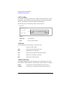
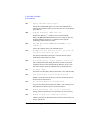
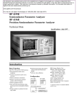
Rear View of the 4155B/4156B
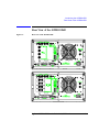
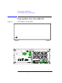
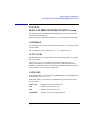
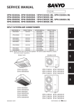
Figure 1-2
Rear View of the 4155B/4156B
Agilent 4155B/4156B User’s Guide Vol.1, Edition 4
1-11
Introducing the 4155B/4156B
Rear View of the 4155B/4156B
•
To R-Box terminal
"To R-Box" terminal is a 10-pin connector. To use R-Box, connect this terminal
to control terminal of Agilent 16441A R-Box.
•
VSU terminals
VSU output terminals are BNC connectors. To use VSUs, connect these
terminals to VSU terminals of Agilent 16442A or connector plate.
•
VMU terminals
VMU input terminals are BNC connectors. To use VMUs, connect these
terminals to VMU terminals of the 16442A or connector plate.
•
SMU terminals
The 4155B has four triaxial connectors. The 4156B has eight triaxial connectors,
and you can use Kelvin connections. When you use the 16442A test fixture and
Kelvin connections, up to 3 SMUs can be connected to the 16442A test fixture.
•
Circuit Common (
) and Frame ground (
) terminals
For floating measurement, remove the shorting bar (Agilent part number
5000-4206).
WARNING
Do not float the Circuit Common terminal at voltages greater than ±42 V
referenced to frame ground. Failure to heed this warning may result in damage
to Agilent 4155B/4156B.
•
To Expander Box Interface
When you use Agilent 41501A/B, you insert the board for the 41501A/B into
this interface.
•
Zero Check terminal
Ground reference point of the 4155B/4156B.
•
Serial number
You need this serial number when using the telephone assistance program
(Agilent Technologies HelpLine).
1-12
Agilent 4155B/4156B User’s Guide Vol.1, Edition 4
Introducing the 4155B/4156B
Rear View of the 4155B/4156B
•
Intlk terminal
Used in conjunction with interlock function of the 4155B/4156B. If the Intlk
terminal is open, maximum SMU output is limited to 40 V. Be sure to connect
this terminal to the 16442A test fixture or connector plate before performing
measurement. If you use connector plate, you must install interlock circuit. For
details on how to install the interlock circuit, see “To Make an Interlock Circuit”
in Chapter 2.
WARNING
Dangerous voltage of up to the maximum voltage of SMUs may be present at
force, guard, and sense terminals if the interlock terminal is shorted.
•
LAN interface
RJ45 connector. Ethernet IEEE 802.3 10BASE-T for a 10M bps CSMA/CD
local area network.
The 4155B/4156B can be a NFS cluster, and can use a remote printer to make
hardcopies.
•
Parallel interface
25-pin parallel I/O interface port for connecting peripheral such as a Centronics
parallel printer.
•
GPIB interface
Use Agilent 10833A/B/C/D GPIB cable.
•
Ext Trig terminals
Two BNC connectors: one for trigger input, and one for trigger output.
•
LINE input receptacle
AC power cable is connected to this receptacle.
Agilent 4155B/4156B User’s Guide Vol.1, Edition 4
1-13
Introducing the 4155B/4156B
Front and Rear View of the 41501A/B
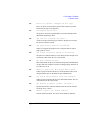
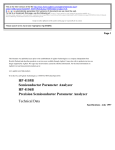
Front and Rear View of the 41501A/B
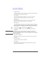
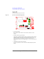
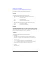
Figure 1-3
Front and Rear View of the 41501A
1-14
Agilent 4155B/4156B User’s Guide Vol.1, Edition 4
Introducing the 4155B/4156B
Front and Rear View of the 41501A/B
•
LINE switch
Use the LINE switch to turn the 41501A/B on and off. You must turn on the
41501A/B before turning on the 4155B/4156B.
•
Fuse (only for 41501A)
Use the following fuse:
Line
•
Fuse type
Agilent part number
100/120 Vac
UL/CSA T 8A, 250 Vac
2110-0383
220/240 Vac
UL/CSA T 4A, 250 Vac
2110-0014
Voltage Selector (only for 41501A)
Voltage selector must be in proper position. Line voltage and position are:
Line Voltage
•
Position
90 — 132 Vac
left
198 — 264 Vac
right
LINE input receptacle
AC power cable is connected to this receptacle.
•
Serial number
The 41501A/B has its own serial number. You need this serial number when
using the telephone assistance program (Agilent Technologies HelpLine).
•
GNDU connector
The GNDU connector is a triaxial connector: inner conductor is sense, middle
conductor is force, and outer conductor is circuit common.
Agilent 4155B/4156B User’s Guide Vol.1, Edition 4
1-15
Introducing the 4155B/4156B
Front and Rear View of the 41501A/B
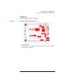
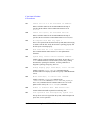
Option 402
The 41501A/B Option 402 has two PGUs.
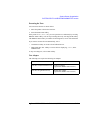
Figure 1-4
Rear View of the 41501A/B Option 402
•
PGU output terminals
BNC connectors. Inner conductor is force and outer conductor is circuit
common.
•
Ext Pulse Generator Trig Out terminal
Trigger pulses synchronized with PGU pulses are output. This trigger is used to
synchronize the PGU pulse outputs with external pulse generators. You cannot
change the parameters of this trigger. For details about PGU trigger, see
"Measurement Functions" in the 4155B/4156B User's Guide: Measurement and
Analysis.
•
To SMU/Pulse Generator Selector Interface
D-SUB 15-pin connector is used to control the 16440A SMU/pulse generator
selector.
1-16
Agilent 4155B/4156B User’s Guide Vol.1, Edition 4
Introducing the 4155B/4156B
Front and Rear View of the 41501A/B
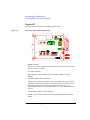
Option 410
The 41501A/B Option 410 has one HPSMU.
Figure 1-5
Rear View of the 41501A/B Option 410
•
HPSMU terminals
There are two triaxial connectors for Kelvin connections: one is for force and the
other is for sense. For SMU5.
Agilent 4155B/4156B User’s Guide Vol.1, Edition 4
1-17
Introducing the 4155B/4156B
Front and Rear View of the 41501A/B
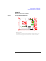
Option 412
The 41501A/B Option 412 has one HPSMU and two PGUs.
Figure 1-6
Rear View of the 41501A/B Option 412
•
HPSMU terminals
There are two triaxial connectors for Kelvin connections: one is for force and the
other is for sense. For SMU5.
•
PGU output terminals
BNC connectors. Inner conductor is force and outer conductor is circuit
common.
•
Ext Pulse Generator Trig Out terminal
Trigger pulses synchronized with PGU pulses are output. This trigger is used to
synchronize the PGU pulse outputs with external pulse generators. You cannot
change the parameters of this trigger. For details about PGU trigger, see
"Measurement Functions" in the 4155B/4156B User's Guide: Measurement and
Analysis.
•
To SMU/Pulse Generator Selector Interface
D-SUB 15-pin connector is used to control the 16440A SMU/pulse generator
selector.
1-18
Agilent 4155B/4156B User’s Guide Vol.1, Edition 4
Introducing the 4155B/4156B
Front and Rear View of the 41501A/B
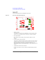
Option 420
The 41501A/B Option 420 has two MPSMUs.
Figure 1-7
Rear View of the 41501A/B Option 420
•
MPSMU terminals
Two MPSMUs are installed and each MPSMU has a triaxial connector. These
connectors are not designed for Kelvin connections. For SMU5 and SMU6.
Agilent 4155B/4156B User’s Guide Vol.1, Edition 4
1-19
Introducing the 4155B/4156B
Front and Rear View of the 41501A/B
Option 422
The 41501A/B Option 422 has two MPSMUs and two PGUs.
Figure 1-8
Rear View of the 41501A/B Option 422
•
MPSMU terminals
Two MPSMUs are installed and each MPSMU has a triaxial connector. These
connectors are not designed for Kelvin connections. For SMU5 and SMU6.
•
PGU output terminals
BNC connectors. Inner conductor is force and outer conductor is circuit
common.
•
Ext Pulse Generator Trig Out terminal
Trigger pulses synchronized with PGU pulses are output. This trigger is used to
synchronize the PGU pulse outputs with external pulse generators. You cannot
change the parameters of this trigger. For details about PGU trigger, see
"Measurement Functions" in the 4155B/4156B User's Guide: Measurement and
Analysis.
•
To SMU/Pulse Generator Selector Interface
D-SUB 15-pin connector is used to control the 16440A SMU/pulse generator
selector.
1-20
Agilent 4155B/4156B User’s Guide Vol.1, Edition 4
2
Installation
Agilent 4155B/4156B User’s Guide Vol.1, Edition 4
Installation
This chapter describes the requirements and procedures to install Agilent
4155B/4156B. It contains the following information:
WARNING
•
requirements
•
inspection
•
connecting the 41501A/B
•
installing accessories
•
mounting connectors
•
connecting peripherals
There are potentially hazardous voltages (200 V for HPSMU, and 100 V for
HRSMU and MPSMU) present at the Force, Guard, and Sense terminals of the
4155B/4156B. To prevent electrical shock, the following safety precautions
must be observed during the use of the 4155B/4156B.
•
Use a three-conductor ac power cable to connect the cabinet (if used) and
the 4155B/4156B to an electrical ground (safety ground).
•
If you do not use the 16442A test fixture, you must connect the Intlk
terminal to a switch that turns off when the shielding box access door is
opened.
•
Confirm periodically that the interlock function works normally.
•
Before touching the connections on the Force, Guard, and Sense
terminals, turn the 4155B/4156B off and discharge any capacitors. If you
do not turn the 4155B/4156B off, complete all of the following items,
regardless of the 4155B/4156B settings.
•
2-2
•
Terminate measurement by pressing Stop key, confirm that the
MEASUREMENT indicator is not lit.
•
Deactivate standby mode (if used) by pressing Standby key, confirm
that the Standby indicator is not lit.
•
Confirm that the HIGH VOLTAGE indicator is not lit.
•
Open the shielding box access door (open the Intlk terminal).
•
Discharge any capacitors connected to an SMU.
Warn persons working around the 4155B/4156B about dangerous
conditions.
Agilent 4155B/4156B User’s Guide Vol.1, Edition 4
Installation
Requirements
Requirements
This section contains information on:
•
•
•
•
•
•
•
power requirements
power cables
line fuse and line voltage selectors (for the 41501A)
ventilation requirements
operating environment
storaging/shipping environment
cleaning
Power Requirements
The 4155B/4156B can operate from any single-phase ac power source supplying 90
to 264 V at 47 to 63 Hz. The maximum power consumption is 450 VA for the
4155B/4156B/41501A, and 350 VA for the 41501B. For details, see Chapter 8.
Power Cable
CAUTION
Before applying ac line power to the 4155B/4156B or the 41501A/B, ensure that the
correct power cable is used.
In accordance with international safety standards, this instrument is equipped with a
three-prong power cable. When connected to an appropriate ac power outlet, this
cable grounds the instrument frame. The type of power cable shipped with each
instrument depends on the country of destination. Refer to the following table for
the Agilent part numbers of the power cables available.
If the plug on the cable does not fit the power outlet, or the cable is to be attached to
a terminal block, cut the cable at the plug end and re-wire it. This work should be
performed by a qualified electrician, observing all local electrical codes.
The color coding used in the cable will depend on the cable supplied. If a new plug
is to be connected, it must meet local safety requirements and include the following
features:
•
adequate load-carrying capacity (see Chapter 8)
•
ground connection
•
cable clamp
Agilent 4155B/4156B User’s Guide Vol.1, Edition 4
2-3
Installation
Requirements
WARNING
For protection from electrical shock, do not interrupt the power cable ground.
•
•
•
•
•
•
•
Plug: BS 1363/A,
250 V, 10 A
Cable: 8120-1351
Plug: NEMA 5-15P,
125 V, 10 A
Cable: 8120-1378
Plug: SR 107-2-D,
250 V, 10 A
Cable: 8120-2956
•
•
•
•
2-4
Plug: Argentine
Resolution 63, Annex
IV, 250 V, 10 A
Cable: 8120-6870
Plug: NEMA 6-15P,
250 V, 6 A
Cable: 8120-0698
•
•
•
•
•
•
•
•
Plug: AS 3112, 250 V,
10 A
Cable: 8120-1369
•
•
Plug: IEC 83-B1,
250 V, 10 A
Cable: 8120-4211
Plug: CEI 23-16, 250 V,
10 A
Cable: 8120-6978
•
•
•
Plug: CEE 7 Standard
Sheet VII, 250 V, 10 A
Cable: 8120-1689
Plug: SEV Type 12,
250 V, 10 A
Cable: 8120-2104
Plug: JIS C 8303,
125 V, 12 A
Cable: 8120-4753
Plug: GB 1002, 250 V,
10 A
Cable: 8120-8376
Agilent 4155B/4156B User’s Guide Vol.1, Edition 4
Installation
Requirements
Line Fuse and Line Voltage Selector for the 41501A
Before applying ac line power to the 41501A, verify that the correct line fuse is
installed in the fuse holder and the line voltage selector is set correctly.
Line
WARNING
Fuse Type
Agilent Part Number
100/120 Vac
UL/CSA T 8A, 250 Vac
2110-0383
220/240 Vac
UL/CSA T 4A, 250 Vac
2110-0014
Replace the line fuse only with the same type and rating. Do not use repaired
fuses, and do not short circuit the fuse holder.
The line voltage selector switch is set at the factory. Verify the voltage selector
setting before applying ac line power to the 41501A. The line voltage selector
switch is located on the rear panel of the 41501A
Line Voltage
Position
90 — 132 Vac
left
198 — 264 Vac
right
Ventilation Requirements
The 4155B/4156B has one cooling fan, and the 41501A/B has two cooling fans. To
ensure adequate airflow, make sure that there is sufficient clearance around the
cooling fans: 6 inches (150 mm) behind, 3 inches (70 mm) on the sides, and 0.5 inch
(12 mm) above and below.
If the airflow is restricted, the internal operating temperature will be higher. This
may reduce the instrument's reliability, or cause the thermal-protection circuits to
turn the instrument off.
Agilent 4155B/4156B User’s Guide Vol.1, Edition 4
2-5
Installation
Requirements
Operating Environment
The 4155B/4156B and the 41501A/B are specified to operate within the following
environmental conditions:
Temperature:
10 °C to 40 °C (with using flexible disk drive) 5 °C to 40 °C
(without using flexible disk drive)
Humidity:
20 % to 80 % RH (with using flexible disk drive)
15 % to 80 % RH (without using flexible disk drive)
non-condensing and wet bulb temperature £ 29 °C
Altitude:
0 to 2000 m
Storaging/Shipping Environment
The 4155B/4156B and the 41501A/B are specified to store/ship within the
following environmental conditions:
Temperature:
-22 °C to 60 °C
Humidity:
5 % to 90 % RH, non-condensing and wet bulb temperature
£ 39 °C
Altitude:
0 to 4600 m
Cleaning
To prevent electrical shock, disconnect the 4155B/4156B and 41501A/B from mains
before cleaning. Use a dry cloth to clean the external case parts.
2-6
Agilent 4155B/4156B User’s Guide Vol.1, Edition 4
Installation
Inspection
Inspection
This section describes what to do when you receive the 4155B/4156B and
accessories.
1. Inspect the shipment.
2. Verify the 4155B/4156B operation.
To maintain the 4155B/4156B and 41501A/B measurement accuracy specifications,
perform calibration and adjustments once a year.
To Inspect the 4155B/4156B and Accessories
Perform the following inspections when the 4155B/4156B and accessories arrive at
your site.
•
Before unpacking any components, inspect all boxes for any signs of damage
that might have occurred during shipment, such as:
• dents
• scratches
• cuts
• water marks
If you suspect any damage, notify your local Agilent Technologies sales or
service office.
•
When you open the boxes that contain the 4155B/4156B and accessories, check
the components against the contents lists attached to the boxes.
If anything is missing, notify your local Agilent Technologies sales or service
office.
Agilent 4155B/4156B User’s Guide Vol.1, Edition 4
2-7
Installation
Inspection
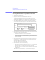
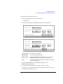
To Check the 4155B/4156B Operation
1. Make sure that the line switches are set to off.
2. If the 41501A/B will be used with the 4155B/4156B, connect the 41501A/B as
shown in “Connecting the 41501A/B SMU/Pulse Generator Expander” on page
2-11.
3. On the 4155B/4156B, make sure that the Circuit Common terminal is connected
to the frame ground terminal by a shorting-bar.
WARNING
If the Circuit Common terminal is not connected to the frame ground terminal,
a potential shock hazard exists.
4. Connect the power cable from the 4155B/4156B to an ac power outlet. If the
41501A/B will be used, connect the power cable from the 41501A/B to the
outlet.
5. If the 41501A/B is installed, press the LINE button to turn the instrument on.
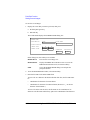
6. Press the LINE button to turn the 4155B/4156B on. The initialization screen will
appear on the display of the instrument.
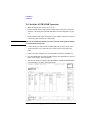
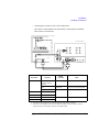
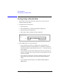
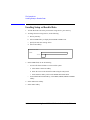
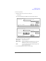
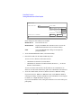
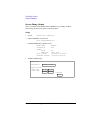
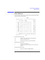
7. After the initialization is finished, the CHANNELS: CHANNEL DEFINITION
screen will appear as shown in the figure below.
2-8
Agilent 4155B/4156B User’s Guide Vol.1, Edition 4
Installation
Inspection
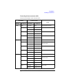
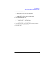
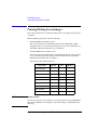
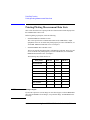
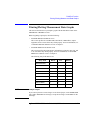
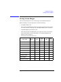
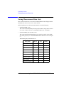
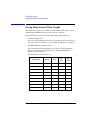
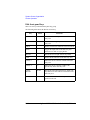
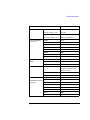
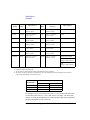
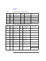
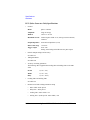
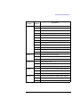
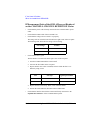
8. Make sure that the units displayed in the UNIT column match the units installed.
The following table shows the displayed units in the UNIT column:
4155B
4156B
SMU1:MP
SMU2:MP
SMU3:MP
SMU4:MP
VSU1
VSU2
VMU1
VMU2
SMU1:HR
SMU2:HR
SMU3:HR
SMU4:HR
VSU1
VSU2
VMU1
VMU2
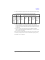
Additional Units by Using 41501A/B Expander
(Opt. 402)
PGU1
PGU2
GNDU
(Opt. 410)
SMU5:HP
GNDU
(Opt. 412)
SMU5:HP
PGU1
PGU2
GNDU
(Opt. 420)
SMU5:MP
SMU6:MP
GNDU
(Opt. 422)
SMU5:MP
SMU6:MP
PGU1
PGU2
GNDU
9. If the 41501A/B units are not displayed in the UNIT column, turn off the
4155B/4156B and the 41501A/B. Make sure that the 41501A/B interface board
is firmly inserted into the 4155B/4156B. Turn on the 41501A/B, then turn on the
4155B/4156B.
10. Press the System key on the front panel, then select MISCELLANEOUS
softkey. Confirm that the POWER LINE FREQUENCY is correct for your site.
If not, select the correct softkey.
When you turn on the 4155B/4156B, the unit will execute a power-on self-test. If no
error message is displayed on the screen, the 4155B/4156B is operating correctly.
If a problem occurs, see Chapter 10.
Agilent 4155B/4156B User’s Guide Vol.1, Edition 4
2-9
Installation
Inspection
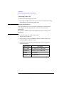
To Execute Diagnostics and Calibration
You can execute diagnostics and/or calibration to verify the operation of the
4155B/4156B.
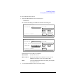
1. Press System key, then CALIB/DIAG softkey.
The SYSTEM: SELF-CALIBRATION/DIAGNOSTICS screen is displayed.
2. Disconnect all cables from the measurement terminals on the 4155B/4156B rear
panel.
3. If you want to execute both diagnostics and calibration, select DIAG SELFTST
ALL softkey.
4. If you want to execute calibration only, select CALIB ALL softkey.
5. To stop the diagnostics or calibration, select STOP softkey.
2-10
Agilent 4155B/4156B User’s Guide Vol.1, Edition 4
Installation
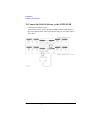
Connecting the 41501A/B SMU/Pulse Generator Expander
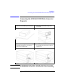
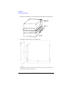
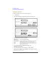
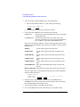
Connecting the 41501A/B SMU/Pulse Generator
Expander
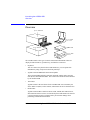
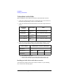
WARNING
1. Place the 41501A/B on your workbench.
2. Place the 4155B/4156B on top of the
41501A/B.
3. Remove the blank panel labeled "To
Expander Box Interface" from the rear
panel of the 4155B/4156B.
4. Insert the 41501A/B interface board into
the 4155B/4156B, then attach it with the
thumbscrews.
The 4155B/4156B, together with the 41501A/B, weights about 37 kg (81.8 lb).
The 4155B/4156B is not anchored to the 41501A/B. Use caution when handling.
Agilent 4155B/4156B User’s Guide Vol.1, Edition 4
2-11
Installation
Installing Accessories
Installing Accessories
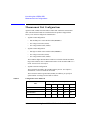
This section describes how to install the 4155B/4156B and accessories. Additional
information regarding airflow can be found in the “Ventilation Requirements” on
page 2-5.
This section describes how to:
•
install the 16442A test fixture
•
install the 16441A R-box
•
install the 16440A SMU/pulse generator selector
•
connect the 16440A to the 4155B/4156B
•
connect a measurement cable to a connector plate
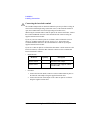
When you install a keyboard, connect the keyboard to the keyboard interface on the
front-panel before switching on the 4155B/4156B. The 4155B/4156B recognizes
the keyboard during the power-on self-test.
2-12
Agilent 4155B/4156B User’s Guide Vol.1, Edition 4
Installation
Installing Accessories
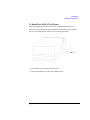
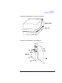
To Install the 16442A Test Fixture
Before performing this procedure, turn off the 4155B/4156B and 41501A/B.
When you use the 16442A test fixture without the 16441A R-box or the 16440A
selector, you can stabilize the 16442A as shown in the figure below.
1. Put a stabilizer on both sides of the test fixture.
2. Attach each stabilizer to the unit with a flathead screw.
Agilent 4155B/4156B User’s Guide Vol.1, Edition 4
2-13
Installation
Installing Accessories
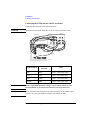
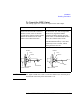
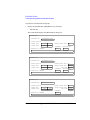
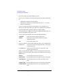
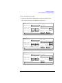
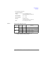
Connecting the 4155B and the 16442A test fixture
Connect the 4155B and the 16442A as shown below.
CAUTION
To prevent electrical shock during use, be sure to connect the interlock cable.
16442A
4. MPSMUs
2. VSUs
3. VMUs
1. Intlk
4155B
4155B Terminals
16442A
Terminals
Cable
Intlk
Intlk
3 m or 1.5 m Interlock Cable
VSU
VSU
3 m or 1.5 m Coaxial Cable
VMU
VMU
3 m or 1.5 m Coaxial Cable
MPSMU
SMU
3 m or 1.5 m Triaxial Cable
WARNING
There are potentially hazardous voltages of up to ±100 V at the Force and
Guard terminals. To prevent electrical shock, do not expose these lines.
CAUTION
Never connect the Guard terminal to any output, including circuit common, frame
ground, or any other guard terminal. Doing so will damage the SMU.
2-14
Agilent 4155B/4156B User’s Guide Vol.1, Edition 4
Installation
Installing Accessories
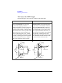
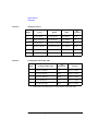
Connecting the 4156B and the 16442A test fixture
Connect the 4156B and the 16442A as shown below.
CAUTION
To prevent electrical shock during use, be sure to connect the interlock cable.
16442A
4. HRSMUs
3. VMUs
2. VSUs
1. Intlk
4156B
4156B Terminals
16442A
Terminals
Cable
Intlk
Intlk
3 m or 1.5 m Interlock Cable
VSU
VSU
3 m or 1.5 m Coaxial Cable
VMU
VMU
3 m or 1.5 m Coaxial Cable
HRSMU
SMU1 and SMU2
3 m or 1.5 m Kelvin Triaxial Cable
SMU3 and SMU4
SMU5 and SMU6
WARNING
There are potentially hazardous voltages of up to ±100 V at the Force, Sense,
and Guard terminals. To prevent electrical shock, do not expose these lines.
CAUTION
Never connect the Guard terminal to any output, including circuit common, chassis
ground, or any other guard terminal. Doing so will damage the SMU.
Agilent 4155B/4156B User’s Guide Vol.1, Edition 4
2-15
Installation
Installing Accessories
Connect the 41501A/B measurement terminals to the 16442A input as follows:
41501A/B
Terminals
16442A
Terminals
Cable
GNDU
GNDU
3 m or 1.5 m GNDU Cable
PGU
PGU
3 m or 1.5 m Coaxial Cable
MPSMU
SMU
3 m or 1.5 m Triaxial Cable
HPSMU
SMU1 and SMU2
3 m or 1.5 m Kelvin Triaxial Cable
SMU3 and SMU4
SMU5 and SMU6
WARNING
Use Agilent 16493H GNDU cable to connect the GNDU to a test fixture or a
connector plate. Do not use the triaxial cable. The GNDU cable is rated for up
to 1.6 A, but the maximum current rating of the triaxial cable is 1 A.
WARNING
There are potentially hazardous voltages of up to ±200 V at the Force, Sense,
and Guard terminals. To prevent electrical shock, do not expose these lines.
CAUTION
Never connect the Guard terminal to any output, including circuit common, chassis
ground, or any other guard terminal. Doing so will damage the SMU.
2-16
Agilent 4155B/4156B User’s Guide Vol.1, Edition 4
Installation
Installing Accessories
Installing the 16442A test fixture with other accessories
The 16442A test fixture can be installed with an 16441A R-box, 16440A selector, or
both. The following figure shows how to attach the 16442A to other accessories.
Agilent 4155B/4156B User’s Guide Vol.1, Edition 4
2-17
Installation
Installing Accessories
To Install the 16441A R-Box
Before installing the 16441A R-box, turn off the 4155B/4156B and 41501A/B.
1. Connect the To R-Box terminal on the 4155B/4156B to the Control terminal on
the 16441A rear panel using a 3.0 m or 1.5 m control cable.
2. Connect the instrument measurement terminals to the 16441A input terminals as
follows:
Instrument
terminals
16441A Input
Cable
4155B MPSMU
Input Force
3 m or 1.5 m Triaxial Cable
4156B HRSMU
Input
(Force/Sense)
3 m or 1.5 m Kelvin Triaxial Cable
41501A/B MPSMU
Input Force
3 m or 1.5 m Triaxial Cable
41501A/B HPSMU
Input
(Force/Sense)
3 m or 1.5 m Kelvin Triaxial Cable
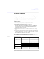
3. Connect the 16441A output terminals to the 16442A input terminals, or to the
connector plate input terminals, using 40 cm triaxial cables as shown below:
16441A Output
16442A Input or Connector Plate Input
Output Force a
SMU1, 2, 3, 4, 5, or 6
Output Force b
SMU1
SMU3
SMU5
Output Sense b
SMU2
SMU4
SMU6
a. For non-Kelvin connection.
b. For the Kelvin connection, two triaxial cables must be used to connect the 16441A and the 16442A, instead of a Kelvin triaxial cable.
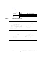
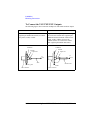
Installing the 16441A R-box with other accessories
You can attach the 16441A R-box to the 16442A test fixture or to your shielding
box, as shown in the following figures.
2-18
Agilent 4155B/4156B User’s Guide Vol.1, Edition 4
Installation
Installing Accessories
Attaching the 16441A R-Box to the 16442A Test Fixture
Attaching the 16441A R-Box to the Shielding Box
Agilent 4155B/4156B User’s Guide Vol.1, Edition 4
2-19
Installation
Installing Accessories
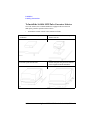
To Install the 16440A SMU/Pulse Generator Selector
To use the 16440A, the 4155B/4156B must be equipped with an 41501A/B
SMU/pulse generator expander with two PGUs.
•
To attach the 16440A selector to the 16442A test fixture:
1. Place the 16440A selector on your
workbench.
2. Place the 16442A test fixture on top of the
16440A selector.
3. Position a plate on both sides.
4. Attach each plate using the three flathead
screws supplied with the instrument.
2-20
Agilent 4155B/4156B User’s Guide Vol.1, Edition 4
Installation
Installing Accessories
•
The following steps apply when using two 16440A SMU/pulse generator
selectors:
5. Place the second 16440A on your
workbench. Place the 16440A selector and
the 16442A test fixture on top of the
second 16440A.
6. Position a plate on both sides.
7. Attach each plate using the three flathead
screws supplied with the instrument.
Agilent 4155B/4156B User’s Guide Vol.1, Edition 4
2-21
Installation
Installing Accessories
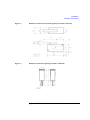
•
To attach an 16441A R-box to the 16442A test fixture and the 16440A selector:
•
To attach the 16440A selector to a shielding box:
The figure above shows the spacing of the 16440A screw holes. You need to prepare four
screws and nuts to match the screw holes.
2-22
Agilent 4155B/4156B User’s Guide Vol.1, Edition 4
Installation
Installing Accessories
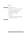
•
If you use two 16440As, connect the 16440As before connecting to the shielding
box, as shown below:
1. Place the 16440A on your workbench.
2. Place the second 16440A on top of the
16440A.
3. Position a plate on both sides.
4. Attach each plate using the three flathead
screws supplied with the instrument.
Agilent 4155B/4156B User’s Guide Vol.1, Edition 4
2-23
Installation
Installing Accessories
•
To connect the selector to the shielding box:
1. Attach an angle bracket to each side of the 16440A, using the screws supplied.
2. Place the 16440A(s) on the side panel of
the shielding box.
3. Position four nuts on the inside panel of
the shielding box.
4. Attach the angle bracket to the shielding
box using four flathead screws.
2-24
Agilent 4155B/4156B User’s Guide Vol.1, Edition 4
Installation
Installing Accessories
•
To attach an 16441A R-box to the 16440A selector on the shielding box:
Agilent 4155B/4156B User’s Guide Vol.1, Edition 4
2-25
Installation
Installing Accessories
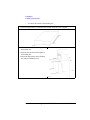
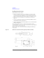
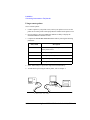
To Connect the 16440A Selector to the 4155B/4156B
•
Connecting two 16440A selectors
If you use two 16440A, connect the Control Output terminal of the selector to
the Control Input terminal of the second selector using a 40 cm control cable as
shown below.
2-26
Agilent 4155B/4156B User’s Guide Vol.1, Edition 4
Installation
Installing Accessories
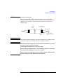
•
Connecting the 16440A selector to the 4155B/4156B
Turn off the 4155B/4156B and 41501A/B before connecting the instruments.
Then connect as shown below.
4155/4156
16442A Test Fixture
4
2
41501
16440A Selector
3
1
16440A
Terminal
Cable
To SMU/Pulse
Generator Selector
Interface
CONTROL Input
3.0 m or 1.5 m Control Cable
PGU
Input PGU a
3.0 m or 1.5 m Coaxial Cable
MPSMU or HPSMU
Input SMU
3.0 m or 1.5 m Triaxial Cable
Output Selected b
40 cm Triaxial Cable
Instrument
41501A/B
Terminal
4155B
MPSMU
4156B
HRSMU
16442A
SMU
Connector Plate
SMU
a. You can use two inputs for one selector, and four inputs for two selectors.
b. You can use two outputs for one selector and four outputs for two selectors. Selector
output is either one of the PGU outputs or the SMU output.
Agilent 4155B/4156B User’s Guide Vol.1, Edition 4
2-27
Installation
Installing Accessories
To Connect the Measurement Cable to the Connector
Plate
This section provides instructions for connecting the measurement cables from the
4155B/4156B to the connector plate. For connector plate installation information,
refer to the 16495 Installation Guide.
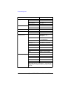
The following connector plates are available for the 4155B/4156B:
Agilent 16495H
Connector Plate with 6 Triaxial Connectors
Option 001 has 6 triaxial through connectors (female to
female), 6 BNC through connectors (female to female), an Intlk
connector, and a GNDU connector (triaxial through, female to
female). The back of the Intlk connector is designed for
soldering.
Option 002 has 6 triaxial connectors, 6 BNC connectors, an
Intlk connector, and a GNDU connector. The back of each
connector is designed for soldering.
Agilent 16495J
Connector Plate with 8 Triaxial Connectors
Option 001 has 8 triaxial through connectors (female to
female), 4 BNC through connectors (female to female), an Intlk
connector, and a GNDU connector (triaxial through, female to
female). The back of the Intlk connector is designed for
soldering.
Option 002 has 8 triaxial connectors, 4 BNC connectors, an
Intlk connector, and a GNDU connector. The back of each
connector is designed for soldering.
2-28
Agilent 4155B/4156B User’s Guide Vol.1, Edition 4
Installation
Installing Accessories
Connecting the measurement cables
Connect the measurement cables as shown below.
Instrument
Connector Plate
Cable
Model No.
4155B
Connector
16495H/J
Intlk
16493J Interlock Cable
MPSMU
16495H
INPUT 1 to 6
Triaxial Cable
16495J
INPUT 1 to 8
16495H
INPUT 7 to 12
16495J
INPUT 9 to 12
16495H
INPUT 7 to 12
16495J
INPUT 9 to 12
Intlk
16495H/J
Intlk
16493J Interlock Cable
HRSMU
16495H
INPUT 1 to 6
16495J
INPUT 1 to 8
Triaxial Cable or Kelvin
Triaxial Cable
16495H
INPUT 7 to 12
16495J
INPUT 9 to 12
16495H
INPUT 7 to 12
16495J
INPUT 9 to 12
GNDU
16495H/J
GNDU
16493H GNDU Cable
HPSMU
16495H
INPUT 1 to 6
16495J
INPUT 1 to 8
Triaxial Cable or Kelvin
Triaxial Cable
16495H
INPUT 1 to 6
16495J
INPUT 1 to 8
16495H
INPUT 7 to 12
16495J
INPUT 9 to 12
VMU
VSU
VMU
41501A/B
Connector
Intlk
VSU
4156B
Model No.
MPSMU
PGU
BNC cable
BNC cable
BNC cable
BNC cable
Triaxial Cable
BNC cable
Agilent 4155B/4156B User’s Guide Vol.1, Edition 4
2-29
Installation
Installing Accessories
Connecting the interlock terminal
The 4155B/4156B provides an interlock terminal to prevent you from receiving an
electrical shock from high voltage (more than ±40 V). If the interlock terminal is
open, the 4155B/4156B cannot force high voltage more than ±40 V.
When using the 16495H/16495J connector plate or the 16442A test fixture, connect
the 4155B/4156B Intlk connector to the external interlock connector using the
supplied 16493J interlock cable.
If you use your own connector plate or test fixture, make an interlock circuit as
shown in “To Make an Interlock Circuit” on page 2-33. Then connect the
4155B/4156B Intlk connector to the external interlock connector by using the
supplied 16493J interlock cable.
If you use a connector plate or test fixture that has a BNC coaxial connector as the
interlock connector, connect the BNC interlock connector to the 4155B/4156B
interlock terminal as follows:
•
Required Parts:
Model No.
•
Quantity
Description
Agilent 16435A
1
Interlock Cable Adapter
Agilent 16493J
1
Interlock Cable (supplied with the
4155B/4156B)
Procedure:
1. Connect the interlock (Intlk) connector on the 4155B/4156B rear panel to
the interlock cable adapter using the supplied interlock cable.
2. Connect the interlock cable adapter to the connector plate or test fixture
using the supplied coaxial cable.
2-30
Agilent 4155B/4156B User’s Guide Vol.1, Edition 4
Installation
Mounting Connectors
Mounting Connectors
Previous sections described how to install the available accessories, and the 16495
Installation Guide provides the information on how to install connector plates on the
shielding box. However, you may choose to mount connectors directly on your own
connector plate or test fixture.
To do this, you will need to make connector holes and mount the connectors
yourself. This section contains information on connector hole dimensions.
To mount connectors:
1. Select the appropriate parts for your application. See Table 2-1.
2. Make the holes and mount the connectors. See Table 2-2.
For Kelvin connections using the 4156B SMU, use Agilent 16494B Kelvin
cable. A Kelvin cable requires a Kelvin triaxial connector, which has two
connector holes and three screw holes.
3. Build the interlock circuit shown in “To Make an Interlock Circuit” on page
2-33.
4. Attach cables from the connectors to the DUT (device under test). Refer to “To
Connect the GNDU Output”, “To Connect the SMU Output”, and “To Connect
the VSU/VMU/PGU Outputs” later in this chapter.
Table 2-1 lists the parts required to mount connectors on your shielding box. The
type and quantity of parts needed will depend on your application.
Table 2-1
Recommended Parts
Usage
Making an interlock
circuit
Agilent Part No.
Description
1252-1419
Interlock Connector (6 pin,
female)
3101-0302 or 3101-3241
Switch
1450-0641
LED (VF @ 2.1 V @ IF = 10 mA)
8150-4690
Wire
Connecting GNDU to
DUT
1250-2457
Triaxial Connector (female)
8120-3674 or 8150-2639
Coaxial Cable or Wire
Connecting SMU to
DUT
1250-2457
Triaxial Connector (female)
8120-4461
Low Noise Coaxial Cable
Agilent 4155B/4156B User’s Guide Vol.1, Edition 4
2-31
Installation
Mounting Connectors
Usage
Table 2-2
Agilent Part No.
Description
Connecting
VSU/VMU to DUT
1250-0118
BNC Connector (female)
8150-0447
Wire
Connecting PGU to
DUT
1250-0118
BNC Connector (female)
8120-0102 or 8120-4461
Low Noise Coaxial Cable
Dimensions of Connector Holes
Kelvin Triaxial Connector (in mm)
Triaxial Connector (in mm)
BNC Connector (in mm)
Interlock Connector (in mm)
2-32
Agilent 4155B/4156B User’s Guide Vol.1, Edition 4
Installation
Mounting Connectors
To Make an Interlock Circuit
The interlock circuit is designed to prevent electrical shock when a user touches the
measurement terminals.
CAUTION
You must install an interlock circuit on a shielding box to prevent hazardous
voltages when the door of the shielding box is open.
Figure 2-1 shows the pin assignments of the interlock connector mounted on a
connector plate or test fixture.
Figure 2-1
Interlock Connector Pin Assignments
WARNING
Potentially hazardous voltages may be present at the Force, Guard, and Sense
terminals when the interlock terminals are shorted.
Agilent 4155B/4156B User’s Guide Vol.1, Edition 4
2-33
Installation
Mounting Connectors
Installing the interlock circuit
Install the interlock circuit as follows:
1. Mount two mechanical switches on your shielding box, so that the switches
close when the door of the shielding box is closed, and open when the door is
opened. For the dimensions of the switch, see Figure 2-2 and Figure 2-3 below.
2. Mount an LED on your shielding box. For the dimensions of the LED, see
Figure 2-4.
3. Use wire to connect the two switches in series between pin number 1 and 2 (or
3) of the interlock connector. See Figure 2-1.
4. Use wire to connect the LED between pin number 4 and 5 (or 6) of the interlock
connector. See Figure 2-1.
If the 4155B/4156B Intlk connector is connected to the interlock circuit, the
4155B/4156B SMU cannot force more than ±40 V when the door is open. When the
door is closed, it can force more than ±40 V.
When more than ±40 V is forced from an SMU, the LED lights to indicate high
voltage output.
Figure 2-2
Dimensions of the Interlock Switch (Agilent part number 3101-0302)
2-34
Agilent 4155B/4156B User’s Guide Vol.1, Edition 4
Installation
Mounting Connectors
Figure 2-3
Dimensions of the Interlock Switch (Agilent part number 3101-3241)
Figure 2-4
Dimensions of the LED (Agilent part number 1450-0641)
Agilent 4155B/4156B User’s Guide Vol.1, Edition 4
2-35
Installation
Mounting Connectors
NOTE
To Perform an Interlock Circuit Test
To confirm that the interlock circuit is operating properly, perform the following
test.
1. Connect the Intlk terminal of the 4155B/4156B to your interlock circuit.
2. Press System key, then select CALIB/DIAG softkey to display the
SYSTEM: SELF-CALIBRATION/DIAGNOSTICS screen.
3. In the CALIB/DIAG field, select DIAG softkey.
4. In the CATEGORY field, select I/O PERIPH softkey.
5. Move the pointer to 403 (INT.) Interlock LED.
6. Select EXECUTE softkey.
7. Confirm the following:
•
the LED turns on within 1 second when the interlock circuit is shorted.
•
the LED turns off within 1 second when the interlock circuit is opened.
8. To stop the interlock test, select STOP softkey.
2-36
Agilent 4155B/4156B User’s Guide Vol.1, Edition 4
Installation
Mounting Connectors
To Connect the GNDU Output
The following figures show connection examples for the GNDU output.
Kelvin connections
non-Kelvin connections
Use a low-noise coaxial cable (Agilent part
number 8120-3674) from the connector to
the prober, socket, or DUT as shown. To
cancel the effects of cable resistance, connect
the Sense line and Force line as close as
possible to the terminal of the DUT.
Short the Sense and Force on the connector
as shown below. Use AWG 22 single-strand
insulated wire (Agilent part number
8150-2639) from the connector plate to the
prober, socket, or DUT. Measurement results
include the residual resistance of the
connection wire. For a quick connection
where measurement accuracy is not critical,
connect only Force to the DUT, without
shorting the Sense and Force.
Insulator
Insulator
FORCE
FORCE
SENCE
SENCE
To
DUT
Plate
Triaxial Connector
CAUTION
To
DUT
Wire
Coaxial Cable
Plate
Triaxial Connector
Use Agilent 16493H GNDU cable to connect the GNDU to your connector plate or
test fixture. Do not use the triaxial cable. The GNDU is rated for up to 1.6 A, while
the maximum current rating of the triaxial cable is 1 A.
Agilent 4155B/4156B User’s Guide Vol.1, Edition 4
2-37
Installation
Mounting Connectors
To Connect the SMU Output
The following figures show connection examples for the SMU output.
Kelvin connections
non-Kelvin connections
This connection is for the 4156B HRSMU or
the 41501A/B HPSMU. Use low-noise
coaxial cable (Agilent part number
8120-4461) from the connector to the prober,
socket, or DUT as shown. To cancel the
effects of cable resistance, connect the Sense
line and Force line as close as possible to the
DUT terminal. To prevent oscillations, do
not use cables longer than 1.5 m. To make
accurate measurements when applying high
currents, extend the guard as far as possible
from the front panel connector to the DUT.
Physically stabilize the cables with tape.
The following figure is for the
HRSMU/HPSMU connection using Kelvin
triaxial cable. For the MPSMU connection,
and for the HRSMU/HPSMU connection
using triaxial cable, connect the cable to the
Force terminal only. Use low-noise coaxial
cable (Agilent part number 8120-4461). To
make accurate measurements when applying
high currents, extend the guard as far as
possible from the front panel connector to the
DUT. Measurement results include residual
resistance from the connection cable.
Insulator
GUARD
Insulator
GUARD
FORCE
FORCE
To
DUT
Triaxial
Connector
Coaxial Cable
To
DUT
Triaxial
Connector
SENCE
SENCE
GUARD
Insulator
Plate
2-38
Coaxial Cable
Plate
GUARD
Insulator
Agilent 4155B/4156B User’s Guide Vol.1, Edition 4
Installation
Mounting Connectors
NOTE
Low-Noise Coaxial Cable
When you make an SMU output connection by using low-noise coaxial cable
(Agilent part number 8120-4461), trim the conductive layer and the insulator(clear)
so that the center conductor is insulated from the conductive layer. Refer to the
following figure.
Insulator
(black)
Outer Conductor
for GUARD signal
Insulator (clear)
Conductive Layer
(black)
Center Conductor
for FORCE or SENSE
signal
CAUTION
Never connect the Guard terminal to any output, including circuit common, chassis
ground, or any other guard terminal. Doing so will damage the SMU.
WARNING
Potentially hazardous voltages, up to ±100 V (±200 V for HPSMU), are present
at the Force, Sense, and Guard terminals.
To prevent electrical shock, do not expose these lines.
Before turning the 4155B/4156B on, connect the Intlk terminal to a switch that
turns off when the shielding box access door is opened.
Before you touch any connections to these terminals, turn the 4155B/4156B off,
disconnect the power cable, and discharge any capacitors.
Agilent 4155B/4156B User’s Guide Vol.1, Edition 4
2-39
Installation
Mounting Connectors
To Connect the VSU/VMU/PGU Outputs
The following figures show connection examples for VSU/VMU and PGU output.
VSU/VMU connector
PGU connector
Use AWG 24 single-strand insulated wire
(Agilent part number 8150-0447) to connect
to a prober, socket, or DUT.
Regardless of the output impedance setting,
use a low-noise coaxial cable (Agilent part
number 8120-0102) from the connector to a
prober, socket, or DUT. If you use an
16440A selector, use a low-noise coaxial
cable (Agilent part number 8120-4461).
COMMON
COMMON
Insulator
Insulator
Signal Line
Signal Line
To
DUT
To
DUT
Wire
Coaxial Cable
Plate
BNC Connector
2-40
Plate
BNC Connector
Agilent 4155B/4156B User’s Guide Vol.1, Edition 4
Installation
Connecting Instruments or Peripherals
Connecting Instruments or Peripherals
The 4155B/4156B provides an GPIB interface, parallel I/O interface, and LAN
interface for connection with other instruments or peripherals. This section contains
information required to connect instruments or peripherals.
To Connect GPIB Instruments or Peripherals
The 4155B/4156B has an GPIB interface for instrument, printer, or plotter control.
•
If you use an external controller with the 4155B/4156B, connect an GPIB cable
between the controller and the 4155B/4156B.
•
If you control instruments using the 4155B/4156B built-in IBASIC capability,
connect an GPIB cable between the instrument and the 4155B/4156B.
•
If you use an GPIB printer or plotter to make hard copies, connect an GPIB
cable between the printer or plotter and the 4155B/4156B.
To use the GPIB interface, you will need to fill in the following entry fields on the
SYSTEM: MISCELLANEOUS screen. For details of this setup screen, see
“SYSTEM: MISCELLANEOUS screen” in Chapter 5.
Entry Field Name
4155B is
(4156B is)
Description
Selects SYSTEM CONTROLLER or NOT SYSTEM
CONTROLLER.
Select NOT SYSTEM CONTROLLER if the 4155B/4156B will
be used with an external controller.
Select SYSTEM CONTROLLER if the 4155B/4156B will be
used to control other instruments or peripherals.
GPIB
ADDRESS
Sets the GPIB addresses of the 4155B/4156B and peripheral
(printer or plotter).
Enter the GPIB address in the 4155B or the 4156B field.
Enter the GPIB address of the printer or plotter in the HARD
COPY field.
Agilent 4155B/4156B User’s Guide Vol.1, Edition 4
2-41
Installation
Connecting Instruments or Peripherals
REMOTE
CONTROL
Selects the 4155B/4156B Control Command Set used to control
the unit with an external controller or built-in IBASIC.
Select "4155/4156" to use the 4155B/4156B command set (SCPI
or FLEX commands).
Select "4145" to use the 4145 syntax command set. You will also
need to set the DELIMITER and EOI fields.
To Connect Parallel Peripherals
The 4155B/4156B has a 25 pin parallel I/O interface port for connecting peripherals,
such as a Centronics parallel printer.
To use a parallel printer, connect a parallel cable from the 4155B/4156B to the
peripheral. You do not need to define any fields on the setup screen.
To make hard copies, refer to Chapter 4.
2-42
Agilent 4155B/4156B User’s Guide Vol.1, Edition 4
Installation
Connecting Instruments or Peripherals
To Connect to a LAN
The 4155B/4156B has a LAN connector (Ethernet IEEE 802.3 10BASE-T, RJ45
connector) on the rear panel, and can be connected to your LAN which satisfies the
specifications for Ethernet IEEE 802.3 10BASE-T for a 10M bps CSMA/CD local
area network.
Connecting the 4155B/4156B to your LAN allows you to do the following:
•
Use the 4155B/4156B as a NFS client.
The 4155B/4156B can mount a directory on your NFS server. You can then store
and retrieve 4155B/4156B data files using this directory.
•
Use a remote printer.
The 4155B/4156B can output to a remote printer via your printer server. You can
print the 4155B/4156B setup screen, measurement results, and screen images on
the printer.
NOTE
Executing LAN Interface Test
If you want to check the LAN interface installed in the 4155B/4156B, do following:
1. Turn the 4155B/4156B on.
2. Attach the LAN I/F test adapter (Agilent part number 04155-61631, furnished
with the 4155B/4156B) to the LAN connector on the rear panel.
3. Press System key, then select CALIB/DIAG softkey to display the
SYSTEM: SELF-CALIBRATION/DIAGNOSTICS screen.
4. In the CALIB/DIAG field, select DIAG softkey.
5. In the CATEGORY field, select CPU softkey.
6. Move the pointer to 312 (INT.) LAN Interface using the down-arrow key.
7. Select EXECUTE softkey to execute the LAN interface test.
If the 4155B/4156B fails the test, contact to the nearest Agilent Technologies
service office.
Agilent 4155B/4156B User’s Guide Vol.1, Edition 4
2-43
Installation
Connecting Instruments or Peripherals
Connecting to the LAN
To connect the 4155B/4156B to your LAN:
1. Register the 4155B/4156B on your local area network. Include the host name
and IP address assigned for the 4155B/4156B.
NOTE
Network Setup Parameters
If you are uncertain as to your local network configuration, or have questions
concerning the network setup parameters, contact your network system
administrator.
The parameters should be registered and administered by the network system
administrator.
2. Connect the LAN cable to the 4155B/4156B.
3. Turn the 4155B/4156B on.
4. Press System key, then select MISCELLANEOUS softkey to display the
SYSTEM: MISCELLANEOUS screen.
5. Complete the 4155B (4156B) NETWORK SETUP table by entering the
following parameters:
Entry Field
2-44
Description
HOST NAME
Host name of the 4155B/4156B
IP ADDRESS
IP address of the 4155B/4156B
USER ID
Your user ID
GROUP ID
Your group ID
Agilent 4155B/4156B User’s Guide Vol.1, Edition 4
Installation
Connecting Instruments or Peripherals
Using the 4155B/4156B as an NFS client
To use the 4155B/4156B as an NFS client:
1. Enable NFS service on your NFS server.
2. Export a directory on the NFS server to be mounted by the 4155B/4156B.
3. Press System key, then select MISCELLANEOUS softkey to display the
SYSTEM: MISCELLANEOUS screen.
4. Complete the NETWORK DRIVE SETUP table by entering the following
parameters:
Entry Field
Description
LABEL
Label or name for the setup information on the
NETWORK DRIVE SETUP table.
IP ADDRESS
IP address of NFS server.
DIRECTORY
Name of the directory to be mounted by the
4155B/4156B.
5. Select ADD softkey to register the setup in the internal memory.
6. To mount the directory and to perform file operations, refer to Chapter 3.
Agilent 4155B/4156B User’s Guide Vol.1, Edition 4
2-45
Installation
Connecting Instruments or Peripherals
Using a remote printer
To use a remote printer:
1. Connect a printer to your printer server, and set your printer server to use the
printer as an remote printer. Then lpd/lpr must be enabled on the printer server.
2. Press System key, then select MISCELLANEOUS softkey to display the
SYSTEM: MISCELLANEOUS screen.
3. Complete the NETWORK PRINTER SETUP table by entering the following
parameters:
Entry Field
Description
PRINTER
Printer name assigned to the printer, and defined
on the printer server.
IP ADDRESS
IP address of the printer server.
TEXT OUT
Text output option of lpr command.
GRAPH OUT
Graphics output option of lpr command.
SERVER TYPE
Server type (BSD or SystemV).
4. Select ADD softkey to register the setup in the internal memory.
5. To make hard copies using the remote printer, refer to Chapter 4.
4155B/4156B
lpr
Printer Server
lpd
Printer
LAN
2-46
Agilent 4155B/4156B User’s Guide Vol.1, Edition 4
3
File Operations
Agilent 4155B/4156B User’s Guide Vol.1, Edition 4
File Operations
This chapter covers the following file operations:
•
selecting a mass storage device
•
listing a file catalog
•
storing setup or results data
•
storing data in spreadsheet format
•
loading setup or results data
•
changing a file name
•
removing a file/directory
•
copying a file
•
creating a directory on a network file system
•
changing the working directory
•
initializing a diskette
•
backing up a diskette
You can use these file operations on the internal memory, a diskette in the built-in
flexible disk drive, or on a network file system that Agilent 4155B/4156B mounts.
You can perform file operations by:
•
selecting softkeys on the SYSTEM: FILER screen. (All file operations can be
performed this way.)
•
selecting the front-panel keys Get and Save from the User File key group. (Only
store and load file operations can be performed this way.)
For details on the SYSTEM: FILER screen, refer to the “SYSTEM: FILER screen”
in Chapter 5.
3-2
Agilent 4155B/4156B User’s Guide Vol.1, Edition 4
File Operations
NOTE
To Use the Network File System
The 4155B/4156B can be an NFS client, and can use the network file system as a
mass storage device.
To use the network file system:
1. Connect the 4155B/4156B to your LAN. See “To Connect to a LAN” in Chapter
2.
2. Complete the NETWORK SETUP table on the SYSTEM: MISCELLANEOUS
screen.
3. Complete the NETWORK DRIVE SETUP table on the SYSTEM:
MISCELLANEOUS screen.
For information on the SYSTEM: MISCELLANEOUS screen, see
“SYSTEM: MISCELLANEOUS screen” in Chapter 5.
NOTE
Situations When You Cannot Store/Load Files
The Save and Get keys are available from any screen. However, the Save and Get
functions will not work under the following conditions:
•
during measurement or forcing stress
•
when an error message is displayed
•
when the HELP screen is displayed
•
when the KNOB SWEEP screen is displayed
•
when the SCREEN DUMP, PRINT/PLOT, or GRAPH PLOT dialog is displayed
Agilent 4155B/4156B User’s Guide Vol.1, Edition 4
3-3
File Operations
Selecting a Mass Storage Device
Selecting a Mass Storage Device
To start a file operation, you must specify the mass storage device by selecting either
the built-in flexible disk drive or a network file system.
1. Press System key.
2. Select FILER softkey to display the SYSTEM: FILER screen.
3. Move the cursor to the DISK entry field.
4. Select one of the following secondary softkeys.
FLOPPY
Specifies the diskette in the built-in flexible disk drive.
Insert a diskette into the built-in flexible disk drive.
drive name
If you have set up a drive label in the NETWORK DRIVE
SETUP table, this label will appear as a softkey. Up to four
softkeys can be added this way.
Before selecting one of these directories, it must be exported so
that it can be mounted by the 4155B/4156B.
When this softkey is pressed, the 4155B/4156B mounts the
directory on an NFS server, and displays the file catalog in the
FILE CATALOG area. The directory name will be shown next
to the DISK entry field, and it will be the root directory.
To unmount the directory, choose another secondary softkey or
turn off the 4155B/4156B.
3-4
Agilent 4155B/4156B User’s Guide Vol.1, Edition 4
File Operations
Listing a File Catalog
Listing a File Catalog
1. Press System key.
2. Select FILER softkey to display the SYSTEM: FILER screen.
3. Specify the mass storage device.
4. Select FILE CATALOG softkey. A maximum of 199 file names can be
displayed in the FILE CATALOG area.
5. Use the rotary knob to move the cursor or to scroll through the list of file names.
For details on the FILE CATALOG area, refer to “SYSTEM: FILER screen” in
Chapter 5.
To Display File Comments (only for diskette)
If the built-in flexible disk drive is specified as the mass storage device, the FILE
CATALOG area will not include the file comments. To display the file comments,
select one of the following softkeys:
READ
COMMENT
Reads and displays the comments for the selected file.
READ
COMMENT ALL Reads and displays the comments for all files.
To Exit the File Catalog
Select EXIT FILE CATALOG softkey.
To Search for a Desired File Name
Enter an alphanumeric character. The cursor will move to the first file name that
starts with that character.
Agilent 4155B/4156B User’s Guide Vol.1, Edition 4
3-5
File Operations
Storing Setup or Results Data
Storing Setup or Results Data
1. To store data to a file in the current mass storage device, press Save key to
display the SAVE setup fields.
2. To change the mass storage device:
a. Press System key.
b. Select FILER softkey to display the SYSTEM: FILER screen.
c. Specify the new mass storage device.
d. Select SAVE softkey to display the SAVE setup fields.
FUNCTION:SAVE
NAME
TYPE
COMMENT
3. In the NAME field, do one of the following:
•
To store the data in a new file on a diskette, enter a file name that is a
maximum of 8 characters (for DOS format) or a maximum of 6 characters
(for HP LIF format). For HP LIF format, do not use "_" as the last character
of the filename.
•
To store data in a new file on the network file system, enter a file name, 36
characters maximum. The file name and directory path combined can be 58
characters maximum.
•
To store data in an existing file, select FILE CATALOG softkey. Use the
rotary knob to move the cursor to the correct file, then press SELECT
softkey.
•
To store data in an internal memory, select MEM1, MEM2, MEM3 or
MEM4 softkey.
3-6
Agilent 4155B/4156B User’s Guide Vol.1, Edition 4
File Operations
Storing Setup or Results Data
4. In the TYPE field, select:
•
MES softkey for measurement setup data.
•
STR softkey for stress setup data.
•
DAT softkey for measurement setup and results data.
•
CST softkey for customized system data. (This is not available when storing
in internal memory.)
5. In the COMMENT field, you may enter a comment of up to 16 characters.
(When using internal memory, the specified comment will be displayed on the
softkey.)
6. Select EXECUTE softkey. The data will be stored in the specified file.
Any data previously stored in the existing file or internal memory will be
overwritten.
7. Select EXIT softkey.
Agilent 4155B/4156B User’s Guide Vol.1, Edition 4
3-7
File Operations
Storing Results Data in Spreadsheet Format
Storing Results Data in Spreadsheet Format
1. Specify the mass storage device.
2. Display the results data on the GRAPH/LIST: LIST screen.
To display the GRAPH/LIST: LIST screen, press Graph/List key. If the
GRAPH/LIST: GRAPHICS screen is displayed, press Graph/List key again.
3. Select SPREAD SHEET softkey to display the ASCII SAVE setup fields.
For a list of files in the mass storage device, select FILE CATALOG softkey.
FUNCTION:ASCII SAVE
NAME
UNIT
OUTPUT DATA (INDEX NO)
<-->
DELIMITER
STRING MARK
4. In the NAME field, enter the name of the file (with no file extension) in which
you want to save data. The file name may be:
•
a maximum of 8 characters to store on a DOS diskette.
•
To store data in a new file on the network file system, enter a file name, 36
characters maximum. The file name and directory path combined can be 58
characters maximum.
5. In the OUTPUT DATA field, enter the range of results data you want to save
(corresponds to NO. column on the LIST screen). The left field is the lower
limit and the right field is the upper limit.
Select ALL softkey to specify all results data.
6. In the UNIT field, select one for the following:
•
ON softkey will save the unit of measure (such as V or ms) with the results
data. If the UNIT is ON, results data will be treated as string data.
•
OFF softkey will not save the units of measure. Results data will be treated
as numeric data.
With UNIT ON or OFF, invalid data (----) will be treated as string data.
3-8
Agilent 4155B/4156B User’s Guide Vol.1, Edition 4
File Operations
Storing Results Data in Spreadsheet Format
7. In the DELIMITER field, select:
•
SPACE softkey to specify a space as the data delimiter.
•
TAB softkey to specify a tab as the data delimiter.
•
COMMA softkey to specify a comma as the data delimiter.
8. In the STRING MARK field, select:
•
NONE softkey to specify no string marker.
•
“ ” softkey to specify “ ” as the string marker.
•
‘ ’ softkey to specify ‘ ’ as the string marker.
9. Select EXECUTE softkey. The results data will be saved to the specified file,
and a .TXT extension is automatically added.
10. Select EXIT softkey.
Agilent 4155B/4156B User’s Guide Vol.1, Edition 4
3-9
File Operations
Storing Results Data in Spreadsheet Format
Output Format for the ASCII SAVE Function
The following is the output format for each item on the LIST screen. This notation is
used to indicate the string or numeric type:
[S]
string
[S/N]
If the UNIT field is ON, the value is output as a string with a
string marker. If the UNIT field is OFF, the value is output as a
numeric value.
[N]
numeric value
1. user comment
User comment is output as a string with a specified string marker.
•
Example (setups: STRING MARK = “ ”)
“Bipolar Tr. Vce-Ic”
2. VAR1 output range
For sweep measurements:
Format: <VAR1 name> = <start> to <stop> in <step> step
Type:
[S]
[S/N] [S] [S/N] [S] [S/N] [S]
For log sweep measurements, LOG is output for the step value.
•
Example
(setups: UNIT=OFF, STRING MARK= “ ”, DELIMITER=COMMA)
“VCE=”,0.0001,“to”,1,“in”,“LOG”,“step”
For sampling measurements:
Format: @TIME = <start time> to <stop time>
Type:
•
[S]
[S/N]
[S]
[S/N]
Example
(setups: UNIT=ON, STRING MARK = “ ”, DELIMITER=COMMA)
“@TIME=”,“0.00 s”,“to”,“1.516 s”
3-10
Agilent 4155B/4156B User’s Guide Vol.1, Edition 4
File Operations
Storing Results Data in Spreadsheet Format
3. VAR2 output range
Format: <VAR2 name> = <start value>to<stop value>in<step value>step
Type:
•
[S]
[S/N]
[S]
[S/N]
[S]
[S/N]
[S]
Example
(setups: UNIT=OFF, STRING MARK= “ ”, DELIMITER=COMMA)
“IB=”,1E-05,“to”,5E-05,“in”,1E-05,“step”
4. variable names
Format: NO. <variable name> <variable name>
Type:
•
[S]
[S]
[S]
Example (setups: STRING MARK= “ ”, DELIMITER=COMMA)
“NO.”,“VCE”,“IC”
5. unit
Format: <blank><1st variable unit><2nd variable unit>
Type:
•
[S]
[S]
[S]
Example (setups: STRING MARK= “ ”, DELIMITER=COMMA)
“”,“V”,“A”
6. measurement data
Format: <index><1st variable data><2nd variable data>
Type:
•
[N]
[S/N]
[S/N]
Example (setups: UNIT=OFF, DELIMITER=COMMA)
1,0.001,-9.265E-10,...,...
Agilent 4155B/4156B User’s Guide Vol.1, Edition 4
3-11
File Operations
Storing Results Data in Spreadsheet Format
Output Examples
1. Lotus 1-2-3 Output Example
•
•
Setups
•
UNIT = OFF
•
DELIMITER = COMMA
•
STRING MARK = “ ”
Output
“Bipolar Tr. Vce-Ic”
“VCE=”,0.0001,“to”,1,“in”,“LOG”,“step”
“IB=”,1E-05,“to”,5E-05,“in”,1E-05,“step”
“NO.”,“VCE”,“IC”
“”,“V”,“A”
1,0.0001,-9.265E-10
2,0.00013,1.0416E-09
3,0.00016,1.527E-09
4,0.0002,-8.975E-10
5,0.00025,-1.7453E-09
2. Microsoft Excel Output Example
•
•
Setups
•
UNIT = OFF
•
DELIMITER = TAB
•
STRING MARK = NONE
Output
V3-I3 characteristics
V3 = 0 to 1 in 0.1 step
I3 = 2E-05 to 0.0001 in 2E-05 step
NO. V3
I3
V
A
1
0
1.665E-09
2
0.1 1.9072E-09
3
0.2 1.4471E-08
4
0.3 1.8823E-07
5
0.4 2.1995E-06
3-12
Agilent 4155B/4156B User’s Guide Vol.1, Edition 4
File Operations
Storing Results Data in Spreadsheet Format
3. Append Measurement Output Example
•
•
Setups
•
UNIT = OFF
•
DELIMITER = TAB
•
STRING MARK = NONE
Output
V3 = 0 to 1 in 0.5 step
<--Single
I2 = 2E-05 to 0.0001 in 2E-05 step <--Single
/* Append 1 */
V3 = 0 to 1 in 0.5 step
<--Append1
I2 = 2E-05 to 0.0001 in 2E-05 step <--Append1
/* Append 2 */
V3 = 0 to 1 in 0.5 step
<--Append2
I2 = 2E-05 to 0.0001 in 2E-05 step <--Append2
NO. V3
I3
--+--Single
V
A
|
1
0
4.3E-13
|
2
0.5 5.7E-13
|
3
1
3.1E-13
|
.
|
.
|
.
|
15
1
3.2E-13
--+
/* Append
NO. V3
V
1
0
2
0.5
3
1
.
.
.
15
1
1 */
I3
A
1.7E-13
8E-13
2.8E-13
/* Append
NO. V3
V
1
0
2
0.5
3
1
.
.
.
15
1
2 */
I3
A
1.5E-13
7E-13
2.5E-13
4.5E-13
5E-13
--+--Append1
|
|
|
|
|
|
|
|
--+
--+--Append2
|
|
|
|
|
|
|
|
--+
Agilent 4155B/4156B User’s Guide Vol.1, Edition 4
3-13
File Operations
Loading Setup or Results Data
Loading Setup or Results Data
1. To load data from a file in the present mass storage device, press Get key.
2. To change the mass storage device, do the following:
a. Press System key.
b. Select FILER softkey to display the SYSTEM: FILER screen.
c. Specify the new mass storage device.
d. Select GET softkey.
FUNCTION:GET
NAME
TYPE
3. In the NAME field, do one of following.
•
To load a file from a diskette or a network file system:
a. Select FILE CATALOG softkey.
b. Move the cursor to the desired file name using the rotary knob.
c. Press SELECT softkey. This sets the NAME and TYPE entries.
•
To load data from internal memory, select MEM1, MEM2, MEM3 or MEM4
softkey.
4. Select EXECUTE softkey.
5. Select EXIT softkey.
3-14
Agilent 4155B/4156B User’s Guide Vol.1, Edition 4
File Operations
Loading Setup or Results Data
If the Setup File does not match the present configuration
If the information in the setup file is different than the current system unit
configuration, the 4155B/4156B will change the setup values when loading the file.
•
•
If the file has an HPSMU setup, but the current system does not have an
HPSMU, two parameters will be changed:
•
Voltage Measurement Range: 200 V Þ 100 V
•
Current Measurement Range: 1 A Þ 100 mA
If you try to load an 4156A/B setup on the 4155B, one parameter will be
changed:
•
Current Measurement Range: 10 pA or 100 pA Þ 1 nA
Agilent 4155B/4156B User’s Guide Vol.1, Edition 4
3-15
File Operations
Changing a File Name
Changing a File Name
1. Press System key.
2. Select FILER softkey to display the SYSTEM: FILER screen.
3. Specify the mass storage device.
4. Select RENAME softkey to display the RENAME setup fields.
FUNCTION:RENAME
NAME
TYPE
NEW NAME
5. Select FILE CATALOG softkey.
6. Move the pointer to the file name to be changed using the rotary knob.
7. Select SELECT SOURCE softkey. This sets the NAME and TYPE entries.
8. In the NEW NAME field, enter a new name. The name may be:
•
a maximum of 6 characters for a diskette in HP LIF format. Do not use "_"
as the last character of the filename.
•
a maximum of 8 characters for a diskette in DOS format.
•
To store data in a new file on the network file system, enter a file name, 36
characters maximum. The file name and directory path combined can be 58
characters maximum.
To change the file name to an existing file name:
Select FILE CATALOG softkey, and move the pointer to the desired file name
using the rotary knob. Then press SELECT TARGET softkey.
9. Select EXECUTE softkey. The file name will be changed to the specified new
name.
10. Select EXIT softkey.
3-16
Agilent 4155B/4156B User’s Guide Vol.1, Edition 4
File Operations
Removing a File/Directory
Removing a File/Directory
1. Press System key.
2. Select FILER softkey to display the SYSTEM: FILER screen.
3. Specify the mass storage device.
4. Select PURGE softkey.
FUNCTION:PURGE
NAME
TYPE
5. Select FILE CATALOG softkey.
6. Move the pointer to the file or directory to be removed using the rotary knob.
The directory to be removed must be empty.
7. Press SELECT softkey. This sets the NAME and TYPE entries.
8. Select EXECUTE softkey, then select one of the following:
•
YES softkey to remove the file/directory.
•
NO softkey to cancel.
9. Select EXIT softkey.
Removing multiple files
To remove multiple files with the same filename, but different file extensions, select
* softkey in the TYPE field. When you execute, all file by that name will be deleted,
regardless of their extension.
For example, if the NAME field is MOS1 and the TYPE field is , then all the
following files would be deleted:
MOS1.MES
MOS1.STR
MOS1.DAT
MOS1.CST
MOS1.PRO
Agilent 4155B/4156B User’s Guide Vol.1, Edition 4
3-17
File Operations
Copying a File
Copying a File
1. Press System key.
2. Select FILER softkey to display the SYSTEM: FILER screen.
3. Specify the mass storage device.
4. Select COPY softkey to display the COPY setup fields.
FUNCTION:COPY
SOURCE NAME
TYPE
TARGET DISK
TARGET NAME
5. In the SOURCE NAME field, do one of the following:
•
To copy from a diskette or a network file system:
a. Select FILE CATALOG softkey.
b. Move the pointer to the desired file name using the rotary knob.
c. Press SELECT SOURCE softkey. This sets the SOURCE NAME and
TYPE entries.
•
To copy from internal memory, select MEM1, MEM2, MEM3 or MEM4
softkey.
6. To copy a file from one diskette to another diskette:
a. Move the pointer to the TARGET DISK field.
b. Select OTHER softkey. (SAME softkey will copy the file back onto the
source diskette.)
3-18
Agilent 4155B/4156B User’s Guide Vol.1, Edition 4
File Operations
Copying a File
7. In the TARGET NAME field, do one of the following:
•
•
To copy a file to a new file, enter the new file name.
•
a maximum of 6 characters for an HP LIF diskette. Do not use "_" as the
last character of the filename.
•
a maximum of 8 characters for a DOS diskette.
•
To store data in a new file on the network file system, enter a file name,
36 characters maximum. The file name and directory path combined can
be 58 characters maximum.
To copy a file to an existing file:
a. Select FILE CATALOG softkey.
b. Move the pointer to the desired file name using the rotary knob.
c. Press SELECT TARGET softkey. This sets the TARGET NAME entry.
•
To copy a file to internal memory, select MEM1, MEM2, MEM3 or MEM4
softkey.
8. Select EXECUTE softkey.
9. If you are copying a file from one diskette to another, follow these on-screen
instructions.
Insert Source Diskette.
Continue? (YES / NO)
YES
Insert the source diskette in the disk drive, then select this softkey.
NO
Suspends the copy operation.
Insert Target Diskette.
Continue? (YES / NO)
YES
Insert the target diskette in the disk drive, then select this softkey.
NO
Suspends the copy operation.
10. Select EXIT softkey.
Agilent 4155B/4156B User’s Guide Vol.1, Edition 4
3-19
File Operations
Creating a Directory on a Network File System
Creating a Directory on a Network File System
1. Press System key.
2. Select FILER softkey to display the SYSTEM: FILER screen.
3. Specify the mass storage device as a network file system.
4. Select MAKE DIRECTORY softkey.
FUNCTION:MAKE DIRECTORY
NAME
5. In the NAME field, enter the new directory name.
The directory name can be 36 characters maximum. The directory name and
directory path combined can be 58 characters maximum.
6. Select EXECUTE softkey.
7. Select EXIT softkey.
3-20
Agilent 4155B/4156B User’s Guide Vol.1, Edition 4
File Operations
Changing the Working Directory
Changing the Working Directory
1. Press System key.
2. Select FILER softkey to display the SYSTEM: FILER screen.
3. Specify the mass storage device as a network file system.
4. Select FILE CATALOG softkey.
5. To specify the working directory:
a. Move the pointer to the desired directory using the rotary knob.
b. Select CHANGE DIRECTORY softkey.
6. To change the working directory to the upper level, select one of the following:
UPPER DIR Moves to the directory one level higher than the current directory.
ROOT DIR Moves to the root directory.
7. Select EXIT FILE CATALOG softkey.
Agilent 4155B/4156B User’s Guide Vol.1, Edition 4
3-21
File Operations
Initializing a Diskette
Initializing a Diskette
1. Press System key.
2. Select FILER softkey to display the SYSTEM: FILER screen.
3. Move the pointer to the DISK field.
4. Select FLOPPY softkey.
5. Select DISK OPERATION softkey to display the setup fields.
6. In the DISK OPERATION field, select DISK INIT softkey.
7. In the FORMAT field, select DOS softkey or HP LIF softkey.
8. (Optional) In the VOLUME NAME field, enter a volume name.
9. Select EXECUTE softkey.
10. After the confirmation message, insert a diskette in the flexible disk drive, then
select:
•
YES softkey to initialize the diskette.
•
NO softkey to cancel.
The PROGRESS STATUS field shows what percentage of the initialization is
completed.
11. Select EXIT softkey.
3-22
Agilent 4155B/4156B User’s Guide Vol.1, Edition 4
File Operations
Backing Up a Diskette
Backing Up a Diskette
1. Press System key.
2. Select FILER softkey to display the SYSTEM: FILER screen.
3. Move the pointer to the DISK field.
4. Select FLOPPY softkey.
5. Select DISK OPERATION softkey to display the setup fields.
6. In the DISK OPERATION field, select DISK COPY softkey.
7. Insert the source diskette, select EXECUTE softkey, then select one of the
following:
•
YES softkey to execute the disk copy.
•
NO softkey to cancel the disk copy.
8. After the target diskette message is displayed, remove the source diskette and
insert an initialized target diskette. The target and source diskettes must be the
same format and size. Select:
•
YES softkey to execute the disk copy.
•
NO softkey to cancel the disk copy.
The PROGRESS STATUS field shows what percentage of the disk copy is
complete.
The internal memory capacity may not be sufficient to perform the entire disk
copy. If so, swap the source and target disks according to the on-screen
instructions.
9. Select EXIT softkey.
Agilent 4155B/4156B User’s Guide Vol.1, Edition 4
3-23
File Operations
Backing Up a Diskette
3-24
Agilent 4155B/4156B User’s Guide Vol.1, Edition 4
4
Print/Plot Function
Agilent 4155B/4156B User’s Guide Vol.1, Edition 4
Print/Plot Function
Agilent 4155B/4156B print/plot function enables you to print, plot, or save to a file
the following types of data:
•
Screen images from the 4155B/4156B display
•
Lists of setup data from the setup screens (except for the GRAPH/LIST and
KNOB SWEEP screens)
•
Lists of measurement data from the GRAPH/LIST: LIST screen
•
Graphs of measurement data from the GRAPH/LIST: GRAPHICS and KNOB
SWEEP screens
This chapter explains how to use the print/plot function, and consists of the
following sections:
•
“Output Formats”
•
“Supported Peripherals”
•
“Printing/Plotting Screen Images”
•
“Printing/Plotting Setup Data Lists”
•
“Printing/Plotting Measurement Data Lists”
•
“Printing/Plotting Measurement Data Graphs”
•
“Saving Screen Images”
•
“Saving Setup Data Lists”
•
“Saving Measurement Data Lists”
•
“Saving Measurement Data Graphs”
•
“Output Examples”
4-2
Agilent 4155B/4156B User’s Guide Vol.1, Edition 4
Print/Plot Function
Output Formats
Output Formats
The print/plot function supports PCL, HP-GL, and TIFF formats, and provides the
following five output modes:
PCL
For making hard copies using a peripheral that supports PCL, or
for saving the hard copy image to a PCL file.
HR PCL
High resolution PCL. For making hard copies using a peripheral
that supports PCL, or for saving the hard copy image to a PCL
file. Output quality is higher than the PCL mode.
HP-GL
For making hard copies using a peripheral that supports HP-GL,
or for saving the hard copy image to an HP-GL file. Mainly
used for a plotter.
TIFF
For saving screen images to a TIFF file.
HR TIFF
High resolution TIFF. For saving screen images or
measurement graph hard copy images to a TIFF file. Output
quality is higher than the TIFF mode.
The display screens and output format available for each print, plot, or save function
are as follows:
4155B/4156B Display Screens
Output Format
Printing/plotting screen images (screen dumps)
all
PCL, HR PCL or HP-GL
Printing/plotting setup data lists
all setup 1
Printing/plotting measurement data lists
GRAPH/LIST: LIST
Printing/plotting measurement data graphs
GRAPH/LIST: GRAPHICS,
KNOB SWEEP
Saving screen images to a file
all
PCL, HR PCL, HP-GL,
TIFF or HR TIFF
Saving setup data lists to a file
all setup 1
PCL, HR PCL or HP-GL
Saving measurement data lists to a file
GRAPH/LIST: LIST
Saving measurement data graphs to a file
GRAPH/LIST: GRAPHICS,
KNOB SWEEP
PCL, HR PCL, HP-GL or
HR TIFF
1. All setup screens, except for GRAPH/LIST and KNOB SWEEP.
Agilent 4155B/4156B User’s Guide Vol.1, Edition 4
4-3
Print/Plot Function
Output Formats
Differences Between PCL, HR PCL and HP-GL
There are major differences between the PCL, HR PCL and HP-GL modes for
making hard copies. Use the comparison below to decide which mode is best for
your needs.
Mode
Supported Peripheral
Screen Dump Output
PCL
HR PCL
HP-GL
PCL
HR PCL
HP-GL
Data List Output
PCL
HR PCL
HP-GL
Graph Output
PCL
HR PCL
HP-GL
4-4
Description
HP DeskJet, LaserJet, ThinkJet, PaintJet printers
and HP C1202A serial printer
HP DeskJet 1200C/1600C, LaserJet 4/4L printers
and plotters
Position is defined by OUTPUT REGION. Size
depends on the OUTPUT REGION and
RESOLUTION settings. RESOLUTION setting
does not change the output quality. Aspect ratio
cannot be changed. Print speed is faster than HR
PCL.
Position, size and aspect ratio are defined by
OUTPUT REGION. Output resolution/quality
depends on RESOLUTION setting.
Position, size and aspect ratio are defined by
OUTPUT REGION. Print speed is faster than
PCL.
Print starting point is defined by OUTPUT
REGION. Text font size depends on printer.
RESOLUTION setting is ignored.
Same as PCL.
Position and text font size are defined by
OUTPUT REGION. Print speed is faster than
PCL.
Position is defined by OUTPUT REGION. Graph
size depends on the OUTPUT REGION and
RESOLUTION settings. Graph aspect ratio
cannot be changed. Text font size depends on
printer. RESOLUTION setting does not change
the output quality. Print speed is faster than HR
PCL.
Position, size, and aspect ratio are defined by
OUTPUT REGION. Output resolution/quality
depends on RESOLUTION setting. All fonts are
scaled with the output region.
Position, size and aspect ratio are defined by
OUTPUT REGION. All fonts are scaled with the
output region. Print speed is faster than PCL.
Agilent 4155B/4156B User’s Guide Vol.1, Edition 4
Print/Plot Function
Output Formats
Output Resolution
If you select the HR PCL or HR TIFF mode, you can change the resolution of the
output. High resolution improves the output quality, but takes longer to print.
You can choose 75, 90, 100, 150, 180, 300 or 600 dpi (dots per inch) in the
RESOLUTION field. This field appears in the PRINT/PLOT, GRAPH PLOT or
SCREEN DUMP dialog box.
For the resolutions available for your printer, see “Supported Peripherals” on page
4-6.
RESOLUTION setting for PCL mode
In PCL mode, the RESOLUTION and OUTPUT REGION fields change the size
and position of the output, but do not affect the output quality.
To set the output size and position, do the following procedure in the PRINT/PLOT,
GRAPH PLOT or SCREEN DUMP dialog box.
1. In the RESOLUTION field, select one softkey (75 DPI to 600 DPI). A high
RESOLUTION setting allows you to select various output sizes.
2. In the UPPER LEFT field, specify the upper-left corner position of the output
image using the front-panel keys, rotary knob or keyboard, as follows:
UPPER LEFT
X
0% Y
0%
The value may be 0% to 100%.
3. In the LOWER RIGHT field, specify the lower-right corner position of the
output image using the rotary knob. The values available for the present
RESOLUTION and UPPER LEFT settings are automatically calculated and
displayed in the fields. You cannot change the aspect ratio of the output.
If the value exceeds 100%, change the RESOLUTION or UPPER LEFT
settings. The value must be 0% to 100%.
Agilent 4155B/4156B User’s Guide Vol.1, Edition 4
4-5
Print/Plot Function
Supported Peripherals
Supported Peripherals
The 4155B/4156B supports the following peripherals. Use the table below to select
the printer or plotter that best meets your needs.
Model
Interface
P/L
Color a
Output Format
b
Output
Resolution
(dpi) c
HP DeskJet 340
Parallel
PCL, HR PCL
B/W, FIX d
P
75, 100, 150,
300
HP DeskJet 500 (C2106A)
Parallel
PCL, HR PCL
B/W
P
75, 150, 300
HP DeskJet 500C
(C2114A)
Parallel
PCL
B/W, FIX
P
75, 150, 300
B/W, FIX
HP DeskJet 550C
Parallel
PCL, HR PCL
P
75, 150, 300
HP DeskJet 560C
(C2168A)
Parallel
PCL, HR PCL
B/W, FIX, COLOR
e
P
75, 150, 300
HP DeskJet 660C
(C2164A)
Parallel
PCL, HR PCL
B/W, FIX, COLOR e
P
75, 150, 300
HP DeskJet 694C
Parallel
PCL, HR PCL
B/W, FIX
P
75,100, 150,
300, 600 f
HP DeskJet 850C
Parallel
PCL, HR PCL
B/W, FIX, COLOR e
P
75, 150, 300,
600 g
HP DeskJet 895Cxi h
Parallel
PCL, HR PCL
B/W, FIX
P
100, 150, 300
HP DeskJet 970Cxi h
Parallel
PCL, HR PCL
B/W, FIX
P
100, 150, 300
HP DeskJet 1200C
(C1676A)
Parallel
PCL, HP-GL
B/W, FIX, COLOR
P/L
75, 150, 300
HR PCL
B/W
P/L
75, 150, 300
HP DeskJet 1600C
Parallel
PCL, HP-GL
B/W, FIX, COLOR
P/L
75, 150, 300
HR PCL
B/W
P/L
75, 150, 300
HP LaserJet 4/4L
(C2001A)
Parallel
PCL, HR PCL,
HP-GL
B/W
P/L
75, 150, 300,
600
HP LaserJet 5L
Parallel
PCL, HR PCL
B/W
P/L
75, 100, 150,
180, 300
HP LaserJet 6L i
Parallel
PCL, HR PCL,
HP-GL
B/W
P/L
75, 100, 150,
180, 300,600
HP C1202A serial printer
GPIB
PCL
B/W
P
90, 150
4-6
Agilent 4155B/4156B User’s Guide Vol.1, Edition 4
Print/Plot Function
Supported Peripherals
Color a
Output Format
P/L
Model
Interface
HP ThinkJet (2225A/C/D)
GPIB, Parallel
PCL
B/W
P
HP PaintJet (3630A)
GPIB
PCL
B/W, FIX, COLOR
P
HP 7440A/7475A plotters
GPIB
HP-GL
B/W, FIX
L
HP 7550B plotter
GPIB
HP-GL
B/W, FIX
L
b
Output
Resolution
(dpi) c
75
a. Available parameters for the COLOR/ B/W field on the PRINT/PLOT SETUP screen:
B/W = Black & White mode, FIX = Fixed color mode, COLOR = Color mode.
b. P = Portrait, L = Landscape
c. Available values for the output resolution setting.
d. For screen image dump only.
e. COLOR mode is available for HR PCL only. Available number of colors is 8.
f. 600 dpi for PCL only.
g. 600 dpi for B/W only.
h. Printer will blink its Form Feed indicator after successful printing. Press form feed button of the printer to
stop blinking.
i. Additional memory is required when printing 2 graphs or 2 dumps on a sheet. Recommends total 2Mbyte
or more.
Connecting Peripherals
The 4155B/4156B has both GPIB and parallel interfaces for connecting peripherals.
To connect the peripheral to the interface connector, use one of the following cables:
GPIB:
Agilent 10833A/B/C/D GPIB cable or equivalent
parallel:
HP C2950A/C2951A printer cable or equivalent
For more information on connecting peripherals, see “Connecting Instruments or
Peripherals” in Chapter 2.
If you use a remote printer via your printer server, connect the 4155B/4156B to your
LAN. For more information, see “To Connect to a LAN” in Chapter 2 and
“SYSTEM: MISCELLANEOUS screen” in Chapter 5.
Agilent 4155B/4156B User’s Guide Vol.1, Edition 4
4-7
Print/Plot Function
Printing/Plotting Screen Images
Printing/Plotting Screen Images
This section describes how to make hard copies of the screen images using a printer
or a plotter.
Before beginning to print/plot, check the following:
•
SYSTEM: MISCELLANEOUS screen
This screen specifies the 4155B/4156B control mode, GPIB address, output
equipment, and so on. Set all the entry fields properly. For more information, see
“SYSTEM: MISCELLANEOUS screen” in Chapter 5.
•
SYSTEM: PRINT/PLOT SETUP screen
This screen specifies the printer/plotter, information to print/plot, paper size, and
so on. Set all the entry fields properly. For more information, see “SYSTEM:
PRINT/PLOT SETUP screen” in Chapter 5.
The following entry fields must be set:
Entry Field
HP-GL
PCL
HR PCL
DESTINATION
Ö
Ö
Ö
FORM FEED
Ö
Ö
Ö
COLOR/B/W
Ö
Ö
Ö
PAPER
Ö
Ö
Ö
INIT STRING
Ö
Ö
Ö
TRAILER STRING
Ö
Ö
Ö
LINE
COLUMN
OUTPUT ITEM
NOTE
Multiple Outputs
If you want to print two or more images on one sheet of paper, set the FORM FEED
entry field to DISABLE for all images, except the last image. Set ENABLE for the
last image.
4-8
Agilent 4155B/4156B User’s Guide Vol.1, Edition 4
Print/Plot Function
Printing/Plotting Screen Images
To make a hard copy of a screen image:
1. Display the screen that you want to print out, then press:
a. the front-panel green key
b. Plot/Print key
The 4155B/4156B displays the SCREEN DUMP dialog box.
SCREEN DUMP
*DESTINATION
PRINTER/PLOTTER
*OUTPUT REGION
UPPER LEFT
X
5%
LOWER RIGHT
X 100%
Y
0%
Y 100%
*LANGUAGE
PCL
*RESOLUTION
75 DPI
SCREEN DUMP
*DESTINATION
PRINTER/PLOTTER
*OUTPUT REGION
UPPER LEFT
X
5%
X 100%
LOWER RIGHT
Y
0%
Y 100%
*LANGUAGE
HP-GL
In this dialog box, three softkeys are available:
PRINT/PLOT
Executes the screen dump.
PR/PL SETUP
Displays the PRINT/PLOT SETUP screen. To close the
PRINT/PLOT SETUP screen, select EXIT softkey.
EXIT
Closes the SCREEN DUMP dialog box and quits the
print/plot function.
2. To set the DESTINATION to PRINTER/PLOTTER, select
PRINTER/PLOTTER softkey.
Agilent 4155B/4156B User’s Guide Vol.1, Edition 4
4-9
Print/Plot Function
Printing/Plotting Screen Images
3. To set the LANGUAGE, select PCL, HR PCL, or HP-GL softkey.
If you select the PCL or HR PCL mode, set the RESOLUTION by selecting one
softkey: 75 DPI to 600 DPI. For more information on selecting resolution, see
“Output Resolution” on page 4-5.
If you select the HR PCL mode, setting the resolution too low will result in poor
print quality.
4. If you select HR PCL or HP-GL, set the OUTPUT REGION. There are two
available fields:
UPPER LEFT
Specifies the position of the upper-left corner of the printed
or plotted hard copy.
LOWER RIGHT
Specifies the position of the lower-right corner of the
printed or plotted hard copy.
Select one of the softkeys, or enter a value using the keyboard or the ENTRY
keys on the front panel. The following softkeys are available for each OUTPUT
REGION field:
WHOLE
Sets the output region as the entire sheet.
UPPER LEFT
Sets the output region to the upper-left quarter of the
paper.
UPPER RIGHT
Sets the output region to the upper-right quarter of the
paper.
LOWER LEFT
Sets the output region to the lower-left quarter of the
paper.
LOWER RIGHT
Sets the output region to the lower-right quarter of the
paper.
STORE REGION
Stores the OUTPUT REGION settings in the internal
memory.
RECALL REGION Recalls the latest settings stored in the internal memory.
To set the output region to the upper half of the paper, it should be defined as
follows:
*OUTPUT REGION
UPPER LEFT
X
0%
LOWER RIGHT
X 100%
Y
Y
0%
50%
<--origin of printer
5. To start the screen dump, select PRINT/PLOT softkey.
6. To close the SCREEN DUMP dialog box, select EXIT softkey.
4-10
Agilent 4155B/4156B User’s Guide Vol.1, Edition 4
Print/Plot Function
Printing/Plotting Setup Data Lists
Printing/Plotting Setup Data Lists
This section describes how to print/plot the data list on the setup screens, except for
the GRAPH/LIST and KNOB SWEEP screens.
Before beginning to print/plot, check the following:
•
SYSTEM: MISCELLANEOUS screen
This screen specifies the 4155B/4156B control mode, GPIB address, output
equipment, and so on. Set all the entry fields properly. For more information, see
“SYSTEM: MISCELLANEOUS screen” in Chapter 5.
•
SYSTEM: PRINT/PLOT SETUP screen
This screen specifies the printer/plotter, information to print/plot, paper size, and
so on. Set all the entry fields properly. For more information, see “SYSTEM:
PRINT/PLOT SETUP screen” in Chapter 5.
The following entry fields must be set:
Entry Field
NOTE
HP-GL
PCL
HR PCL
DESTINATION
Ö
Ö
Ö
FORM FEED
Ö
Ö
Ö
LINE
Ö
Ö
Ö
COLUMN
Ö
COLOR/B/W
Ö
Ö
Ö
PAPER
Ö
Ö
Ö
OUTPUT ITEM
Ö
Ö
Ö
INIT STRING
Ö
Ö
Ö
TRAILER STRING
Ö
Ö
Ö
Ö
Multiple Outputs
If you want to print two or more images on one sheet of paper, set the FORM FEED
entry field to DISABLE for all images, except the last image. Set ENABLE for the
last image.
Agilent 4155B/4156B User’s Guide Vol.1, Edition 4
4-11
Print/Plot Function
Printing/Plotting Setup Data Lists
To print/plot the setup data list:
1. Display the setup screen you want to print/plot, then press:
•
Plot/Print key
The 4155B/4156B displays the PRINT/PLOT SETUP DATA dialog box.
PRINT/PLOT SETUP DATA
*DESTINATION
PRINTER/PLOTTER
*OUTPUT REGION
UPPER LEFT
X
5%
Y
0%
*OUTPUT PAGE
*LANGUAGE
PCL
*PRINT/PLOT COMMENT
CURRENT
*RESOLUTION
75 DPI
PRINT/PLOT SETUP DATA
*DESTINATION
PRINTER/PLOTTER
*OUTPUT REGION
UPPER LEFT
LOWER RIGHT
X
5%
X 100%
Y
0%
Y 100%
*PRINT/PLOT COMMENT
*OUTPUT PAGE
CURRENT
*LANGUAGE
HP-GL
In this dialog box, three softkeys are available:
PRINT/PLOT
Executes the printing/plotting.
PR/PL SETUP
Displays the PRINT/PLOT SETUP screen. To close the
PRINT/PLOT SETUP screen, select EXIT softkey.
EXIT
Closes the PRINT/PLOT SETUP DATA dialog box and
quits the print/plot function.
2. To set the DESTINATION to PRINTER/PLOTTER, select
PRINTER/PLOTTER softkey.
3. To set the LANGUAGE, select PCL, HR PCL, or HP-GL softkey.
If you select PCL or HR PCL, ignore the RESOLUTION setting. The text font
size depends on the printer you use.
4-12
Agilent 4155B/4156B User’s Guide Vol.1, Edition 4
Print/Plot Function
Printing/Plotting Setup Data Lists
4. To specify the OUTPUT PAGE, select one of the following softkeys:
CURRENT
Selects the currently displayed setup screen.
GROUP
Selects the screen group that includes the currently
displayed setup data.
ALL
Selects all the setup screens.
5. To set the OUTPUT REGION, enter the following entry fields.
UPPER LEFT
Specifies the position of the upper-left corner of the printed
or plotted hard copy.
LOWER RIGHT
Specifies the position of the lower-right corner of the
printed or plotted hard copy. (If you set the LANGUAGE to
PCL or HR PCL, ignore the LOWER RIGHT entry fields.)
Select one of the following softkeys, or enter a value using the keyboard or the
ENTRY keys on the front panel. These softkeys are available for each OUTPUT
REGION field.
WHOLE
Sets the output region as the entire sheet.
UPPER LEFT
Sets the output region to the upper-left quarter of the
paper.
UPPER RIGHT
Sets the output region to the upper-right quarter of the
paper.
LOWER LEFT
Sets the output region to the lower-left quarter of the
paper.
LOWER RIGHT
Sets the output region to the lower-right quarter of the
paper.
STORE REGION
Stores the OUTPUT REGION settings in the internal
memory.
RECALL REGION Recalls the latest settings stored in the internal memory.
To set the output region to the upper half of the paper, the OUTPUT REGION
should be defined as follows:
*OUTPUT REGION
UPPER LEFT
X
0%
LOWER RIGHT
X 100%
Y
Y
0%
50%
<--origin of printer
6. Optional: Enter a comment of up to 58 characters into the PRINT/PLOT
COMMENT field. This comment is printed only when this field is enabled on
the SYSTEM: PRINT/PLOT SETUP screen.
7. To start printing/plotting, select PRINT/PLOT softkey.
8. To close the PRINT/PLOT SETUP DATA dialog box, select EXIT softkey.
Agilent 4155B/4156B User’s Guide Vol.1, Edition 4
4-13
Print/Plot Function
Printing/Plotting Measurement Data Lists
Printing/Plotting Measurement Data Lists
This section describes how to print/plot the list of measurement results displayed on
the GRAPH/LIST: LIST screen.
Before beginning to print/plot, check the following:
•
SYSTEM: MISCELLANEOUS screen
This screen specifies the 4155B/4156B control mode, GPIB address, output
equipment, and so on. Set all the entry fields properly. For more information, see
“SYSTEM: MISCELLANEOUS screen” in Chapter 5.
•
SYSTEM: PRINT/PLOT SETUP screen
This screen specifies the printer/plotter, information to print/plot, paper size, and
so on. Set all the entry fields properly. For more information, see “SYSTEM:
PRINT/PLOT SETUP screen” in Chapter 5.
The following entry fields must be set:
Entry Field
NOTE
HP-GL
PCL
HR PCL
DESTINATION
Ö
Ö
Ö
FORM FEED
Ö
Ö
Ö
LINE
Ö
Ö
Ö
COLUMN
Ö
COLOR/B/W
Ö
Ö
Ö
PAPER
Ö
Ö
Ö
OUTPUT ITEM
Ö
Ö
Ö
INIT STRING
Ö
Ö
Ö
TRAILER STRING
Ö
Ö
Ö
Ö
Multiple Outputs
If you want to print two or more images on one sheet of paper, set the FORM FEED
entry field to DISABLE for all images, except the last image. Set ENABLE for the
last image.
4-14
Agilent 4155B/4156B User’s Guide Vol.1, Edition 4
Print/Plot Function
Printing/Plotting Measurement Data Lists
To print/plot the measurement result list:
1. Display the GRAPH/LIST: LIST screen, then press:
•
Plot/Print key
The 4155B/4156B displays the PRINT/PLOT DATA LIST dialog box.
PRINT/PLOT DATA LIST
*DESTINATION
PRINTER/PLOTTER
*OUTPUT REGION
UPPER LEFT
X
5%
Y
0%
*OUTPUT DATA(INDEX NO)
1 <--> MAX
*LANGUAGE
PCL
*PRINT/PLOT COMMENT
*RESOLUTION
75 DPI
PRINT/PLOT DATA LIST
*DESTINATION
PRINTER/PLOTTER
*OUTPUT REGION
UPPER LEFT
LOWER RIGHT
X
5%
X 100%
Y
0%
Y 100%
*PRINT/PLOT COMMENT
*OUTPUT DATA(INDEX NO)
1 <--> MAX
*LANGUAGE
HP-GL
In this dialog box, three softkeys are available:
PRINT/PLOT
Executes the printing/plotting.
PR/PL SETUP
Displays the PRINT/PLOT SETUP screen. To close the
PRINT/PLOT SETUP screen, select EXIT softkey.
EXIT
Closes the PRINT/PLOT DATA LIST dialog box and quits
the print/plot function.
2. To set the DESTINATION to the PRINTER/PLOTTER, select
PRINTER/PLOTTER softkey.
3. To set the LANGUAGE, select PCL, HR PCL, or HP-GL softkey.
If you select PCL or HR PCL, ignore the RESOLUTION setting. The text font
size depends on the printer you use.
Agilent 4155B/4156B User’s Guide Vol.1, Edition 4
4-15
Print/Plot Function
Printing/Plotting Measurement Data Lists
4. To set the OUTPUT DATA (INDEX NO) to be printed/plotted:
a. Select the data INDEX numbers 1 to 100, entering the following:
*OUTPUT DATA (INDEX NO)
100
1 <-->
b. Select all measurement data by selecting ALL softkey.
5. To set the OUTPUT REGION, enter the following entry fields.
UPPER LEFT
Specifies the position of the upper-left corner of the printed
or plotted hard copy.
LOWER RIGHT
Specifies the position of the lower-right corner of the
printed or plotted hard copy. (If you set the LANGUAGE to
PCL or HR PCL, ignore the LOWER RIGHT field.)
Select one of the following softkeys, or enter a value using the keyboard or the
ENTRY keys on the front panel. These softkeys are available for each OUTPUT
REGION field:
WHOLE
Sets the output region as the entire sheet.
UPPER LEFT
Sets the output region to the upper-left quarter of the
paper.
UPPER RIGHT
Sets the output region to the upper-right quarter of the
paper.
LOWER LEFT
Sets the output region to the lower-left quarter of the
paper.
LOWER RIGHT
Sets the output region to the lower-right quarter of the
paper.
STORE REGION
Stores the OUTPUT REGION settings in the internal
memory.
RECALL REGION Recalls the latest settings stored in the internal memory.
To set the output region to the upper half of the paper, the OUTPUT REGION
should be defined as follows:
*OUTPUT REGION
UPPER LEFT
X
0%
LOWER RIGHT
X 100%
Y
Y
0%
50%
<--origin of printer
6. Optional: Enter a comment of up to 58 characters in the PRINT/PLOT
COMMENT field. This comment is printed only when this field is enabled on
the SYSTEM: PRINT/PLOT SETUP screen.
7. To start printing/plotting, select PRINT/PLOT softkey.
8. To close the PRINT/PLOT DATA LIST dialog box, select EXIT softkey.
4-16
Agilent 4155B/4156B User’s Guide Vol.1, Edition 4
Print/Plot Function
Printing/Plotting Measurement Data Graphs
Printing/Plotting Measurement Data Graphs
This section describes how to print/plot a graph of the measurement results on the
GRAPH/LIST: GRAPHICS screen.
Before beginning to print/plot, check the following:
•
SYSTEM: MISCELLANEOUS screen
This screen specifies the 4155B/4156B control mode, GPIB address, output
equipment, and so on. Set all the entry fields properly. For more information, see
“SYSTEM: MISCELLANEOUS screen” in Chapter 5.
•
SYSTEM: PRINT/PLOT SETUP screen
This screen specifies the printer/plotter, information to print/plot, paper size, and
so on. Set all the entry fields properly. For more information, see “SYSTEM:
PRINT/PLOT SETUP screen” in Chapter 5.
The following entry fields must be set:
Entry Field
NOTE
HP-GL
PCL
HR PCL
DESTINATION
Ö
Ö
Ö
FORM FEED
Ö
Ö
Ö
LINE
Ö
Ö
Ö
COLUMN
Ö
COLOR/B/W
Ö
Ö
Ö
PAPER
Ö
Ö
Ö
OUTPUT ITEM
Ö
Ö
Ö
INIT STRING
Ö
Ö
Ö
TRAILER STRING
Ö
Ö
Ö
Ö
Multiple Outputs
If you want to print two or more images on one sheet of paper, set the FORM FEED
entry field to DISABLE for all images, except the last image. Set ENABLE for the
last image.
Agilent 4155B/4156B User’s Guide Vol.1, Edition 4
4-17
Print/Plot Function
Printing/Plotting Measurement Data Graphs
To print/plot a measurement result graph:
1. Display the GRAPH/LIST: GRAPHICS screen, then press:
•
Plot/Print key
The 4155B/4156B displays the GRAPH PLOT dialog box.
GRAPH PLOT
*DESTINATION
PRINTER/PLOTTER
*OUTPUT REGION
UPPER LEFT
X
5%
LOWER RIGHT
X 100%
Y
0%
Y 100%
*PRINT/PLOT COMMENT
*PRINT SETUP DATA
*LANGUAGE
PCL
YES
*RESOLUTION
75 DPI
GRAPH PLOT
*DESTINATION
PRINTER/PLOTTER
*OUTPUT REGION
UPPER LEFT
X
5%
LOWER RIGHT
X 100%
Y
0%
Y 100%
*PRINT/PLOT COMMENT
*GRAPH TRACE ONLY NO
*PRINT SETUP DATA YES
POSITION BOTTOM
*LANGUAGE *RESOLUTION
HR PCL
75 DPI
GRAPH PLOT
*DESTINATION
PRINTER/PLOTTER
*OUTPUT REGION
UPPER LEFT
X
5%
LOWER RIGHT
X 100%
*PRINT/PLOT COMMENT
4-18
Y
0%
Y 100%
*GRAPH TRACE ONLY NO
*PRINT SETUP DATA YES
POSITION BOTTOM
*LANGUAGE
HP-GL
Agilent 4155B/4156B User’s Guide Vol.1, Edition 4
Print/Plot Function
Printing/Plotting Measurement Data Graphs
In this dialog box, three softkeys are available:
PRINT/PLOT
Executes the printing/plotting.
PR/PL SETUP
Displays the PRINT/PLOT SETUP screen. To close the
PRINT/PLOT SETUP screen, select EXIT softkey.
EXIT
Closes the GRAPH PLOT dialog box and quits the
print/plot function.
2. To set the DESTINATION to the PRINTER/PLOTTER, select
PRINTER/PLOTTER softkey.
3. To set the LANGUAGE, select PCL, HR PCL, or HP-GL softkey.
If you select the PCL or HR PCL mode, set RESOLUTION by selecting one
softkey: 75 DPI to 600 DPI. For more information on selecting resolution, see
“Output Resolution” on page 4-5.
If you select the HR PCL mode, setting the resolution too low will result in poor
print quality.
4. If you select HR PCL or HP-GL, set the GRAPH TRACE ONLY field by
selecting YES or NO softkey.
YES
Graph trace only output.
NO
Outputs the graph information enabled on PRINT/PLOT
SETUP screen OUTPUT ITEM fields.
5. Set the PRINT SETUP DATA field by selecting YES or NO softkey.
YES
Graph output with setup data.
NO
Graph output only.
If you select YES, set the POSITION entry field. (For PCL, the POSITION field
is not displayed and is always set to BOTTOM.)
BOTTOM
Places the setup data below the graph.
RIGHT
Places the setup data to the right of the graph.
6. If you select HR PCL or HP-GL, set the OUTPUT REGION. There are two
available fields:
UPPER LEFT
Specifies the position of the upper-left corner of the printed
or plotted hard copy.
LOWER RIGHT
Specifies the position of the lower-right corner of the
printed or plotted hard copy.
Agilent 4155B/4156B User’s Guide Vol.1, Edition 4
4-19
Print/Plot Function
Printing/Plotting Measurement Data Graphs
Select one of the following softkeys, or enter a value using the keyboard or the
ENTRY keys on the front panel. These softkeys are available for each OUTPUT
REGION field.
WHOLE
Sets the output region as the entire sheet.
UPPER LEFT
Sets the output region to the upper-left quarter of the
paper.
UPPER RIGHT
Sets the output region to the upper-right quarter of the
paper.
LOWER LEFT
Sets the output region to the lower-left quarter of the
paper.
LOWER RIGHT
Sets the output region to the lower-right quarter of the
paper.
STORE REGION
Stores the OUTPUT REGION settings in the internal
memory.
RECALL REGION Recalls the latest settings stored in the internal memory.
If you want to set the output region to the upper half of the paper, the OUTPUT
REGION should be defined as follows:
*OUTPUT REGION
UPPER LEFT
X
0%
LOWER RIGHT
X 100%
Y
Y
0%
50%
<--origin of printer
7. Optional: Enter a comment of up to 58 characters in the PRINT/PLOT
COMMENT field. This comment is printed only when this field is enabled on
the SYSTEM: PRINT/PLOT SETUP screen.
8. To start printing/plotting, select PRINT/PLOT softkey.
9. To close the GRAPH PLOT dialog box, select EXIT softkey.
4-20
Agilent 4155B/4156B User’s Guide Vol.1, Edition 4
Print/Plot Function
Saving Screen Images
Saving Screen Images
This section describes how to save screen images (screen dump information).
Before beginning to save the setup data list, check the following:
•
SYSTEM: FILER screen
This screen sets the DISK entry field to specify the mass storage device used to
save a PCL, HP-GL, or TIFF file. See “SYSTEM: FILER screen” in Chapter 5.
•
SYSTEM: PRINT/PLOT SETUP screen
This screen specifies the information to save, paper size, and so on. Set all the
entry fields properly. For more information, see “SYSTEM: PRINT/PLOT
SETUP screen” in Chapter 5.
The following entry fields must be set:
Entry Field
HP-GL
HR
PCL
PCL
TIFF
HR
TIFF
DESTINATION
Ö
Ö
Ö
COLOR/B/W
Ö
Ö
Ö
PAPER
Ö
Ö
Ö
INIT STRING
Ö
Ö
Ö
TRAILER STRING
Ö
Ö
Ö
FORM FEED
LINE
COLUMN
Ö
Ö
OUTPUT ITEM
Agilent 4155B/4156B User’s Guide Vol.1, Edition 4
4-21
Print/Plot Function
Saving Screen Images
To save the screen images:
1. Display the screen that you want to print out, then press:
a. the front-panel green key
b. Plot/Print key
The 4155B/4156B displays the SCREEN DUMP dialog box.
SCREEN DUMP
*DESTINATION
FILE
*OUTPUT REGION
UPPER LEFT
LOWER RIGHT
X
5%
X 100%
*FILE NAME
Y
0%
Y 100%
*LANGUAGE
PCL
*RESOLUTION
75 DPI
In this dialog box, three softkeys are available:
PRINT/PLOT
Executes the screen image save.
PR/PL SETUP
Displays the PRINT/PLOT SETUP screen. To close the
PRINT/PLOT SETUP screen, select EXIT softkey.
EXIT
Closes the SCREEN DUMP dialog box and quits the
print/plot function.
2. To set the DESTINATION to FILE, select FILE softkey.
3. Enter the file name in the FILE NAME field.
To save a file to a diskette in the built-in flexible disk drive, the file name must
be:
•
a maximum of 8 characters for DOS format
•
a maximum of 6 characters for HP LIF format (Do not use "_" as the last
character of the filename.)
To save a file to the network drive, the file name can be a maximum of 36
characters. The file name and directory path can be a maximum of 58 characters.
4-22
Agilent 4155B/4156B User’s Guide Vol.1, Edition 4
Print/Plot Function
Saving Screen Images
4. To set the LANGUAGE, select PCL, HR PCL, HP-GL, TIFF or HR TIFF
softkey.
If you select PCL, HR PCL, or HR TIFF mode, set the RESOLUTION by
selecting one softkey: 75 DPI to 600 DPI. For more information on selecting
resolution, see “Output Resolution” on page 4-5.
If you select the HR PCL mode, setting the resolution too low will result in poor
print quality.
5. If you select HR PCL or HP-GL, set the OUTPUT REGION. There are two
available fields:
UPPER LEFT
Specifies the position of the upper-left corner of the printed
or plotted hard copy.
LOWER RIGHT
Specifies the position of the lower-right corner of the
printed or plotted hard copy.
Select one of the following softkeys, or enter a value using the keyboard or the
ENTRY keys on the front panel. These softkeys are available for each OUTPUT
REGION field:
WHOLE
Sets the output region as the entire sheet.
UPPER LEFT
Sets the output region to the upper-left quarter of the
paper.
UPPER RIGHT
Sets the output region to the upper-right quarter of the
paper.
LOWER LEFT
Sets the output region to the lower-left quarter of the
paper.
LOWER RIGHT
Sets the output region to the lower-right quarter of the
paper.
STORE REGION
Stores the OUTPUT REGION settings in the internal
memory.
RECALL REGION Recalls the latest settings stored in the internal memory.
To set the output region to the upper half of the paper, the OUTPUT REGION
should be defined as follows:
*OUTPUT REGION
UPPER LEFT
X
0%
LOWER RIGHT
X 100%
Y
Y
0%
50%
<--origin of printer
6. To start to save the screen image, select PRINT/PLOT softkey.
7. To close the SCREEN DUMP dialog box, select EXIT softkey.
Agilent 4155B/4156B User’s Guide Vol.1, Edition 4
4-23
Print/Plot Function
Saving Setup Data Lists
Saving Setup Data Lists
This section describes how to save the setup data list on setup screens, except for the
GRAPH/LIST and KNOB SWEEP screens, as a PCL or HP-GL file.
Before beginning to save the setup data list, check the following:
•
SYSTEM: FILER screen
This screen sets the DISK entry field to specify the mass storage device used to
save a PCL or HP-GL file. For more information, see “SYSTEM: FILER
screen” in Chapter 5.
•
SYSTEM: PRINT/PLOT SETUP screen
This screen specifies the information to save, paper size, and so on. Set all the
entry fields properly. For more information, see “SYSTEM: PRINT/PLOT
SETUP screen” in Chapter 5.
The following entry fields must be set:
Entry Field
HP-GL
PCL
HR PCL
DESTINATION
4-24
FORM FEED
Ö
Ö
Ö
LINE
Ö
Ö
Ö
COLUMN
Ö
COLOR/B/W
Ö
Ö
Ö
PAPER
Ö
Ö
Ö
OUTPUT ITEM
Ö
Ö
Ö
INIT STRING
Ö
Ö
Ö
TRAILER STRING
Ö
Ö
Ö
Ö
Agilent 4155B/4156B User’s Guide Vol.1, Edition 4
Print/Plot Function
Saving Setup Data Lists
To save the setup data list:
1. Display the setup screen you want to save, then press:
•
Plot/Print key
The 4155B/4156B displays the PRINT/PLOT SETUP DATA dialog box:
PRINT/PLOT SETUP DATA
*DESTINATION
FILE
*FILE NAME
*OUTPUT PAGE
*LANGUAGE
PCL
*PRINT/PLOT COMMENT
CURRENT
*RESOLUTION
75 DPI
PRINT/PLOT SETUP DATA
*DESTINATION
FILE
*OUTPUT REGION
UPPER LEFT
LOWER RIGHT
X
5%
X 100%
*FILE NAME
Y
0%
Y 100%
*PRINT/PLOT COMMENT
*OUTPUT PAGE
CURRENT
*LANGUAGE
HP-GL
In this dialog box, three softkeys are available:
PRINT/PLOT
Executes the file save.
PR/PL SETUP
Displays the PRINT/PLOT SETUP screen. To close the
PRINT/PLOT SETUP screen, select EXIT softkey.
EXIT
Closes the PRINT/PLOT SETUP DATA dialog box and
quits the print/plot function.
2. To set the DESTINATION to FILE, select FILE softkey.
Agilent 4155B/4156B User’s Guide Vol.1, Edition 4
4-25
Print/Plot Function
Saving Setup Data Lists
3. Enter the file name in the FILE NAME entry field.
To save a file to a diskette in the built-in flexible disk drive, the file name must
be:
•
a maximum of 8 characters for DOS format
•
a maximum of 6 characters for HP LIF format (Do not use "_" as the last
character of the filename.)
To save a file to the network drive, the file name can be a maximum of 36
characters. The file name and directory path can be a maximum of 58 characters.
4. To set the LANGUAGE, select PCL, HR PCL, or HP-GL softkey.
If you select the PCL or HR PCL mode, ignore the RESOLUTION setting. The
text font size depends on the printer you use.
5. To specify the OUTPUT PAGE, select one of the following softkeys.
CURRENT
Selects the currently displayed setup screen.
GROUP
Selects the screen group that includes the currently
displayed setup data.
ALL
Selects all the setup screens.
6. If you select HP-GL, set the OUTPUT REGION. There are two available fields:
UPPER LEFT
Specifies the position of the upper-left corner of the printed
or plotted hard copy.
LOWER RIGHT
Specifies the position of the lower-right corner of the
printed or plotted hard copy.
Select one of the following softkeys, or enter a value using the keyboard or the
ENTRY keys on the front panel. These softkeys are available for each OUTPUT
REGION field.
WHOLE
Sets the output region as the entire sheet.
UPPER LEFT
Sets the output region to the upper-left quarter of the paper.
UPPER RIGHT
Sets the output region to the upper-right quarter of the
paper.
LOWER LEFT
Sets the output region to the lower-left quarter of the paper.
LOWER RIGHT Sets the output region to the lower-right quarter of the
paper.
4-26
Agilent 4155B/4156B User’s Guide Vol.1, Edition 4
Print/Plot Function
Saving Setup Data Lists
STORE REGION
Stores the OUTPUT REGION settings in the internal
memory.
RECALL REGION Recalls the latest settings stored in the internal memory.
To set the output region to the upper half of the paper, the OUTPUT REGION
should be defined as follows:
*OUTPUT REGION
UPPER LEFT
X
0%
LOWER RIGHT
X 100%
Y
Y
0%
50%
<--origin of printer
7. Optional: Enter a comment of up to 58 characters in the PRINT/PLOT
COMMENT field. This comment is printed only when this field is enabled on
the SYSTEM: PRINT/PLOT SETUP screen.
8. To start the file save, select PRINT/PLOT softkey.
9. To close the PRINT/PLOT SETUP DATA dialog box, select EXIT softkey.
Agilent 4155B/4156B User’s Guide Vol.1, Edition 4
4-27
Print/Plot Function
Saving Measurement Data Lists
Saving Measurement Data Lists
This section describes how to save the list of measurement results displayed on the
GRAPH/LIST: LIST screen as a PCL or HP-GL file.
Before beginning to save the measurement data list, check the following:
•
SYSTEM: FILER screen
This screen sets the DISK entry field to specify the mass storage device used to
save a PCL or HP-GL file. See “SYSTEM: FILER screen” in Chapter 5.
•
SYSTEM: PRINT/PLOT SETUP screen
This screen specifies the information to save, paper size, and so on. Set all the
entry fields properly. See “SYSTEM: PRINT/PLOT SETUP screen” in Chapter
5.
The following entry fields must be set:
Entry Field
HP-GL
PCL
HR PCL
DESTINATION
4-28
FORM FEED
Ö
Ö
Ö
LINE
Ö
Ö
Ö
COLUMN
Ö
COLOR/B/W
Ö
Ö
Ö
PAPER
Ö
Ö
Ö
OUTPUT ITEM
Ö
Ö
Ö
INIT STRING
Ö
Ö
Ö
TRAILER STRING
Ö
Ö
Ö
Ö
Agilent 4155B/4156B User’s Guide Vol.1, Edition 4
Print/Plot Function
Saving Measurement Data Lists
To save the measurement result list:
1. Display the GRAPH/LIST: LIST screen, then press:
•
Plot/Print key
The 4155B/4156B displays the PRINT/PLOT DATA LIST dialog box.
PRINT/PLOT DATA LIST
*DESTINATION
*FILE NAME
FILE
*OUTPUT DATA(INDEX NO)
1 <--> MAX
*LANGUAGE
PCL
*PRINT/PLOT COMMENT
*RESOLUTION
75 DPI
PRINT/PLOT DATA LIST
*DESTINATION
FILE
*OUTPUT REGION
UPPER LEFT
UPPER LEFT
X
5%
X 100%
*FILE NAME
Y
0%
Y 100%
*PRINT/PLOT COMMENT
*OUTPUT DATA(INDEX NO)
1 <--> MAX
*LANGUAGE
HP-GL
In this dialog box, three softkeys are available:
PRINT/PLOT
Executes the file save.
PR/PL SETUP
Displays the PRINT/PLOT SETUP screen. To close the
PRINT/PLOT SETUP screen, select EXIT softkey.
EXIT
Closes the PRINT/PLOT DATA LIST dialog box and quits
the print/plot function.
2. To set the DESTINATION to FILE, select FILE softkey.
Agilent 4155B/4156B User’s Guide Vol.1, Edition 4
4-29
Print/Plot Function
Saving Measurement Data Lists
3. Enter the file name into the FILE NAME entry field.
To save a file to a diskette in the built-in flexible disk drive, the file name must
be:
•
a maximum of 8 characters for DOS format
•
a maximum of 6 characters for HP LIF format (Do not use "_" as the last
character of the filename.)
To save a file to the network drive, the file name can be a maximum of 36
characters. The file name and directory path can be a maximum of 58 characters.
4. To set the LANGUAGE, select PCL, HR PCL, or HP-GL softkey.
If you select PCL or HR PCL, ignore the RESOLUTION setting. The text font
size depends on the printer you use.
5. Set the OUTPUT DATA (INDEX NO) to be saved.
a. Select the data INDEX numbers 1 to 100, by entering the following:
*OUTPUT DATA (INDEX NO)
100
1 <-->
b. Select all the measurement data by selecting ALL softkey.
6. If you select HP-GL, set the OUTPUT REGION. There are two available fields:
UPPER LEFT
Specifies the position of the upper-left corner of the printed
or plotted hard copy.
LOWER RIGHT
Specifies the position of the lower-right corner of the
printed or plotted hard copy.
Select one of the following softkeys, or enter a value using the keyboard or the
ENTRY keys on the front panel. These softkeys are available for each OUTPUT
REGION field.
WHOLE
Sets the output region as the entire sheet.
UPPER LEFT
Sets the output region to the upper-left quarter of the paper.
UPPER RIGHT
Sets the output region to the upper-right quarter of the
paper.
LOWER LEFT
Sets the output region to the lower-left quarter of the paper.
LOWER RIGHT Sets the output region to the lower-right quarter of the
paper.
4-30
Agilent 4155B/4156B User’s Guide Vol.1, Edition 4
Print/Plot Function
Saving Measurement Data Lists
STORE REGION
Stores the OUTPUT REGION settings in the internal
memory.
RECALL REGION Recalls the latest settings stored in the internal memory.
To set the output region to the upper half of the paper, the OUTPUT REGION
should be defined as follows:
*OUTPUT REGION
UPPER LEFT
X
0%
LOWER RIGHT
X 100%
Y
Y
0%
50%
<--origin of printer
7. Optional: Enter a comment of up to 58 characters in the PRINT/PLOT
COMMENT entry field. This comment is printed only when this field is enabled
on the SYSTEM: PRINT/PLOT SETUP screen.
8. To start the file save, select PRINT/PLOT softkey.
9. To close the PRINT/PLOT DATA LIST dialog box, select EXIT softkey.
Agilent 4155B/4156B User’s Guide Vol.1, Edition 4
4-31
Print/Plot Function
Saving Measurement Data Graphs
Saving Measurement Data Graphs
This section describes how to save the list of measurement results displayed on the
GRAPH/LIST: GRAPHICS screen as a PCL, HP-GL, or TIFF file.
Before beginning to save the measurement data graph, check the following:
•
SYSTEM: FILER screen
This screen sets the DISK entry field to specify the mass storage device used to
save a PCL, HP-GL, or TIFF file. See “SYSTEM: FILER screen” in Chapter 5.
•
SYSTEM: PRINT/PLOT SETUP screen
This screen specifies the information to save, paper size for printing/plotting,
and so on. Set all the entry fields properly. See “SYSTEM: PRINT/PLOT
SETUP screen” in Chapter 5.
The following entry fields must be set:
Entry Field
HP-GL
HR
PCL
PCL
HR
TIFF
DESTINATION
4-32
FORM FEED
Ö
Ö
Ö
LINE
Ö
Ö
Ö
COLUMN
Ö
COLOR/B/W
Ö
Ö
Ö
PAPER
Ö
Ö
Ö
OUTPUT ITEM
Ö
Ö
Ö
INIT STRING
Ö
Ö
Ö
TRAILER STRING
Ö
Ö
Ö
Ö
Ö
Ö
Agilent 4155B/4156B User’s Guide Vol.1, Edition 4
Print/Plot Function
Saving Measurement Data Graphs
To save a measurement result graph:
1. Display the GRAPH/LIST: GRAPHICS screen, then press Plot/Print key.
The 4155B/4156B displays the GRAPH PLOT dialog box.
GRAPH PLOT
*DESTINATION
*FILE NAME
FILE
*OUTPUT REGION
UPPER LEFT
X
5%
LOWER RIGHT
X 100%
Y
0%
Y 100%
*PRINT/PLOT COMMENT
*PRINT SETUP DATA YES
*LANGUAGE
PCL
*RESOLUTION
75 DPI
GRAPH PLOT
*DESTINATION
*FILE NAME
FILE
*OUTPUT REGION
UPPER LEFT
X
5%
LOWER RIGHT
X 100%
Y
0%
Y 100%
*PRINT/PLOT COMMENT
*GRAPH TRACE ONLY NO
*PRINT SETUP DATA YES
POSITION BOTTOM
*LANGUAGE *RESOLUTION
HR PCL
75 DPI
GRAPH PLOT
*DESTINATION
*FILE NAME
FILE
*OUTPUT REGION
UPPER LEFT
X
5%
LOWER RIGHT
X 100%
*PRINT/PLOT COMMENT
Y
0%
Y 100%
*GRAPH TRACE ONLY NO
*PRINT SETUP DATA YES
POSITION BOTTOM
*LANGUAGE
HP-GL
Agilent 4155B/4156B User’s Guide Vol.1, Edition 4
4-33
Print/Plot Function
Saving Measurement Data Graphs
GRAPH PLOT
*DESTINATION
FILE
*PRINT/PLOT COMMENT
*FILE NAME
*GRAPH TRACE ONLY NO
*PRINT SETUP DATA YES
POSITION BOTTOM
*LANGUAGE *RESOLUTION
75 DPI
HR TIFF
In this dialog box, three softkeys are available:
PRINT/PLOT
Executes the file save.
PR/PL SETUP
Displays the PRINT/PLOT SETUP screen. To close the
PRINT/PLOT SETUP screen, select EXIT softkey.
EXIT
Closes the GRAPH PLOT dialog box and quits the
print/plot function.
2. To set the DESTINATION to FILE, select FILE softkey.
3. Enter the file name into the FILE NAME entry field.
To save a file to a diskette, the file name must be:
•
a maximum of 8 characters for DOS format
•
a maximum of 6 characters for HP LIF format (Do not use "_" as the last
character of the filename.)
To save a file to the network drive, the file name can be a maximum of 36
characters. The file name and directory path can be a maximum of 58 characters.
4. To set the LANGUAGE, select PCL, HR PCL, HP-GL or HR TIFF softkey.
If you select the PCL, HR PCL or HR TIFF mode, set the RESOLUTION by
selecting one softkey: 75 DPI to 600 DPI. For more information on selecting the
resolution, see “Output Resolution” on page 4-5.
If you select the HR PCL mode, setting the resolution too low will result in poor
print quality.
4-34
Agilent 4155B/4156B User’s Guide Vol.1, Edition 4
Print/Plot Function
Saving Measurement Data Graphs
5. If you select HR PCL, HR TIFF or HP-GL, set the GRAPH TRACE ONLY field
by selecting YES or NO softkey.
YES
Graph trace only output.
NO
Outputs the graph information enabled on PRINT/PLOT
SETUP screen OUTPUT ITEM fields.
6. Set the PRINT SETUP DATA field by selecting YES or NO softkey.
YES
Graph output with setup data.
NO
Graph output only.
If you select YES, set the POSITION entry field. (For the PCL mode, the
POSITION field is not displayed and is always set to BOTTOM.)
BOTTOM
Places the setup data below the graph.
RIGHT
Places the setup data to the right of the graph.
7. If you select HR PCL or HP-GL, set the OUTPUT REGION. There are two
available fields:
UPPER LEFT
Specifies the position of the upper-left corner of the printed
or plotted hard copy.
LOWER RIGHT
Specifies the position of the lower-right corner of the
printed or plotted hard copy.
Select one of the following softkeys, or enter a value using the keyboard or the
ENTRY keys on the front panel. These softkeys are available for each OUTPUT
REGION field:
WHOLE
Sets the output region as the entire sheet.
UPPER LEFT
Sets the output region to the upper-left quarter of the
paper.
UPPER RIGHT
Sets the output region to the upper-right quarter of the
paper.
LOWER LEFT
Sets the output region to the lower-left quarter of the
paper.
LOWER RIGHT
Sets the output region to the lower-right quarter of the
paper.
STORE REGION
Stores the OUTPUT REGION settings in the internal
memory.
RECALL REGION Recalls the latest settings stored in the internal memory.
Agilent 4155B/4156B User’s Guide Vol.1, Edition 4
4-35
Print/Plot Function
Saving Measurement Data Graphs
To set the output region to the upper half of the paper, the OUTPUT REGION
should be defined as follows:
*OUTPUT REGION
UPPER LEFT
X
0%
LOWER RIGHT
X 100%
Y
Y
0%
50%
<--origin of printer
8. Optional: Enter a comment of up to 58 characters in the PRINT/PLOT
COMMENT field. This comment is printed only when this field is enabled on
the SYSTEM: PRINT/PLOT SETUP screen.
9. To start printing/plotting, select PRINT/PLOT softkey.
10. To close the GRAPH PLOT dialog box, select EXIT softkey.
4-36
Agilent 4155B/4156B User’s Guide Vol.1, Edition 4
Print/Plot Function
Output Examples
Output Examples
This section shows examples of the 4155B/4156B print/plot output.
•
“Screen Dump Output”
•
“Setup Data List Output”
•
“Measurement Result List Output”
•
“Measurement Result Graph Output”
Agilent 4155B/4156B User’s Guide Vol.1, Edition 4
4-37
Print/Plot Function
Output Examples
Screen Dump Output
This is an example of the GRAPH/LIST: GRAPHICS screen dump, in HP-GL
format, using an HP LaserJet printer in landscape mode.
Setup
•
Screen:
•
USER COMMENT on the Screen:
GRAPH/LIST: GRAPHICS
ID-VG CHARACTERISTICS
•
SYSTEM: PRINT/PLOT SETUP screen:
*FORM FEED
*COLOR/B/W
*PAPER
SIZE
FEED DIR
*INIT STRING
*TRAILER STRING
•
ENABLE
B/W
A4
LONG SIDE
\0033&l10\0033%0B
\0033%A\0033&l0O
SCREEN DUMP dialog:
SCREEN DUMP
*DESTINATION
PRINTER/PLOTTER
*OUTPUT REGION
UPPER LEFT
X
5%
X 100%
LOWER RIGHT
4-38
Y
0%
Y 100%
*LANGUAGE
HP-GL
Agilent 4155B/4156B User’s Guide Vol.1, Edition 4
Print/Plot Function
Output Examples
Output Example
Agilent 4155B/4156B User’s Guide Vol.1, Edition 4
4-39
Print/Plot Function
Output Examples
Setup Data List Output
This an example of the CHANNEL DEFINITION screen in the PCL format.
Setup
•
Screen:
•
USER COMMENT on the Screen:
CHANNELS: CHANNEL DEFINITION
ID-VG CHARACTERISTICS
•
SYSTEM: PRINT/PLOT SETUP screen:
*FORM FEED
*COLOR/B/W
*LINE
*PAPER
SIZE
FEED DIR
*OUTPUT ITEM
•
ENABLE
B/W
60
A4
SHORT SIDE
ENABLE for all
PRINT/PLOT SETUP DATA dialog:
PRINT/PLOT SETUP DATA
*DESTINATION
PRINTER/PLOTTER
*OUTPUT REGION
UPPER LEFT
X
*PRINT/PLOT COMMENT
SAMPLE DEVICE 1
4-40
5%
Y
0%
*OUTPUT PAGE
*LANGUAGE
PCL
CURRENT
*RESOLUTION
75 DPI
Agilent 4155B/4156B User’s Guide Vol.1, Edition 4
Print/Plot Function
Output Examples
Output Example
*** Agilent 4156B SETUP DATA *** Dec
1 20:00:00 1999 PAGE 1
ID-VG CHARACTERISTICS
SAMPLE DEVICE1
CHANNELS: CHANNEL DEFINITION
*MEASUREMENT MODE
*CHANNELS
MEASURE
UNIT
SMU1:HR
SMU2:HR
SMU3:HR
SMU4:HR
VSU1
VSU2
VMU1
VMU2
SWEEP
STBY
VNAME
VS
VG
VD
VSB
INAME
IS
IG
ID
ISB
-------------------------
MODE
COMMON
V
V
V
FCTN
CONST
VAR1
CONST
VAR2
-------
Agilent 4155B/4156B User’s Guide Vol.1, Edition 4
SERIES
RESISTANCE
0 ohm
O ohm
---------
4-41
Print/Plot Function
Output Examples
Measurement Result List Output
This is an example of the measurement result list using the PCL format.
Setup
•
Screen:
•
USER COMMENT on the Screen:
GRAPH/LIST: LIST
ID-VG CHARACTERISTICS
•
SYSTEM: PRINT/PLOT SETUP screen:
*FORM FEED
*COLOR/B/W
*LINE
*PAPER
SIZE
FEED DIR
*OUTPUT ITEM
•
ENABLE
B/W
60
A4
SHORT SIDE
ENABLE for all
PRINT/PLOT DATA LIST dialog:
PRINT/PLOT DATA LIST
*DESTINATION
PRINTER/PLOTTER
*OUTPUT REGION
UPPER LEFT
X
*PRINT/PLOT COMMENT
SAMPLE DEVICE 1
4-42
5%
Y
0%
*OUTPUT DATA(INDEX NO)
1 <--> 65
*LANGUAGE
PCL
*RESOLUTION
75 DPI
Agilent 4155B/4156B User’s Guide Vol.1, Edition 4
Print/Plot Function
Output Examples
Output Example
•
First sheet:
*** Agilent 4156B DATA LIST *** Dec
1 20:00:00 1999 PAGE 1
ID-VG CHARACTERISTICS
SAMPLE DEVICE1
VG
VSB
=
=
NO.
1
2
:
:
:
49
•
-1.000 V to
0.0000 V to
VG
4.000 V in
-2.0000 V in
50mV step
-500.0mV step
ID
(V)
(A)
-1.000 V
-950mV
:
:
:
1.400 V
10.89pA
11.01pA
:
:
:
2.44708mA
Second sheet:
*** Agilent 4156B DATA LIST *** Dec
1 20:00:00 1999 PAGE 2
ID-VG CHARACTERISTICS
SAMPLE DEVICE1
NO.
50
51
:
:
:
65
•
VG
ID
(V)
(A)
1.450 V
1.500mV
:
:
:
2.200 V
2.75585mA
3.07660mA
:
:
:
8.27044mA
Last sheet:
*** Agilent 4156B DATA LIST *** Dec
1 20:00:00 1999 PAGE 3
ID-VG CHARACTERISTICS
SAMPLE DEVICE1
MARKER POSITION : DATA# 1 [ 1/1 ]
Agilent 4155B/4156B User’s Guide Vol.1, Edition 4
4-43
Print/Plot Function
Output Examples
Measurement Result Graph Output
This is an example of a measurement result graph in HP-GL format, using an HP
LaserJet printer in portrait mode.
Setup
•
Screen:
•
USER COMMENT on the Screen:
GRAPH/LIST: GRAPHICS
ID-VG CHARACTERISTICS
•
SYSTEM: PRINT/PLOT SETUP screen:
*FORM FEED
*COLOR/B/W
*LINE
*COLUMN
*PAPER
SIZE
FEED DIR
*OUTPUT ITEM
*INIT STRING
*TRAILER STRING
•
ENABLE
B/W
60
80
A4
SHORT SIDE
ENABLE for all
\0033%0B
\0033%A
GRAPH PLOT dialog:
GRAPH PLOT
*DESTINATION
PRINTER/PLOTTER
*OUTPUT REGION
UPPER LEFT
X
5%
LOWER RIGHT
X 100%
*PRINT/PLOT COMMENT
SAMPLE DEVICE 1
4-44
Y
0%
Y 100%
*GRAPH TRACE ONLY NO
*PRINT SETUP DATA YES
POSITION BOTTOM
*LANGUAGE
HP-GL
Agilent 4155B/4156B User’s Guide Vol.1, Edition 4
Print/Plot Function
Output Examples
Output Example
*** Agilent 4156B GRAPH PLOT *** Dec 1 20:00:00 1999 PAGE 1
ID-VG CHARACTERISTICS
SAMPLE DEVICE 1
d
V S
V G
(
A )
0
0
I
D
e
c
/
a
d
1
.
0
0
p
-
1
.
1
.
m
d
i
e
v
*VARIABLE
UNIT
NAME
LIN/LOG
0
0
VAR1
V G
V )
0
0
0
0
0
-
0
1
0
.
0
0
5
0
0
.
m
0
0
0
0
/
V
V
d
i
v
4
.
0
0
SMU4:HR
VSB
LINEAR
LINEAR
START
-1.0000 V 0.0000 V
STOP
4.000 V -2.0000 V
STEP
(
.
VAR2
SMU2:HR
VG
0
50.0mV
-500.0mV
*CONSTANT
UNIT
NAME
SOURCE
NOTE
SMU3:HR
VD
2.0000 V --------- --------- ---------
PCL Mode Output
If you select the PCL mode, the font size of the header line, comment and setup data
depends on the printer.
Agilent 4155B/4156B User’s Guide Vol.1, Edition 4
4-45
Print/Plot Function
Output Examples
4-46
Agilent 4155B/4156B User’s Guide Vol.1, Edition 4
5
System Screen Organization
Agilent 4155B/4156B User’s Guide Vol.1, Edition 4
System Screen Organization
This chapter introduces Agilent 4155B/4156B screen groups, and describes the
SYSTEM screen group. For descriptions of the other screen groups, see the
4155B/4156B User's Guide: Measurement and Analysis.
This chapter contains the following sections:
•
“Screen Structure”
•
“SYSTEM Screen Group”
•
“SYSTEM: FILER screen”
•
“SYSTEM: MISCELLANEOUS screen”
•
“SYSTEM: CONFIGURATION screen”
•
“SYSTEM: SELF-CALIBRATION/DIAGNOSTICS screen”
•
“SYSTEM: PRINT/PLOT SETUP screen”
•
“SYSTEM: COLOR SETUP screen”
•
“Screen Operation”
•
“Status Indicators”
5-2
Agilent 4155B/4156B User’s Guide Vol.1, Edition 4
System Screen Organization
Screen Structure
Screen Structure
The 4155B/4156B has seven screen groups, as shown in the following table.
Screen Group
Channels
Display Screen
CHANNELS: CHANNEL DEFINITION
CHANNELS: USER FUNCTION DEFINITION
CHANNELS: USER VARIABLE DEFINITION
Measure
MEASURE: SWEEP SETUP
MEASURE: SAMPLING SETUP
MEASURE: PGU SETUP
MEASURE: MEASURE SETUP
MEASURE: OUTPUT SEQUENCE
Display
DISPLAY: DISPLAY SETUP
DISPLAY: ANALYSIS SETUP
Graph/List
GRAPH/LIST: GRAPHICS
GRAPH/LIST: LIST
Stress
STRESS: CHANNEL DEFINITION
STRESS: STRESS SETUP
STRESS: STRESS FORCE
System
SYSTEM: FILER
SYSTEM: MISCELLANEOUS
SYSTEM: CONFIGURATION
SYSTEM: SELF-CALIBRATION/DIAGNOSTICS
SYSTEM: PRINT/PLOT SETUP
SYSTEM: COLOR SETUP
Knob Sweep
KNOB SWEEP
Agilent 4155B/4156B User’s Guide Vol.1, Edition 4
5-3
System Screen Organization
Screen Structure
CHANNELS screen group
Defines the measurement modes, measurement
channels, and user functions.
MEASURE screen group
Sets the measurement parameters.
DISPLAY screen group
Sets up the display of measurement results.
GRAPH/LIST screen group
Displays the measurement results.
STRESS screen group
Sets and monitors the stress force.
SYSTEM screen group
Controls mass storage, sets system parameters
for the 4155B/4156B, sets the print/plot
parameters, and so on.
KNOB SWEEP screen group
Displays the measurement results when the knob
sweep function is used.
You can use the front-panel keys in the PAGE CONTROL key group to display the
desired screen. The PAGE CONTROL key group has the following keys:
Chan
Displays the CHANNELS screen group.
Meas
Displays the MEASURE screen group.
Disp
Displays the DISPLAY screen group.
Graph/List
Displays the GRAPH/LIST screen group.
Stress
Displays the STRESS screen group.
System
Displays the SYSTEM screen group.
To display the KNOB SWEEP screen, press:
1. the front-panel green key
2. Single key
For details about the KNOB SWEEP screen, see Chapter 3 of the 4145B/4156B
User's Guide: Measurement and Analysis.
5-4
Agilent 4155B/4156B User’s Guide Vol.1, Edition 4
System Screen Organization
SYSTEM Screen Group
SYSTEM Screen Group
The SYSTEM screen group contains the following screens:
Filer
Executes the file operations (such as saving and getting files) on
a diskette, in the internal memory, or on a network file system.
This screen is displayed by pressing System key, or by selecting
FILER softkey on a SYSTEM sub-screen.
Miscellaneous
Miscellaneous system settings, such as GPIB addresses, the
built-in clock, and network setup. This screen is displayed by
selecting MISCELLANEOUS softkey on a SYSTEM
sub-screen.
Configuration
Displays the software revision and units configuration. This
screen is displayed by selecting CONFIG softkey on a
SYSTEM sub-screen.
Self-Calibration/
Diagnostics
Executes calibration and diagnostics. This screen is displayed
by selecting CALIB/DIAG softkey on a SYSTEM sub-screen.
Print/Plot setup
Sets the print/plot parameters. This screen is displayed by
selecting PRINT SETUP softkey on a SYSTEM sub-screen.
Color setup
Sets the screen colors. This screen is displayed by selecting
COLOR SETUP softkey on a SYSTEM sub-screen.
To move to the SYSTEM screen group, press System key.
To start the save and get functions of the filer (SYSTEM: FILER) screen, press Save
key or Get key.
Agilent 4155B/4156B User’s Guide Vol.1, Edition 4
5-5
System Screen Organization
SYSTEM: FILER screen
SYSTEM: FILER screen
On the "SYSTEM: FILER" screen, you can execute file operations from a diskette,
internal memory, or the network file system.
The 4155B/4156B filer cannot operate on files that are created by another system.
However, if the files satisfy the file name restrictions of the 4155B/4156B file
system, you can use the following functions:
•
purge
•
rename
•
copy from one diskette to another diskette
DISK
The DISK field specifies the mass storage device for the file operation. Choose the
device by selecting one of the following:
FLOPPY
Specifies a diskette inserted in the built-in flexible disk drive.
drive name
The softkey label is not “drive name”, but the strings entered
into the LABEL field of the NETWORK DRIVE SETUP table
on the SYSTEM:MISCELLANEOUS screen. See
“NETWORK DRIVE SETUP” on page 5-27.
When this softkey is selected, the 4155B/4156B mounts a
directory on the NFS server, and displays a file catalog in the
FILE CATALOG area. The directory is specified by the
DIRECTORY field of the NETWORK DRIVE SETUP table.
The name will be displayed in the area next to the DISK field.
Before selecting this softkey, confirm that the NFS server has
already exported the directory for the 4155B/4156B.
To unmount the network file system, select the FLOPPY
softkey, or turn off the 4155B/4156B.
5-6
Agilent 4155B/4156B User’s Guide Vol.1, Edition 4
System Screen Organization
SYSTEM: FILER screen
FILE CATALOG
The FILE CATALOG field displays the file catalog (a maximum of 199 files) of the
diskette or the network file system, and shows the following file information:
FORMAT
DOS or HP LIF format (diskette only).
VOLUME
The volume name (diskette only).
USED
The disk space occupied by the files (diskette only).
AVAIL
The free disk space for data storage (diskette only).
DIR
The name of the directory mounted by the 4155B/4156B (NFS
only).
FILE NAME
The file name used to identify the data.
SIZE
The file size (in bytes for DOS, in blocks for HP LIF).
DATE and TIME The date and time when the file was created or last modified.
COMMENT
An optional comment, up to 16 characters long.
To scroll the catalog, use the rotary knob, or press the up or down arrow key.
When using the SAVE, GET, PURGE, RENAME, or COPY functions, you can
specify a file name from the FILE CATALOG area. Move the pointer to the desired
filename using the rotary knob or arrow keys, then press SELECT softkey.
To search for a specific file name, press the alphanumeric key for the first character
of the file name. The field pointer moves to the first file name that starts with the
character selected.
File Type
The following are file types (file suffixes) used by the 4155B/4156B:
MES
STR
DAT
CST
PRO
PCL
PGL
TIF
TXT
Measurement setup data file
Stress setup data file
Measurement setup and result data file
Customized file (consists of settings from the SYSTEM screen
group and the ASCII SAVE window)
4145B setup data file
Hard copy file for PCL format
Hard copy file for HP-GL format
Hard copy file for TIFF format
Measurement result data file for spreadsheets
Agilent 4155B/4156B User’s Guide Vol.1, Edition 4
5-7
System Screen Organization
SYSTEM: FILER screen
FUNCTION
The FUNCTION field specifies the file operation. When the field pointer is on this
field, the following softkeys, shown in Menu 1 and Menu 2, are available.
Menu 1:
FILE CATALOG
Reads and displays the file catalog. A maximum of 199
files can be listed. This softkey also changes the
secondary softkeys to those shown in Menu 2.
SAVE
Saves the specified file.
GET
Gets the specified file.
PURGE
Purges the specified file/directory.
RENAME
Renames the specified file.
COPY
Copies the specified file.
MAKE DIRECTORY
Creates a new directory under the directory mounted by
the 4155B/4156B (NFS only).
DISK OPERATION
Opens the Disk Operation screen used to initialize or
copy the diskette (diskette only).
Menu 2:
FILE CATALOG
Reads and displays the file catalog. A maximum of 199
files can be listed.
EXIT FILE CATALOG
Changes the secondary softkeys to those shown in
Menu 1.
CHANGE DIR
Changes the current directory to the directory specified
by the pointer (NFS only).
UPPER DIR
Changes the current directory to one level higher than
the current directory (NFS only).
ROOT DIR
Changes the current directory to the root directory. The
root directory is always the directory specified by the
NETWORK DRIVE SETUP table on the
MISCELLANEOUS screen (NFS only).
READ COMMENT
Reads the COMMENT field for the specified file
(diskette only).
READ COMMENT ALL Reads the COMMENT field for all files on the diskette
(diskette only).
5-8
Agilent 4155B/4156B User’s Guide Vol.1, Edition 4
System Screen Organization
SYSTEM: FILER screen
SAVE Softkey
To start the save function, press the SAVE softkey or the Save key. Either key
displays the following entry box and softkeys.
•
Entry box:
FUNCTION:SAVE
NAME
TYPE
•
COMMENT
Softkeys:
EXECUTE
Saves the data.
EXIT
Exits the SAVE function.
TYPE field
The TYPE field specifies the data type. In this field, select:
MES
Specifies the measurement setup data.
STR
Specifies the stress setup data.
DAT
Specifies the measurement setup and result data.
CST
Specifies the customized system data. This softkey is not
available for internal memory (MEM*).
For internal memory (MEM*), the first character of the TYPE (M, S or D) will be
displayed in the upper-right corner of the MEM* softkey.
COMMENT field
The COMMENT field is used to enter file comments, which will be displayed in the
FILE CATALOG area. A maximum of 16 characters are allowed.
For internal memory (MEM*), the comments are displayed on the MEM* softkey.
A maximum of 14 characters are allowed.
Agilent 4155B/4156B User’s Guide Vol.1, Edition 4
5-9
System Screen Organization
SYSTEM: FILER screen
NAME field
The NAME field specifies the file name of data to be saved. The file name must be:
•
6 characters (maximum) for HP LIF format. Do not use "_" as the last character
of the filename.
•
8 characters (maximum) for DOS format.
•
36 characters (maximum) for a network file system, and 58 characters
(maximum) including the directory path.
When the pointer is in the NAME field, the softkeys shown in Menu 1 and Menu 2
are available.
•
Menu 1:
FILE
CATALOG
MEM*
•
Reads and displays the file catalog. A maximum of 199 files
can be listed. This softkey also changes the secondary
softkeys to those shown in Menu 2.
Selects the internal memory MEM1, MEM2, MEM3, or
MEM4 for saving data.
Menu 2:
FILE
CATALOG
EXIT FILE
CATALOG
SELECT
5-10
Reads and displays the file catalog. A maximum of 199 files
can be listed.
Changes the secondary softkeys to those shown in Menu 1.
Selects a file name from the FILE CATALOG area. Used to
update data in an existing file. The file name (NAME,
TYPE and COMMENT) is specified by the pointer in the
FILE CATALOG area.
Agilent 4155B/4156B User’s Guide Vol.1, Edition 4
System Screen Organization
SYSTEM: FILER screen
Setup items that are saved to the customize (CST) file
The following setup items are stored when you set CST in the TYPE field.
•
•
•
•
•
•
SYSTEM: PRINT/PLOT SETUP screen
• DESTINATION
• LANGUAGE
• FORM FEED
• COLOR/ B/W
• LINE
• COLUMN
• RESOLUTION
• PAPER
• OUTPUT ITEM
• INIT STRING
• TRAILER STRING
SYSTEM: COLOR SETUP screen
• HUE
• SATURATION
• LUMINOSITY
• PLOTTER PEN NO.
• BRIGHTNESS
SYSTEM: MISCELLANEOUS screen
• REMOTE CONTROL
• BEEP
• NETWORK PRINTER SETUP
• NETWORK DRIVE SETUP
ASCII SAVE WINDOW
• UNIT
• DELIMITER
• STRING MARK
hard copy setup window
• DESTINATION
• FILE NAME
• OUTPUT REGION
• PRINT/PLOT COMMENT
• OUTPUT PAGE
• GRAPH TRACE ONLY
• OUTPUT DATA
• PRINT SETUP DATA
INIT file start screen displayed after getting the INIT file
Agilent 4155B/4156B User’s Guide Vol.1, Edition 4
5-11
System Screen Organization
SYSTEM: FILER screen
GET Softkey
To start the get function, press the GET softkey or the Get key. Either key will
display the following entry box and primary softkeys.
•
Entry box:
FUNCTION:GET
NAME
TYPE
•
Softkeys:
EXECUTE
Gets (retrieves) the specified data.
EXIT
Exits the GET function.
TYPE field
The TYPE field specifies the data type. In this field, select:
NOTE
MES
Specifies the measurement setup data.
STR
Specifies the stress setup data.
DAT
Specifies the measurement setup and result data.
CST
Specifies the customized system data.
PRO
Specifies the 4145B setup data.
Number of Sweep Steps
The 4155B/4156B can also read the DAT file saved by the 4145B. When the
4155B/4156B reads the 4145B data file, if the number of primary sweep steps is
more than 1001, the 4155B/4156B sets the number of sweep steps to 1001, and
discards the corresponding measurement results.
5-12
Agilent 4155B/4156B User’s Guide Vol.1, Edition 4
System Screen Organization
SYSTEM: FILER screen
NAME field
The NAME field specifies the file name to get. When the pointer is in this field, the
softkeys shown in Menu 1 and Menu 2 are available.
•
Menu 1:
FILE
CATALOG
MEM*
Reads and displays the file catalog. A maximum of 199 files
can be listed. This softkey also changes the softkeys to those
shown in Menu 2.
Selects the internal memory MEM1, MEM2, MEM3, or
MEM4 for getting data.
On the softkey label, a notation in the upper-right corner
shows the data type:
M: MES data or PRO data
S: STR data
D: DAT data
•
Menu 2:
FILE
CATALOG
EXIT FILE
CATALOG
SELECT
Reads and displays the file catalog. A maximum of 199 files
can be listed.
Changes the secondary softkeys to those shown in Menu 1.
Selects the file to get. The file is specified by the pointer in
the FILE CATALOG area.
Agilent 4155B/4156B User’s Guide Vol.1, Edition 4
5-13
System Screen Organization
SYSTEM: FILER screen
PURGE Softkey
To start the purge function, press PURGE. The following entry box and softkeys are
displayed.
•
Entry box:
FUNCTION:PURGE
NAME
TYPE
•
Softkeys:
EXECUTE
Purges (deletes) the specified data.
EXIT
Exits the PURGE function.
TYPE field
The TYPE field specifies the data type. In this field, select:
*
Specifies all types of data.
MES
Specifies the measurement setup data.
STR
Specifies the stress setup data.
DAT
Specifies the measurement setup and result data.
CST
Specifies the customized system data.
PRO
Specifies the 4145B setup data.
5-14
Agilent 4155B/4156B User’s Guide Vol.1, Edition 4
System Screen Organization
SYSTEM: FILER screen
NAME field
The NAME field specifies the file name or directory name to purge (delete). The
directory to be purged must be empty. When the pointer is in this field, the softkeys
shown in Menu 1 and Menu 2 are available.
•
Menu 1:
FILE
CATALOG
MEM*
Reads and displays the file catalog. A maximum of 199 files
can be listed. This softkey also changes the secondary
softkeys to those shown in Menu 2.
Selects the internal memory MEM1, MEM2, MEM3, or
MEM4 for deleting data.
On the softkey label, a notation in the upper-right corner
shows the data type:
M: MES data or PRO data
S: STR data
D: DAT data
•
Menu 2:
FILE
CATALOG
EXIT FILE
CATALOG
SELECT
Reads and displays the file catalog. A maximum of 199 files
can be listed.
Changes the secondary softkeys to those shown in Menu 1.
Selects the file or directory to be purged. The file or
directory is specified by the pointer in the FILE CATALOG
area.
Agilent 4155B/4156B User’s Guide Vol.1, Edition 4
5-15
System Screen Organization
SYSTEM: FILER screen
RENAME Softkey
This function is available for a file on the diskette or on the network file system
mounted by the 4155B/4156B. This function is not available for the directory on the
network file system.
The following entry box and primary softkeys are displayed.
•
Entry box:
FUNCTION:RENAME
NAME
TYPE
NEW NAME
•
Softkeys:
EXECUTE
Renames the file.
EXIT
Exits the RENAME function.
TYPE field
The TYPE field specifies the data type. In this field, select:
MES
Specifies the measurement setup data.
STR
Specifies the stress setup data.
DAT
Specifies the measurement setup and result data.
CST
Specifies the customized system data.
PRO
Specifies the 4145B setup data.
NAME field
The NAME field specifies the file to rename. The NEW NAME field specifies a
new file name. The file name must be:
•
6 characters (maximum) for HP LIF format. Do not use "_" as the last character
of the filename.
•
8 characters (maximum) for DOS format.
•
36 characters (maximum) to store on a network file system, and a total of 58
characters including the directory path.
5-16
Agilent 4155B/4156B User’s Guide Vol.1, Edition 4
System Screen Organization
SYSTEM: FILER screen
When the pointer is in the NAME field, the softkeys shown in Menu 1 and Menu 2
are available.
•
Menu 1:
FILE
CATALOG
•
Reads and displays the file catalog. A maximum of 199 files
can be listed. This softkey also changes the secondary
softkeys to those shown in Menu 2.
Menu 2:
FILE
CATALOG
EXIT FILE
CATALOG
SELECT
SOURCE
SELECT
TARGET
READ
COMMENT
READ
COMMENT
ALL
Reads and displays the file catalog. A maximum of 199 files
can be listed.
Changes the secondary softkeys to those shown in Menu 1.
Selects the file to be renamed. The file name (NAME and
TYPE) is specified by the pointer in the FILE CATALOG
area.
Selects the new file name from the FILE CATALOG area.
The file name (NEW NAME) is specified by the pointer in
the FILE CATALOG area.
Reads the comments for the file specified by the pointer in
the FILE CATALOG area (diskette only).
Reads the comments for all files listed in the FILE
CATALOG area (diskette only).
Agilent 4155B/4156B User’s Guide Vol.1, Edition 4
5-17
System Screen Organization
SYSTEM: FILER screen
COPY Softkey
This function is used to copy files between a diskette and internal memory, between
two diskettes, within a diskette, within the network file system the 4155B/4156B
mounts, or between the network file system and internal memory.
The following entry box and primary softkeys will be displayed.
•
Entry box:
FUNCTION:COPY
SOURCE NAME
TYPE
TARGET DISK
TARGET NAME
•
Softkeys:
EXECUTE
Copies the data.
EXIT
Exits the COPY function.
TYPE field
The TYPE field specifies the data type. In this field, select:
*
Specifies all types of data.
MES
Specifies the measurement setup data.
STR
Specifies the stress setup data.
DAT
Specifies the measurement setup and result data.
CST
Specifies the customized system data.
PRO
Specifies the 4145B setup data.
TARGET DISK field
The TARGET DISK field specifies whether the source and target files are on the
same diskette or different diskettes. The following secondary softkeys are available:
SAME
The target file is on the same diskette as the source file.
OTHER
The target file is on a different diskette than the source file.
5-18
Agilent 4155B/4156B User’s Guide Vol.1, Edition 4
System Screen Organization
SYSTEM: FILER screen
SOURCE NAME field and TARGET NAME field
The SOURCE NAME field specifies the file name to be copied. The TARGET
NAME field specifies the new name for the file.
The file name must be:
•
6 characters (maximum) for HP LIF format. Do not use "_" as the last character
of the filename.
•
8 characters (maximum) for DOS format.
•
36 characters (maximum) to store on a network file system, and a total of 58
characters including the directory path.
When the pointer is in this field, the softkeys shown in Menu 1 and Menu 2 are
available.
•
•
Menu 1:
FILE CATALOG
Reads and displays the file catalog. A maximum of
199 files can be listed. This softkey also changes the
secondary softkeys to those shown in Menu 2.
MEM*
Specifies data in internal memory MEM1, MEM2,
MEM3, or MEM4.
Menu 2:
FILE CATALOG
Reads and displays the file catalog. A maximum of
199 files can be listed.
EXIT FILE CATALOG Changes the secondary softkeys to those shown in
Menu 1.
SELECT SOURCE
Selects the file to be copied. The file name
(SOURCE NAME and TYPE) is specified by the
pointer in the FILE CATALOG area.
SELECT TARGET
Selects the new file name from the FILE CATALOG
area. The file name (TARGET NAME) is specified
by the pointer in the FILE CATALOG area.
READ COMMENT
Reads the comment for the file specified by the
pointer on the FILE CATALOG area (diskette only).
READ COMMENT ALL Reads the comments for all files listed in the FILE
CATALOG area (diskette only).
Agilent 4155B/4156B User’s Guide Vol.1, Edition 4
5-19
System Screen Organization
SYSTEM: FILER screen
MAKE DIRECTORY Softkey
This function creates a subdirectory on the NFS server. The subdirectory will be
under the directory mounted by the 4155B/4156B.
The following entry box and primary softkeys will be displayed.
•
Entry box:
FUNCTION:MAKE DIRECTORY
NAME
•
Softkeys:
EXECUTE
Makes a directory with the specified name.
EXIT
Exits the MAKE DIRECTORY function.
NAME field
The NAME field specifies the new directory name.
The directory name can be up to 36 characters, and 58 characters when including the
directory path.
When the pointer is in this field, the softkeys shown in Menu 1 and Menu 2 are
available.
•
Menu 1:
FILE
CATALOG
•
Reads and displays the file catalog. A maximum of 199 files
can be listed. This softkey also changes the secondary
softkeys to those shown in Menu 2.
Menu 2:
FILE
CATALOG
EXIT FILE
CATALOG
SELECT
5-20
Reads and displays the file catalog. A maximum of 199 files
can be listed.
Changes the secondary softkeys to those shown in Menu 1.
Selects the directory name. The directory is specified by the
pointer in the FILE CATALOG area.
Agilent 4155B/4156B User’s Guide Vol.1, Edition 4
System Screen Organization
SYSTEM: FILER screen
DISK OPERATION Softkey
This function allows you to initialize a diskette or to copy all the files on a diskette,
and is available when the DISK field is set to FLOPPY DISK.
This softkey displays the disk operation function screen, which displays the
following softkeys and fields.
EXECUTE
Executes the specified operation for the diskette.
EXIT
Exits the disk operation screen.
DISK OPERATION field
The DISK OPERATION field selects the desired operation by using the following
secondary softkeys.
DISK INIT
Initializes the diskette. Initialization prepares the diskette so
that the 4155B/4156B can use it for storing data.
DISK COPY
Copies the entire contents of one diskette to another. This is
typically used to make a backup copy. The diskettes must have
the same format and capacity.
FORMAT field
The FORMAT field (only for DISK INIT) selects the DOS or HP LIF format.
VOLUME LABEL field
The VOLUME LABEL field (only for DISK INIT) specifies a volume label for the
diskette. The default volume name is "4155" or "4156". You cannot specify a blank
label.
The volume name can be up to 8 characters for DOS format or up to 6 characters for
HP LIF format.
PROGRESS STATUS field
The PROGRESS STATUS field displays the progress of the initialization or copy
operation.
Agilent 4155B/4156B User’s Guide Vol.1, Edition 4
5-21
System Screen Organization
SYSTEM: MISCELLANEOUS screen
SYSTEM: MISCELLANEOUS screen
The SYSTEM: MISCELLANEOUS screen contains miscellaneous settings for the
4155B/4156B.
4155B is, 4156B is
This field specifies the GPIB operation mode for the 4155B/4156B. The following
softkeys appear:
SYSTEM
CONTROLLER Sets the 4155B/4156B as the system controller. If you use
IBASIC, select this softkey.
NOT SYSTEM
CONTROLLER Sets the 4155B/4156B for an external system controller.
GPIB ADDRESS
This field specifies the addresses of the 4155B/4156B and output device.
4155B/4156B
Enter the GPIB address of the 4155B/4156B.
HARD COPY
Enter the GPIB address of the printer or plotter connected to the
4155B/4156B.
REMOTE CONTROL
This table specifies the remote control command set as follows. DELIMITER and
EOI entry fields are available for the 4145 command set.
COMMAND SET Select the 4155/4156 or 4145 command set.
NOTE
DELIMITER
Select a comma or a carriage return and line feed (CR/LF).
EOI
Set EOI on or off.
Changing the COMMAND SET Field
If you change the COMMAND SET field, the 4155B/4156B will be reset, and setup
data will be lost.
5-22
Agilent 4155B/4156B User’s Guide Vol.1, Edition 4
System Screen Organization
SYSTEM: MISCELLANEOUS screen
CLOCK
This table sets the present date and time. Change the date and time by using the
number keys, or UP/DOWN softkeys. Then press SET softkey to apply the change.
POWER LINE FREQUENCY
This field sets the power line frequency. The selectable frequency is 50 or 60 Hz.
SYSTEM SETUP
This table specifies the following parameters.
BEEP
This field sets the beep sound ON or OFF.
SCREEN SAVE
This field sets the time interval before the screen saver works
(screen does not display anything). The time interval can be 0 to
60 minutes. To release the screen saver, touch any key or the
rotary knob.
To disable the screen saver, enter 0 (zero).
LP TIMEOUT
This field sets the maximum time to confirm the connection
with the printer server defined in the NETWORK PRINTER
SETUP table. The 4155B/4156B waits for the response from
the printer server when a hard copy is requested. If the
4155B/4156B does not receive a response within the time
specified by this setting, a time-out error will occur.
The time-out can be set from 1 to 32767 seconds. The default
setting is 300 seconds.
Agilent 4155B/4156B User’s Guide Vol.1, Edition 4
5-23
System Screen Organization
SYSTEM: MISCELLANEOUS screen
NETWORK SETUP
This table specifies the network setup parameters. If you connect the 4155B/4156B
to your local network, you must complete this table.
The 4155B/4156B stores the setup in its internal memory and keeps the setup data
until you change it, even if you turn off the unit.
NOTE
Network Function
The 4155B/4156B can be an NFS client, and can use a remote printer to make hard
copies. This allows you to access a file on a network file system on your NFS server,
and to make hard copies using the remote printer via your printer server.
•
To use the 4155B/4156B as an NFS client:
1. Fill in the NETWORK SETUP table.
2. Fill in the NETWORK DRIVE SETUP table.
3. Access the file using the SYSTEM: FILER screen.
•
To use a remote printer:
1. Fill in the NETWORK SETUP table.
2. Fill in the NETWORK PRINTER SETUP table.
3. Fill in the SYSTEM: PRINT/PLOT SETUP screen.
4. Make hard copies using the PRINT/PLOT dialog box.
NOTE
Network Setup
If you are uncertain as to your local network configuration, or have questions
concerning the network setup parameters, contact your network system
administrator.
5-24
Agilent 4155B/4156B User’s Guide Vol.1, Edition 4
System Screen Organization
SYSTEM: MISCELLANEOUS screen
Entry fields
HOST NAME
The host name of the 4155B/4156B. A maximum of 15
characters is allowed.
IP ADDRESS
The IP address of the 4155B/4156B. The default setting is
‘0.0.0.0’, which is an invalid number for the IP ADDRESS.
USER ID
Your user ID. This must be a positive integer, 0 (zero) is not
allowed. The default setting is 200.
GROUP ID
Your group ID. The default setting is 100.
Softkeys
After you enter the HOST NAME, the 4155B/4156B displays two secondary
softkeys for the HOST NAME field:
DISABLE
Disables the network function.
[
Enables the network function and calls the setup in memory.
This softkey will be labeled with the HOST NAME you
entered.
]
For example, if you entered ‘analyzer1’ into the HOST NAME
field, a softkey labeled analyzer1 will be displayed.
Agilent 4155B/4156B User’s Guide Vol.1, Edition 4
5-25
System Screen Organization
SYSTEM: MISCELLANEOUS screen
NETWORK PRINTER SETUP
This table specifies the setup parameters for a printer server and a printer connected
to the server. After filling in this table, the setup must be stored in the internal
memory. To store the setup in memory, press ADD softkey. The 4155B/4156B will
use this printer as the remote printer.
The 4155B/4156B can store a maximum of four setups, and keeps the setup data
until you update or delete the setup, even if the unit has been turned off.
PRINTER
The printer name assigned to the remote printer, and defined on
the printer server. A maximum of 15 characters is allowed.
IP ADDRESS
The IP address assigned to the printer server. The default setting
is ‘0.0.0.0’, which is an invalid number for the IP ADDRESS.
TEXT OUT
The text output option of the lpr command. The default setting
is ‘-h’.
For BSD servers, this parameter must be entered as ‘-option’,
where option indicates the filtering option.
For SystemV servers, this parameter must be entered as
‘-ooption’, where option indicates the printer option.
For more information regarding option, see the network
operating and service manual.
GRAPH OUT
The graphics output option of the lpr command. The default
setting is ‘-h -l’.
See TEXT OUT for more information.
SERVER TYPE
The server type, BSD or SystemV. The default setting is BSD.
The NETWORK PRINTER SETUP table has the following softkeys available:
ADD
Adds the printer setup information to the internal memory. A
softkey will be created and labeled with the printer name. For
example, if you enter ‘printer1’, and then press ADD softkey, a
printer1 softkey will be created. This key is used to call the
setup table.
DELETE
Deletes the setup (on the screen and in the internal memory)
specified by the PRINTER field.
UPDATE
Updates the setup data to the internal memory. The setup data
currently in memory is replaced by the new information in the
NETWORK PRINTER SETUP table.
5-26
Agilent 4155B/4156B User’s Guide Vol.1, Edition 4
System Screen Organization
SYSTEM: MISCELLANEOUS screen
NETWORK DRIVE SETUP
This setup table specifies the IP address of the NFS server and the directory
mounted by the 4155B/4156B. After filling in this table, the setup must be stored in
the internal memory, by selecting ADD softkey.
The 4155B/4156B can store a maximum of four setups, and keeps the data until you
update or delete the setup, even if the unit is turned off.
LABEL
The label or name of the setup information in the NETWORK
DRIVE SETUP table. A maximum 15 characters is allowed.
IP ADDRESS
The IP address of the NFS server. The default setting is
‘0.0.0.0’, which is an invalid number for the IP ADDRESS.
DIRECTORY
The name of the directory mounted by the 4155B/4156B. A
maximum of 58 characters are allowed. The default setting is ‘/’
(the root directory). The 4155B/4156B mounts this directory
and uses it as the root directory. Confirm that the NFS server
has exported the directory to the 4155B/4156B.
The NETWORK DRIVE SETUP table has the following softkeys:
ADD
Adds the setup to the internal memory. After completing this
table, press ADD softkey to register the information to the
internal memory. A softkey will be created and labeled. For
example, if you enter ‘mydir1’ into the LABEL field, and then
press ADD softkey, the mydir1 softkey will have been created.
This softkey is used to call the NETWORK DRIVE SETUP.
DELETE
Deletes the setup on the screen from the internal memory.
UPDATE
Updates the setup data in the internal memory. The setup data
currently in memory is replaced by the new information in the
NETWORK DRIVE SETUP table.
Agilent 4155B/4156B User’s Guide Vol.1, Edition 4
5-27
System Screen Organization
SYSTEM: CONFIGURATION screen
SYSTEM: CONFIGURATION screen
The SYSTEM: CONFIGURATION screen contains the system firmware revision
and hardware configuration for the 4155B/4156B.
SOFTWARE REVISION
This table displays the following software revisions:
•
host controller
•
SMU controller
•
A/D converter controller
CONFIGURATION
This table displays the hardware configuration for the 4155B/4156B.
5-28
Agilent 4155B/4156B User’s Guide Vol.1, Edition 4
System Screen Organization
SYSTEM: SELF-CALIBRATION/DIAGNOSTICS screen
SYSTEM:
SELF-CALIBRATION/DIAGNOSTICS screen
The SYSTEM: SELF-CALIBRATION/DIAGNOSTICS screen is used to execute
self-calibration and diagnostics.
While executing self-calibration or diagnostics, you cannot perform measurements.
CALIB/DIAG
This field allows you to choose self-calibration or diagnostics, by selecting CALIB
or DIAG softkey.
The self-calibration tests are part of the MEAS UNIT diagnostics tests.
AUTO CALIB
This field determines if self-calibration will be executed automatically, by selecting
ON or OFF softkey.
If this field is set to ON, self-calibration is performed automatically every 30
minutes. Self-calibration is performed only when the 4155B/4156B state is idle.
Automatic self-calibration will not execute when performing extended stress forcing
or measurements, or when using the standby state.
CATEGORY
When CALIB softkey is selected in the CALIB/DIAG field, the CATEGORY field
is automatically set to MEAS UNIT.
When DIAG softkey is selected in the CALIB/DIAG field, the following choices
may be selected:
MEAS UNIT
Displays tests for measurement units.
LCD
Displays test items for the LCD.
CPU
Displays test items for the CPU.
I/O PERIPH
Displays tests for the I/O and peripherals.
Agilent 4155B/4156B User’s Guide Vol.1, Edition 4
5-29
System Screen Organization
SYSTEM: SELF-CALIBRATION/DIAGNOSTICS screen
The columns in the table contain the following information.
STATUS
The STATUS column displays the following test results:
•
•
Where the 4155B/4156B can detect whether the test passes or fails:
FAIL
Executed test failed.
PASS
Executed test passed.
blank
The test has not been performed.
Where the 4155B/4156B cannot detect whether the test passes or fails:
DONE
Executed test is finished.
blank
Executed test is not finished.
ERROR
The ERROR column displays an error code if the executed test failed. Only the first
error code is displayed in this field. To see if more errors have occurred, move the
pointer to the test line. Up to seven error codes are displayed in the data entry field.
For more information regarding error codes, see Chapter 10.
TARGET
The TARGET column displays the following information:
•
test number
This number is used to execute the test by remote command. For more
information, see Chapter 5 of the 4155B/4156B SCPI Command Reference.
•
(SELF) or (INT.)
(SELF) is displayed if the test can be executed automatically.
(INT.) is displayed if the test must be executed interactively, that is, the
operator must connect cables or make decisions during the test.
•
test items
Name of the tests.
5-30
Agilent 4155B/4156B User’s Guide Vol.1, Edition 4
System Screen Organization
SYSTEM: SELF-CALIBRATION/DIAGNOSTICS screen
Executing the Tests
You can execute the tests as shown below:
1. Move the pointer to the desired test item.
2. Select the EXECUTE softkey.
If the pointer is at a (SELF) test, you can repeat the test continuously by selecting
REPEAT TEST softkey. You can stop executing the test by selecting STOP softkey.
The REPEAT TEST softkey is available for the diagnostics, not for self-calibration.
If you want to execute all tests automatically, select:
•
CALIB ALL softkey to execute all self-calibration tests.
•
DIAG SELFTST ALL softkey to execute all tests displaying (SELF) in the
TARGET field.
To stop executing tests, select STOP softkey.
Test Adapter
The following tests require the following test adapters.
Test Item
Adapter
Test No. 312 (LAN interface test)
LAN Test Adapter
(Agilent Part Number 04155-61631)
Test No. 401 (parallel I/F test)
Parallel Test Adapter
(Agilent Part Number 04155-61632)
Agilent 4155B/4156B User’s Guide Vol.1, Edition 4
5-31
System Screen Organization
SYSTEM: PRINT/PLOT SETUP screen
SYSTEM: PRINT/PLOT SETUP screen
The SYSTEM: PRINT/PLOT SETUP screen is used to set the parameters of the
printer or plotter. For more information regarding the print/plot functions, see
Chapter 4.
DESTINATION
This field sets the interface used to connect your printer or plotter. The following
parameters (softkeys) are available:
PARALLEL
Selects the parallel interface.
GPIB
Selects the GPIB interface. The GPIB address is set on the
SYSTEM: MISCELLANEOUS screen.
network printer
The softkey label is not “network printer”, but the strings
entered into the PRINTER field of the NETWORK PRINTER
SETUP table on the SYSTEM:MISCELLANEOUS screen. See
“NETWORK PRINTER SETUP” on page 5-26.
This softkey selects a printer connected to your printer server.
FORM FEED
This field is used to select whether the printer or plotter formfeeds a sheet of paper
after printing.
ENABLE
Enables the formfeed function.
DISABLE
Disables the formfeed function.
LINE
The LINE field sets the number of lines on a page.
COLUMN
The COLUMN field sets the number of characters in a line.
5-32
Agilent 4155B/4156B User’s Guide Vol.1, Edition 4
System Screen Organization
SYSTEM: PRINT/PLOT SETUP screen
COLOR/ B/W
This field sets the color, fixed color, or monochrome (black/white) mode.
COLOR
Sets the color mode. This mode is available only for HP-GL or
PCL printers that have 16 color capability.
FIX CLR
Sets the fixed color mode. This mode is for HP-GL pen plotters
and PCL color printers that have 8 color capability. The
assignment of colors are defined by COLOR PEN NO. on the
SYSTEM: COLOR SETUP screen. For more information, see
“SYSTEM: COLOR SETUP screen” on page 5-36.
B/W
Sets the monochrome (black/white) mode.
PAPER
This table contains the paper settings, such as paper size, orientation, and so on. The
paper settings consists of:
SIZE
FEED DIR
Sets the paper size. Available sizes are:
•
CUSTOM
•
A3 (297 ´ 420 mm)
•
A4 (210 ´ 297 mm)
•
B4 (257 ´ 364 mm)
•
B5 (182 ´ 257 mm)
•
A (letter: 8.5 ´ 11 inch)
•
B (11 ´ 17 inch)
Sets the feed direction of the paper.
•
SHORT SIDE: for portrait (width < length)
•
LONG SIDE: for landscape (width > length).
This is not available for the CUSTOM paper size setting.
LENGTH
Sets the vertical length of the paper. This is available for the
CUSTOM paper size setting only.
WIDTH
The horizontal width of the paper. This is available for the
CUSTOM paper size setting only.
UNIT
The units for the paper size. Select either inch or millimeter.
Agilent 4155B/4156B User’s Guide Vol.1, Edition 4
5-33
System Screen Organization
SYSTEM: PRINT/PLOT SETUP screen
OUTPUT ITEM
This table is used to select the items to be printed. For HP-GL, you can enable or
disable all items. For PCL, the GRAPH items are always enabled.
TITLE
The title of the printout. This title is determined automatically
according to the type of output information.
•
*** Agilent 4156B SETUP DATA ***
•
*** Agilent 4156B DATA LIST ***
•
*** Agilent 4156B GRAPH PLOT ***
DATE&TIME
The current date and time from the built-in clock.
PAGE NO.
The page number of the printout.
USER
COMMENT
PRINT/PLOT
COMMENT
The user-defined comments from the MEASURE or STRESS
screens.
The user-defined comments from the PRINT/PLOT SETUP
DATA, PRINT/PLOT DATA LIST, or GRAPH PLOT screens.
GRAPH TRACE The graphics plot curve from the GRAPH/LIST: GRAPH
screen (for HP-GL, HR PCL, HR TIFF).
GRAPH FRAME
& GRID
The frame and grid from the GRAPH/LIST: GRAPH screen
(for HP-GL, HR PCL, HR TIFF).
GRAPH AXIS
TEXT
GRAPH TEXT
The names, units, and scale of the graph axis (for HP-GL, HR
PCL, HR TIFF).
The marker and cursor coordinate fields, data variables, and
gradient and intercept line parameters (for HP-GL, HR PCL,
HR TIFF).
In the above fields, the following softkeys are available:
ENABLE
Enables the item specified by the pointer.
DISABLE
Disables the item specified by the pointer.
5-34
Agilent 4155B/4156B User’s Guide Vol.1, Edition 4
System Screen Organization
SYSTEM: PRINT/PLOT SETUP screen
INIT STRING / TRAILER STRING
To send an initialization command to the printer or plotter, enter the printer/plotter
command in the INIT STRING field.
To send a command after printing or plotting is finished, enter the printer/plotter
command in the TRAILER STRING field.
To enter commands, use the keyboard or ENTRY keys on the front panel. To enter
an escape character (\0033), use ENTER ESCAPE CHAR softkey. For a list of
available commands, see your printer/plotter user's manual.
Setup Examples:
•
To print PCL data in landscape mode, enter the following commands:
*INIT STRING
*TRAILER STRING
\0033&l10\0033*r0F
\0033&l0O
The INIT STRING sets the printer orientation to landscape and rotates the
graphic images. The TRAILER STRING sets the orientation to portrait.
•
To print HP-GL data in portrait mode, enter the following commands:
*INIT STRING
*TRAILER STRING
\0033%0B
\0033%A
The INIT STRING sets the printer to HP-GL/2 mode. The TRAILER STRING
sets the printer to PCL5 mode.
•
To print HP-GL data in landscape mode, enter the following commands:
*INIT STRING
*TRAILER STRING
\0033&l10\0033%0B
\0033%A\0033&l0O
The INIT STRING sets the printer orientation to landscape and sets the printer
to HP-GL/2 mode. The TRAILER STRING sets the printer to PCL5 mode and
sets the printer orientation to portrait.
Agilent 4155B/4156B User’s Guide Vol.1, Edition 4
5-35
System Screen Organization
SYSTEM: COLOR SETUP screen
SYSTEM: COLOR SETUP screen
The SYSTEM: COLOR SETUP screen is used to set the screen colors, and to set
colors for plotting or printing.
CATEGORY
The CATEGORY field lists the screen items for which you can specify color.
Background
Background color of the screen. If the Background and
Graph Background are set to different colors, the
graphic drawing speed will be slower.
Softkey Background
Softkey background color.
Active Background
Background color of a selected softkey or field.
Graph Background
Background color of a graph. If the Graph Background
and Background are set to different colors, the graphic
drawing speed will be slower.
Foreground
Color of the text (except titles and text related to Y1
and Y2 axes).
Active Foreground
Color of the text in a selected field.
Title
Color of the screen/table titles and the selected Y axis.
Frame
Color of the frames (table and graph plotting area).
Advisory
Background color of boxes that pop up (for example, to
flag an incorrect setting).
Y1 Axis
Color of the Y1 axis text and curve.
Y2 Axis
Color of the Y2 axis text and curve.
Marker/Cursor/Line
Color of an inactive marker, cursor, or line.
Active Mkr/Csr/Lne
Color of an active marker, cursor, or line.
Overlay Plane
Color of an overlay plane.
Grid
Color of the grid.
5-36
Agilent 4155B/4156B User’s Guide Vol.1, Edition 4
System Screen Organization
SYSTEM: COLOR SETUP screen
HUE, SATURATION, LUMINOSITY
The HUE, SATURATION, and LUMINOSITY fields set the color value. You can
specify a value from 0 to 1 in each field.
HUE
Pure color. As you change this value from 0 to 1, the color
changes from red through orange, yellow, green, cyan (greenish
blue), blue, magenta (purplish red), then back to red again (0
and 1 are both red).
SATURATION
Ratio of pure color to white, where 0 is no pure color (all
white), and 1 is 100% pure color (no white). If this field is set to
0, the color is always white.
LUMINOSITY
Brightness, where 0 is no brightness, 1 is 100% brightness. If
this field is set to 0, the color is always black.
To set a row to the desired color, select one of the following softkeys:
•
DEFAULT COLOR sets all rows in the table to the default colors.
•
BLACK
•
GREY
•
WHITE
•
RED
•
ORANGE
•
YELLOW
•
GREEN
•
CYAN (greenish blue)
•
BLUE
•
MAGENTA (purplish red)
COLOR SAMPLE
This field displays the color the item will appear according to the selected HUE,
SATURATION, and LUMINOSITY fields.
Agilent 4155B/4156B User’s Guide Vol.1, Edition 4
5-37
System Screen Organization
SYSTEM: COLOR SETUP screen
PLOTTER PEN NO.
This field is used for fixed-color mode hard copies only. See the COLOR/ B/W field
in “SYSTEM: PRINT/PLOT SETUP screen” on page 5-32.
•
For an HP-GL pen plotter, this field specifies which pen the plotter uses to draw
each screen item. The appropriate pens should be loaded in the pen carousel.
•
For a color printer, this field specifies which color the printer uses to print each
screen item. The values and corresponding colors available are:
1
Black
2
Red
3
Green
4
Yellow
5
Blue
6
Magenta
7
Cyan
8
White
BRIGHTNESS
This field is used for the brightness of the entire screen. You can specify a value
from 0.15 to 1.
5-38
Agilent 4155B/4156B User’s Guide Vol.1, Edition 4
System Screen Organization
Screen Operation
Screen Operation
This section explains how to fill in the entry fields on a screen, and the function of
the blue, green and Edit front-panel keys.
Data Input or Edit
When you move the pointer to a field on a screen, you can fill in the field by
entering characters or by selecting a softkey. The softkeys related to the field will
appear when you move the pointer to that field.
There are several different methods for entering or editing data, depending on the
type of entry field.
•
For option fields
When the pointer is in an option field, the selectable input items for the field are
displayed on softkeys. When a softkey is pressed, that item will appear in the
appropriate field.
For example, when the pointer is in the "4155B is" (or "4156B is") field of the
SYSTEM: MISCELLANEOUS screen, the following softkeys are available:
SYSTEM
CONTROLLER Enables the IBASIC capability.
NOT SYSTEM
CONTROLLER Disables the IBASIC capability.
•
For comment and name fields
When the pointer is in a comment or name field, you can input characters using
the ENTRY front-panel key group. The characters selected will appear in the
data entry area, at the bottom of the screen.
For name fields, you can enter alphanumeric characters. For comment fields,
you can also enter non-alphanumeric characters. You can enter upper or
lowercase alphabet characters using the blue and green front-panel keys. You
can enter special (non-alphanumeric) characters using the green front-panel key.
If a comment or name is already entered in the field, it also appears in the data
entry area. You can edit it using the Edit front-panel keys.
After editing or entering the comment or name, press Enter key to put the name
or comment in the field at the pointer location.
Agilent 4155B/4156B User’s Guide Vol.1, Edition 4
5-39
System Screen Organization
Screen Operation
•
For numeric data fields
When the pointer is in a numeric data field, enter the numeric data as follows:
1. Type the numeric value by pressing the numeric front-panel keys (the value
appears in the data entry area). To place the value in the numeric data field at
the pointer location, press Enter key.
2. Use the rotary knob to increase or decrease the value. Turn the knob
clockwise to increase the value, or counterclockwise to decrease the value.
Blue front-panel key usage
The blue front-panel key has three states:
Non-shift state
B, b, or G is not displayed in the lower-right corner of the
screen. You can enter numeric values.
Uppercase shift state B is displayed in the lower-right corner of the screen. You
can enter uppercase alphabet characters.
Lowercase shift state b is displayed in the lower-right corner of the screen. You
can enter lowercase alphabet characters.
To change between these states:
•
toggle between the non-shift/shift state by pressing the blue key.
•
toggle between the upper/lowercase shift state by pressing the green key, then
the blue key.
The following is a detailed description of changing between states:
Present Status
Desired Next Status
Key to be pressed
Non-shift
Uppercase blue-key shift
blue key
Uppercase blue-key shift
Non-shift
blue key
Non-shift
Lowercase blue-key shift
green, then blue key
Lowercase blue-key shift
Non-shift
blue key
Uppercase blue-key shift
Lowercase blue-key shift
green, then blue key
Lowercase blue-key shift
Uppercase blue-key shift
green, then blue key
5-40
Agilent 4155B/4156B User’s Guide Vol.1, Edition 4
System Screen Organization
Screen Operation
Green front-panel key usage
You can use the green front-panel key to enter special (non-alphanumeric)
characters, which are printed in green above the keys.
The green key action is momentary. That is, after you press the green key, only the
next keystroke is effective. For example, to enter “#$”, press the green key, 0, green
key, and 1.
The green key mode has special functions for entering data, as shown in the
following table.
Keys
Label
Function
Green, Ü
ïÜ
Moves the cursor to the first column in the
data entry area.
Green, Þ
Þï
Moves the cursor to the last column of the
present entry in the data entry area.
Green, Recall¯
Recall
Recalls the oldest input from the key buffer.
The key buffer stores the 10 most recent
entries in the data entry area.
Green, Clear
Clr®End
Clears the entered data from the present
cursor position to the end.
Green, Enter
Calc
Calculates any expression entered in the data
entry area.
The front-panel green key can also be used to perform dump (Plot/Print key), knob
sweep (Single key), and zero offset cancel (Stop key) operations.
Agilent 4155B/4156B User’s Guide Vol.1, Edition 4
5-41
System Screen Organization
Screen Operation
Edit front-panel keys
There are six keys in the Edit front-panel key group.
The following table shows the function of each key:
Key
Label
Functions
Ü
Moves the cursor left by one column in the data
entry area.
Þ
Moves the cursor right by one column in the data
entry area.
Delete
Deletes one character where the cursor is located.
Insert
Toggles the input mode in the data entry area
between insert and overtyping modes.
Recall¯
Recalls the newest input from the key buffer.
Clear
Deletes all the characters in the data entry area.
Green, Ü
ïÜ
Moves the cursor to the first column in the data
entry area.
Green, Þ
Þï
Moves the cursor to the last column of the
present entry in the data entry area.
Green,
Recall¯
Recall
Recalls the oldest input from the key buffer. The
key buffer stores the 10 most recent entries in the
data entry area.
Green, Clear
Clr®End
Clears the entered data from the present cursor
position to the end.
5-42
Agilent 4155B/4156B User’s Guide Vol.1, Edition 4
System Screen Organization
Status Indicators
Status Indicators
The status indicators indicates the present status of the 4155B/4156B. The display
contains the following status indicators.
(1) indicates the following status:
TRG
Waiting for trigger input from an external instrument.
DRW
Drawing a measurement curve.
ANA
Performing auto-analysis or regression calculation.
(2) indicates the following status:
C
Performing auto-calibration.
Z
Performing an offset measurement for the zero offset cancel
function.
(3) indicates the following status:
L
The screen is locked by an GPIB command.
Agilent 4155B/4156B User’s Guide Vol.1, Edition 4
5-43
System Screen Organization
Status Indicators
5-44
Agilent 4155B/4156B User’s Guide Vol.1, Edition 4
6
External Keyboard
Agilent 4155B/4156B User’s Guide Vol.1, Edition 4
External Keyboard
You can operate Agilent 4155B/4156B from an external keyboard instead of by
pressing front-panel keys and softkeys. This chapter describes the correspondence
between front-panel keys/softkeys and the external keyboard.
For functions of front-panel keys, refer to “Overview” in Chapter 1.
For correspondence when using the Instrument BASIC, refer to Programmer's
Guide.
NOTE
The following functions are not available for the external keyboard:
•
Keys not on the external keyboard
PAGE CONTROL key group:
•
NOTE
•
Chan
•
Meas
•
Display
•
Graph/List
•
Stress
•
System
Characters you cannot enter from the external keyboard
•
W
•
° (deg)
When using an external keyboard, connect the external keyboard to the
4155B/4156B before applying power. If you connect the keyboard to the
4155B/4156B after applying power, the keyboard does not work.
6-2
Agilent 4155B/4156B User’s Guide Vol.1, Edition 4
External Keyboard
Front-Panel Keys
softkeys
External Keyboard
(from the left side)
primary softkey 1 to 8
F1
to F8
(from the top)
secondary softkey 1 to 7
Shift+F1
Single
Ctrl+S
Repeat
Ctrl+R
Append
Ctrl+A
Stop
Ctrl+C
Standby
Ctrl+Y
Stress
Ctrl+T
green key+Single
Ctrl+N
green key+Stop
Ctrl+Z
Short
Ctrl+I
Medium
Ctrl+J
Long
Ctrl+K
Run
Ctrl+U
Pause
Ctrl+P
or Pause
Display
Ctrl+G
or F9
arrow keys in the
Ü
¬
MARKER/CURSOR
key group
Þ
®
Ý
ß
¯
Fast+
Shift+
¬
MEASUREMENT
key group
Integ Time key
group
IBASIC
to Shift+F7
or enter "RUN" in
the data entry field on the
IBASIC screen
Fast+
Þ
Shift+
®
Fast+
Ý
Shift+
Fast+
ß
Shift+
¯
Agilent 4155B/4156B User’s Guide Vol.1, Edition 4
6-3
External Keyboard
Front-Panel Keys
External Keyboard
clockwise
Alt+
®
counterclockwise
Alt+
¬
Fast+clockwise
Alt+Shift+
®
Fast+counterclockwise
Alt+Shift+
¬
Plot/Print
Ctrl+D
green key+Plot/Print
Shift+Print Screen
Help
Help
Ctrl+Shift+H
User File
Save
Ctrl+Shift+S
Get
Ctrl+Shift+R
Ü
Ctrl+B, Shift+Tab,
rotary knob
Print/Plot function
Edit key group
or Print Screen
or
Backspace
green key+ Ü
Ctrl+Shift+B, Ctrl+Shift+Tab,
or Ctrl+Backspace
ENTRY key group
Þ
Ctrl+F
green key+ Þ
Ctrl+Shift+F
Delete
Delete
or Alt+D
Insert
Insert
or Alt+I
Recall¯
Ctrl+L
green key+Recall¯
Ctrl+Shift+L
Clear
Shift+F11
green key+Clear
F11
m
u
Exp
E
Enter
Enter
green key+Enter
Shift+Enter
Space
space bar
or Tab
or Ctrl+Tab
or Ctrl+Delete
Other front-panel keys (except for W , ° (deg), blue key,
and green key) correspond to same keys on the external
keyboard.
6-4
Agilent 4155B/4156B User’s Guide Vol.1, Edition 4
7
Initial Settings
Agilent 4155B/4156B User’s Guide Vol.1, Edition 4
Initial Settings
This chapter explains the following:
•
user-defined initial settings
Agilent 4155B/4156B can automatically get files from a diskette after applying
power, and set the 4155B/4156B according to the files. This function saves you
the trouble of getting application files every time you turn on the 4155B/4156B.
•
default initial settings
If you turn on the 4155B/4156B without a diskette, the 4155B/4156B is set to
the default initial settings. In this condition, internal memories contain
measurement setup data for the most common applications.
7-2
Agilent 4155B/4156B User’s Guide Vol.1, Edition 4
Initial Settings
User-Defined Initial Settings
User-Defined Initial Settings
If you turn on an 4155B/4156B with a diskette in the flexible disk drive, the
4155B/4156B automatically loads the following files from the diskette:
•
files for setting setup and result screens
The fields of the setup and result screens are automatically set according to the
files on the diskette. Also, you can specify which screen is displayed after
turning on the 4155B/4156B.
•
files for setting internal memories
If the diskette has files that can be loaded into the internal memories of the
4155B/4156B, the files are automatically loaded after turning on the
4155B/4156B.
•
IBASIC programming file
If an IBASIC programming file with name "AUTOST" is on the diskette, this
file is automatically loaded and started after loading the files for setting setup
and result screens and internal memories. For details about "AUTOST" file,
refer to the 4155B/4156B Programmer's Guide.
Files for setting setup and result screens
If the following files exist on diskette, the setup and result screens are automatically
set up according to the files after you turn on the 4155B/4156B:
File Type
File Name
measurement setup file
INIT.MES
stress setup file
INIT.STR
measurement setup/result file
INIT.DAT
customize file
INIT.CST
The 4155B/4156B can get multiple INIT files. So, if INIT.CST, INIT.MES, and
INIT.STR files exist on the diskette, all of them are loaded. However, the INIT.MES
and INIT.DAT file both contain measurement setup data. So, if both these files exist
on the diskette, the 4155B/4156B gets INIT.DAT, not INIT.MES.
Agilent 4155B/4156B User’s Guide Vol.1, Edition 4
7-3
Initial Settings
User-Defined Initial Settings
NOTE
Which Screen is Displayed after Getting Setup Files?
If the INIT.MES or INIT.DAT file exists on the diskette, the screen that is displayed
after getting the setup files is as follows.
•
if file was created by SAVE
When you create INIT.MES or INIT.DAT file by using SAVE function on the
SYSTEM: FILER screen, you can select one of the following screens to be
displayed after getting the files:
•
•
GRAPH/LIST: GRAPH screen
•
GRAPH/LIST: LIST screen
•
KNOB SWEEP screen
•
CHANNELS: CHANNEL DEFINITION screen
if file was created by RENAME or COPY
When you create INIT.MES or INIT.DAT file by using RENAME or COPY
function on the SYSTEM: FILER screen, you cannot select which screen is
displayed. The CHANNELS: CHANNEL DEFINITION screen is always displayed
after getting the files.
Files for setting internal memories
If the following files exist on diskette, they are loaded automatically from diskette to
internal memory after you turn on the 4155B/4156B:
•
measurement setup files (MEM.MES)
•
stress setup files (MEM.STR)
•
measurement setup/result files (MEM.DAT)
Where MEM means MEM1, MEM2, MEM3, or MEM4, which correspond to the
four internal memory areas. Only the above types of files can be loaded into internal
memory.
If the same internal memory is specified by multiple files (for example,
MEM1.MES, MEM1.DAT, and MEM1.STR), the priority is:
1. DAT
2. MES
3. STR
7-4
Agilent 4155B/4156B User’s Guide Vol.1, Edition 4
Initial Settings
Default Initial Settings
Default Initial Settings
When you turn on the 4155B/4156B without a diskette, the 4155B/4156B is set the
default initial settings after finishing the power on test.
The default initial settings, except for system screen group, are also set by selecting
DEFAULT MEASURE SETUP secondary softkey in the MEASUREMENT MODE
field on the CHANNELS: CHANNEL DEFINITION screen. The default initial
settings are as follows:
Measurement Units
Measurement units that are verified as operating normally are turned on and set to
the idle state.
Setup items of setup and result screens
These items are set to the default initial settings whenever power is applied or *RST
command is sent, except for the following items, which keep the same value that
they had before *RST or before power was turned off.
•
SYSTEM: MISCELLANEOUS screen
•
4155 (or 4156) is System Controller or not
•
GPIB Address
•
Power Line Frequency
•
Screen Save
•
Network Setup
•
Network Printer Setup
•
Network Drive Setup
•
SYSTEM: SELF-CALIBRATION/DIAGNOSTICS screen
•
user comment field
The default initial settings for USER COMMENT fields of the MEASURE
screen group and STRESS screen group are blank.
Agilent 4155B/4156B User’s Guide Vol.1, Edition 4
7-5
Initial Settings
Default Initial Settings
Internal memories
For the initial settings, internal memories contain the measurement setup data for the
following basic applications.
•
measurement setup data for bipolar transistor Vce-Ic characteristics
•
measurement setup data for FET (field effect transistor) Vds-Id characteristics
•
measurement setup data for FET (field effect transistor) Vgs-Id characteristics
•
measurement setup data for diode Vf-If characteristics
You can select the secondary softkeys for the above applications when the pointer is
in the MEASUREMENT MODE field on the CHANNELS: CHANNEL
DEFINITION screen. The softkeys set the setup scteens for the application, thus
saving time.
7-6
Agilent 4155B/4156B User’s Guide Vol.1, Edition 4
8
Specifications
Agilent 4155B/4156B User’s Guide Vol.1, Edition 4
Specifications
This chapter lists complete specifications and supplemental information of Agilent
4155B/4156B and Agilent 41501B. The specifications are the performance
standards or limits against which the 4155B/4156B and 41501B are tested. When
the 4155B/4156B and 41501B is shipped from the factory, it meets the
specifications. The supplemental information are not specifications but are typical
characteristics included as additional information for the operator.
Agilent 4155B/4156B functions:
•
Set measurement and/or stress conditions
•
Control measurement and/or stress execution
•
Perform arithmetic calculations
•
Display measured and calculated results on the LCD display
•
Perform graphical analysis
•
Store and recall measurement setups, and measurement and graphical display
data
•
Dump to printers or plotters for hardcopy output
•
Perform measurement and analysis with internal Instrument BASIC
•
Self-test, Auto-calibration
Agilent 4155B configuration:
•
four medium power source monitor units
(MPSMUs: 10 fA/2 mV to 100 mA/100 V)
•
two voltage source units (VSUs)
•
two voltage monitor units (VMUs)
Agilent 4156B configuration:
•
four high resolution source monitor units
(HRSMUs: 1 fA/2 mV to 100 mA/100 V)
•
two voltage source units (VSUs)
•
two voltage monitor units (VMUs)
Agilent 41501B (Option) configuration:
•
two pulse generator units (PGUs) (Option)
•
one high power source monitor unit (HPSMU: 10 fA/2 mV to 1 A/200 V)
or two MPSMUs (Option).
•
one ground unit (GNDU)
8-2
Agilent 4155B/4156B User’s Guide Vol.1, Edition 4
Specifications
Specification Conditions:
The “supplemental information” and “typical” entries, in the following
specifications are not warranted, but provide useful information about the functions
and performance of the instruments.
The measurement and output accuracies are specified at the rear panel connector
terminals when referenced to the Zero Check terminal under the following
conditions:
1. 23 °C ± 5 °C (double for 5 to 18 °C, and for 28 to 40 °C if not noted otherwise).
2. After 40 minutes warm-up.
3. Ambient temperature changes less than ±1 °C after auto calibration execution.
4. Integration time: medium or long
5. Filter: ON (for SMUs)
6. Kelvin connection (for HRSMU, HPSMU, and GNDU)
7. Calibration period: 1 year
Agilent 4155B/4156B User’s Guide Vol.1, Edition 4
8-3
Specifications
Hardware
Hardware
•
Agilent 4156B Precision Semiconductor Parameter Analyzer
•
Agilent 4155B Semiconductor Parameter Analyzer
•
Agilent 41501B SMU and Pulse Generator Expander
4156B Precision Semiconductor Parameter Analyzer
HRSMU (High Resolution SMU) Specifications
•
Voltage Range, Resolution, and Accuracy
See Table 8-1.
•
Current Range, Resolution, and Accuracy
See Table 8-2.
•
Output terminal/connection
Dual triaxial connectors, Kelvin (remote sensing)
•
Voltage/Current Compliance (Limiting)
The SMU can limit output voltage or current to prevent damaging the device
under test.
•
Voltage
0 V to ±100 V
Current
±100 fA to ±100 mA
Compliance accuracy
Same as current (voltage) set accuracy.
HRSMU supplemental information
Allowable cable resistance maximum 10 W (for both Force and Sence. Kelvin
connection.)
Voltage source output
resistance
typical 0.2 W (Force line. Non-Kelvin connection.)
Voltage measurement input
resistance
³ 1015 W
Current source output
resistance
8-4
³ 1015 W (10 pA range)
Agilent 4155B/4156B User’s Guide Vol.1, Edition 4
Specifications
Hardware
Current compliance
setting accuracy
(for opposite polarity)
For 10 pA to 10 nA range:
V/I setting accuracy ±12 % of range
For 100 nA to 100 mA range:
V/I setting accuracy ±2.5 % of range
Table 8-1
Voltage
Range
HRSMU Voltage Range, Resolution, and Accuracy
Set
Reso.
Set Accuracy
Meas.
Reso.
Meas. Accuracy
Max. Current
±2 V
100 mV
±(0.02 % + 400 mV)
2 mV
±(0.01 % + 200 mV)
100 mA
±20 V
1 mV
±(0.02 % + 3 mV)
20 mV
±(0.01 % + 1 mV)
100 mA
±40 V
2 mV
±(0.025 % + 6 mV)
40 mV
±(0.015 % + 2 mV)
100 mA (Vout £ 20 V)
50 mA
(20 V < Vout £ 40 V)
±100 V
5 mV
±(0.03 % + 15 mV)
100 mV
±(0.02 % + 5 mV)
100 mA (Vout £ 20 V)
50 mA
(20 V < Vout £ 40 V)
20 mA
(40 V < Vout £ 100 V)
Table 8-2
Current
Range
HRSMU Current Range, Resolution, and Accuracy
Set
Reso.
Set Accuracy a
Meas.
Reso.
Measurement
Accuracy a
Max. Voltage b
±10 pA
10 fA
±(4 % + 400 fA) c d
1 fA
±(4 % + 20 fA +
1 fA ´ Vout/100) c d
100 V
±100 pA
10 fA
±(4 % + 400 fA) c d
1 fA
±(4 % + 40 fA +
10 fA ´ Vout / 100) c d
100 V
±1 nA
100 fA
±(0.5 % + 0.7 pA +
1 fA ´ Vout)
10 fA
±(0.5 % + 0.4 pA +
1 fA ´ Vout)
100 V
±10 nA
1 pA
±(0.5 % + 4 pA +
10 fA ´ Vout)
10 fA
±(0.5 % + 2 pA +
10 fA ´ Vout)
100 V
Agilent 4155B/4156B User’s Guide Vol.1, Edition 4
8-5
Specifications
Hardware
Current
Range
Set
Reso.
Set Accuracy a
Meas.
Reso.
Measurement
Accuracy a
Max. Voltage b
±100 nA
10 pA
±(0.12 % + 40 pA +
100 fA ´ Vout)
100 fA
±(0.1 % + 20 pA +
100 fA ´ Vout)
100 V
±1 mA
100 pA
±(0.12 % + 400 pA +
1 pA ´ Vout)
1 pA
±(0.1 % + 200 pA +
1 pA ´ Vout)
100 V
±10 mA
1 nA
±(0.07 % + 4 nA +
10 pA ´ Vout)
10 pA
±(0.05 % + 2 nA +
10 pA ´ Vout)
100 V
±100 mA
10 nA
±(0.07 % + 40 nA +
100 pA ´ Vout)
100 pA
±(0.05 % + 20 nA +
100 pA ´ Vout)
100 V
±1 mA
100 nA
±(0.06 % + 400 nA +
1 nA ´ Vout)
1 nA
±(0.04 % + 200 nA +
1 nA ´ Vout)
100 V
±10 mA
1 mA
±(0.06 % + 4 mA +
10 nA ´ Vout)
10 nA
±(0.04 % + 2 mA +
10 nA ´ Vout)
100 V
±100 mA
10 mA
±(0.12 % + 40 mA +
100 nA ´ Vout)
100 nA
±(0.1 % + 20 mA +
100 nA ´ Vout)
100 V (Iout £ 20mA)
40V
(20mA < Iout £ 50mA)
20V
(50mA < Iout £ 100mA)
a.
b.
c.
d.
Vout is the output voltage in volts.
Iout is the output current in amps.
The accuracy is applicable when offset cancellation has been performed.
The offset current specification is multiplied by one of the following factors depending upon the ambient
temperature and humidity. See the table below.
Temperature
5 to 18 °C
18 to 28 °C
28 to 40 °C
Humidity
5 to 60 % RH
´2
´1
´2
60 to 80 % RH
´2
´2
´5
For example, accuracy specifications are given as ± % of set/measured value (0.04
%) plus offset value (200 nA + 1 nA ´ Vout) for the 1 mA range. The offset value
consists of a fixed part determined by the set/measurement range and a proportional
part that is multiplied by Vout or Vout/100.
8-6
Agilent 4155B/4156B User’s Guide Vol.1, Edition 4
Specifications
Hardware
HRSMU, MPSMU, and HPSMU Supplemental Information
Capacitive load
maximum 1000 pF
Guard capacitance
maximum 900 pF
Shield capacitance
maximum 5000 pF
Guard offset voltage
maximum ±1 mV
Noise characteristics
(typical, filter ON)
Voltage source: 0.01 % of V range (rms)
Current source: 0.1 % of I range (rms)
Voltage monitor: 0.02 % of V range (p-p)
Current monitor: 0.2 % of I range (p-p)
Output overshoot
(typical, filter ON)
Voltage source: 0.03 % of V range
Current source: 1 % of I range
Range switching
transient noise
(typical, filter ON)
Voltage ranging: 250 mV
Current ranging: 10 mV
Slew rate
maximum 0.2 V/ms
Agilent 4155B/4156B User’s Guide Vol.1, Edition 4
8-7
Specifications
Hardware
VSU (Voltage Source Unit) Specifications
•
Voltage Range, Resolution, and Accuracy
Voltage
Range
Resolution
±20 V
1 mV
Accuracy
±(0.05 % of setting + 10 mV) a
Max.
Output
Current
100 mA
a. Specification is applicable under no load current.
•
VSU supplemental information
Output resistance typical 0.2 W
Capacitive load
maximum 10 mF
Slew rate
maximum 0.2 V/ms
Current limit
typical 120 mA
Output Noise
typical 1 mV rms
8-8
Agilent 4155B/4156B User’s Guide Vol.1, Edition 4
Specifications
Hardware
VMU (Voltage Monitor Unit) Specifications
•
Voltage Range, Resolution, and Accuracy
Grounded measurement mode
Voltage Range
Meas. Reso.
Meas. Accuracy
±2 V
2 mV
±(0.02 % + 200 mV)
±20 V
20 mV
±(0.02 % + 1 mV)
Differential measurement mode
Differential
Voltage
Range
Meas.
Reso.
Meas. Accuracy
Max.
Common
Mode
Voltage
±0.2 V
1 mV
±(0.03 % + 100 mV + 1.3 mV ´ Vi a )
±20 V
±2 V
2 mV
±(0.02 % + 200 mV + 13 mV ´ Vi a )
±20 V
a. Vi is the input voltage of VMU2 in volts.
For example, accuracy specifications are given as ± % of measured value (0.02
%) plus offset value (200 mV + 13 mV ´ Vi) for the 2 V range. The differential
mode offset value consists of a fixed part determined by the measurement range
and proportional part that is multiplied by Vi.
•
VMU supplemental information
Input impedance
³ 1 GW
Input leakage current £ 500 pA (at 0 V)
Measurement noise
typical 0.01 % of range (p-p)
Differential mode
measurement noise
typical 0.005 % of range (p-p)
Agilent 4155B/4156B User’s Guide Vol.1, Edition 4
8-9
Specifications
Hardware
4155B Semiconductor Parameter Analyzer
MPSMU (Medium Power SMU) Specifications
•
Voltage Range, Resolution, and Accuracy
See Table 8-3.
•
Current Range, Resolution, and Accuracy
See Table 8-4.
•
Output terminal/connection
Single triaxial connector, non-Kelvin (no remote sensing)
•
Voltage/Current Compliance (Limiting)
The SMU can limit output voltage or current to prevent damaging the device
under test.
•
Voltage
0 V to ±100 V
Current
±1 pA to ±100 mA
Compliance accuracy
Same as current (voltage) set accuracy.
MPSMU supplemental information
Voltage source output
resistance
typical 0.3 W
Voltage measurement input
resistance
³ 1013 W
Current source output
resistance
³ 1013 W (1 nA range)
Current compliance setting
accuracy
(for opposite polarity)
For 1 nA to 10 nA range:
V/I setting accuracy ±12 % of range
For 100 nA to 100 mA range:
V/I setting accuracy ±2.5 % of range
8-10
Agilent 4155B/4156B User’s Guide Vol.1, Edition 4
Specifications
Hardware
Table 8-3
Voltage
Range
MPSMU Voltage Range, Resolution, and Accuracy
Set
Reso.
Set Accuracy
Meas.
Reso.
Meas. Accuracy
Max. Current
±2 V
100 mV
±(0.03 % + 900 mV +
0.3 ´ Iout)
2 mV
±(0.02 % + 700 mV
+ 0.3 ´ Iout)
100 mA
±20 V
1 mV
±(0.03 % + 4 mV +
0.3 ´ Iout)
20 mV
±(0.02 % + 2 mV +
0.3 ´ Iout)
100 mA
±40 V
2 mV
±(0.03 % + 7 mV +
0.3 ´ Iout)
40 mV
±(0.02 % + 3 mV +
0.3 ´ Iout)
100 mA (Vout £ 20 V)
±(0.04 % + 15 mV +
0.3 ´ Iout)
100 mV
±100 V
5 mV
±(0.03 % + 5 mV +
0.3 ´ Iout)
50 mA
(20 V < Vout £ 40 V)
100 mA (Vout £ 20 V)
50 mA
(20 V < Vout £ 40 V)
20 mA
(40 V < Vout £ 100 V)
Table 8-4
Current
Range
MPSMU Current Range, Resolution, and Accuracy
Set
Reso.
Set Accuracy a
Meas.
Reso.
Measurement
Accuracy a
Max. Voltage b
±1 nA
100 fA
±(0.5 % + 3 pA +
2 fA ´ Vout)
10 fA
±(0.5 % + 3 pA +
2 fA ´ Vout)
100 V
±10 nA
1 pA
±(0.5 % + 7 pA +
20 fA ´ Vout)
10 fA
±(0.5 % + 5 pA +
20 fA ´ Vout)
100 V
±100 nA
10 pA
±(0.12 % + 50 pA +
200 fA ´ Vout)
100 fA
±(0.1 % + 30 pA +
200 fA ´ Vout)
100 V
±1 mA
100 pA
±(0.12 % + 400 pA +
2 pA ´ Vout)
1 pA
±(0.1 % + 200 pA +
2 pA ´ Vout)
100 V
±10 mA
1 nA
±(0.12 % + 5 nA +
20 pA ´ Vout)
10 pA
±(0.1 % + 3 nA +
20 pA ´ Vout)
100 V
±100 mA
10 nA
±(0.12 % + 40 nA +
200 pA ´ Vout)
100 pA
±(0.1 % + 20 nA +
200 pA ´ Vout)
100 V
±1 mA
100 nA
±(0.12 % + 500 nA +
2 nA ´ Vout)
1 nA
±(0.1 % + 300 nA +
2 nA ´ Vout)
100 V
Agilent 4155B/4156B User’s Guide Vol.1, Edition 4
8-11
Specifications
Hardware
Current
Range
Set
Reso.
Meas.
Reso.
Set Accuracy a
Measurement
Accuracy a
Max. Voltage b
±10 mA
1 mA
±(0.12 % + 4 mA +
20 nA ´ Vout)
10 nA
±(0.1 % + 2 mA +
20 nA ´ Vout)
100 V
±100 mA
10 mA
±(0.12 % + 50 mA +
200 nA ´ Vout)
100 nA
±(0.1 % + 30 mA +
200 nA ´ Vout)
100 V (Iout £ 20mA)
40V
(20mA < Iout £ 50mA)
20V
(50mA < Iout £ 100mA)
a. Vout is the output voltage in volts.
b. Iout is the output current in amps.
For example, accuracy specifications are given as ± % of set/measured value (0.1 %)
plus offset value (30 pA + 200 fA ´ Vout) for the 100 nA range. The offset value
consists of a fixed part determined by the set/measurement range and a proportional
part that is multiplied by Vout.
VSU (Voltage Source Unit) Specifications
Same as the 4156B VSU.
VMU (Voltage Monitor Unit) Specifications
Same as the 4156B VMU.
8-12
Agilent 4155B/4156B User’s Guide Vol.1, Edition 4
Specifications
Hardware
41501B SMU and Pulse Generator Expander
HPSMU (High Power SMU) Specifications
•
Voltage Range, Resolution, and Accuracy
See Table 8-5.
•
Current Range, Resolution, and Accuracy
See Table 8-6.
•
Output terminal/connection
Dial triaxial connectors, Kelvin (remote sensing)
•
Voltage/Current Compliance (Limiting)
The SMU can limit output voltage or current to prevent damaging the device
under test.
•
Voltage
0 V to ±200 V
Current
±1 pA to ±1 A
Compliance accuracy
Same as current (voltage) set accuracy.
HPSMU supplemental information
Allowable cable resistance (Kelvin connection.)
Force: maximum 0.7 W (100 mA to 1A)
Force: maximum 10 W (£ 100 mA)
Sense: maximum 10 W
Voltage source output resistance
typical 0.2 W (Force line. Non Kelvin
connection.)
Voltage measurement input resistance ³ 1013 W
Current source output resistance
³ 1013 W (1 nA range)
Current compliance setting accuracy (for opposite polarity)
For 1 nA to 10 nA range:
V/I setting accuracy ±12 % of range
For 100 nA to 1 A range:
V/I setting accuracy ±2.5 % of range
Agilent 4155B/4156B User’s Guide Vol.1, Edition 4
8-13
Specifications
Hardware
Table 8-5
Voltage
Range
HPSMU Voltage Range, Resolution, and Accuracy
Set
Reso.
Meas.
Reso.
Set Accuracy
Meas. Accuracy
Max. Current
±2 V
100 mV
±(0.03 % + 900 mV)
2 mV
±(0.02 % + 700 mV)
1A
±20 V
1 mV
±(0.03 % + 4 mV)
20 mV
±(0.02 % + 2 mV)
1A
±40 V
2 mV
±(0.03 % + 7 mV)
40 mV
±(0.02 % + 3 mV)
500 mA
±100 V
5 mV
±(0.04 % + 15 mV)
100 mV
±(0.03 % + 5 mV)
125 mA
±200 V
10 mV
±(0.045 % + 30 mV)
200 mV
±(0.035 % + 10 mV)
50 mA
Table 8-6
Current
Range
HPSMU Current Range, Resolution, and Accuracy
Set
Reso.
Set Accuracy a
Meas.
Reso.
Measurement
Accuracy a
Max. Voltage b
±1 nA
100 fA
±(0.5 % + 3 pA +
2 fA ´ Vout)
10 fA
±(0.5 % + 3 pA +
2 fA ´ Vout)
200 V
±10 nA
1 pA
±(0.5 % + 7 pA +
20 fA ´ Vout)
10 fA
±(0.5 % + 5 pA +
20 fA ´ Vout)
200 V
±100 nA
10 pA
±(0.12 % + 50 pA +
200 fA ´ Vout)
100 fA
±(0.1 % + 30 pA +
200 fA ´ Vout)
200 V
±1 mA
100 pA
±(0.12 % + 400 pA +
2 pA ´ Vout)
1 pA
±(0.1 % + 200 pA +
2 pA ´ Vout)
200 V
±10 mA
1 nA
±(0.12 % + 5 nA +
20 pA ´ Vout)
10 pA
±(0.1 % + 3 nA +
20 pA ´ Vout)
200 V
±100 mA
10 nA
±(0.12 % + 40 nA +
200 pA ´ Vout)
100 pA
±(0.1 % + 20 nA +
200 pA ´ Vout)
200 V
±1 mA
100 nA
±(0.12 % + 500 nA +
2 nA ´ Vout)
1 nA
±(0.1 % + 300 nA +
2 nA ´ Vout)
200 V
±10 mA
1 mA
±(0.12 % + 4 mA +
20 nA ´ Vout)
10 nA
±(0.1 % + 2 mA +
20 nA ´ Vout)
200 V
±100 mA
10 mA
±(0.12 % + 50 mA
+ 200 nA ´ Vout)
100
nA
±(0.1 % + 30 mA +
200 nA ´ Vout)
200 V (Iout £ 50 mA)
8-14
100 V
(50mA < Iout £ 100mA)
Agilent 4155B/4156B User’s Guide Vol.1, Edition 4
Specifications
Hardware
Current
Range
±1 A
Set
Reso.
100
mA
Set Accuracy a
±(0.5 % + 500 mA
+ 2 mA ´ Vout)
Measurement
Accuracy a
Meas.
Reso.
1 mA
±(0.5 % + 300 mA +
2 mA ´ Vout)
Max. Voltage b
200 V (Iout £ 50 mA)
100 V
(50mA < Iout £ 125mA)
40 V
(125mA < Iout £ 500mA)
20 V
(500 mA < Iout £ 1 A)
a. Vout is the output voltage in volts.
b. Iout is the output current in amps.
For example, accuracy specifications are given as ± % of set/measured value (0.1 %)
plus offset value (30 pA + 200 fA ´ Vout) for the 100 nA range. The offset value
consists of a fixed part determined by the set/measurement range and a proportional
part that is multiplied by Vout.
MPSMU Specifications
Same as the 4155B MPSMU.
GNDU (Ground Unit) Specifications
•
•
Specifications
Output voltage
0 V ± 100 mV
Sink current
maximum 1.6 A
Output terminal/connection
Single triaxial connector, Kelvin
(remote sensing)
Supplemental information
Load capacitance
£ 1 mF
Cable resistance
Force £ 1 W
Sense £ 10 W
Agilent 4155B/4156B User’s Guide Vol.1, Edition 4
8-15
Specifications
Hardware
PGU (Pulse Generator Unit) Specifications
•
•
General
Modes
pulse or constant
Amplitude
0 Vpp to 40 Vpp
Window
-40.0 V to +40.0 V
Maximum current
±200 mA (pulse width: £1 ms, Average current £100 mA)
±100 mA
Output impedance
50 W and low impedance (£1 W)
Burst count range
1 to 65535
Trigger output
Level: TTL
Timing: same timing and width as PGU1 pulse output.
Pulse/dc Output Voltage and Accuracy
See Table 8-7.
•
Timing Parameters
See Table 8-8.
•
Accuracy of Timing parameters
The following data is applied when leading time and trailing time are the same
value.
•
Period
±(2 % + 2 ns)
Width
±(3 % + 2 ns)
Delay
±(2 % + 40 ns)
Leading Time and Trailing Time
See Table 8-9.
•
Restrictions of Pulse Timing Parameters Setup
•
Pulse width < Pulse period
•
Delay time < Pulse period
•
Leading time < Pulse width ´ 0.8
•
Trailing time < (Pulse period - Pulse width) ´ 0.8
8-16
Agilent 4155B/4156B User’s Guide Vol.1, Edition 4
Specifications
Hardware
•
PGU supplemental information
Overshoot (Undershoot,
ringing)
£ ±5 % of amplitude ±10 mV
(50 W output impedance to 50 W load)
Table 8-7
Pulse width jitter
0.2 % + 100 ps
Pulse period jitter
0.2 % + 100 ps
Slew rate
maximum 100 V/ms
(50 W output impedance to 50 W load)
Noise
0.2 % of range (at dc output)
Pulse/dc Output Voltage and Accuracy
Set
Parameter
Voltage
Range
Base b
±20 V
4 mV
±(1 % of Base + 50 mV + 1 % of Pulse)
±40 V
8 mV
±(1 % of Base + 50 mV + 1 % of Pulse)
±20 V
4 mV
±(3 % of Base + 50 mV)
±40 V
8 mV
±(3 % of Base + 50 mV)
Pulse
Resolu
-tion
Accuracy a
a. Accuracy is specified at leading = trailing time = 1 ms.
b. dc output is performed by the Base parameter.
Agilent 4155B/4156B User’s Guide Vol.1, Edition 4
8-17
Specifications
Hardware
Table 8-8
Timing Parameters
Range a
Period
Width
Delay
Set
resolution
1
2 ms to 100 ms
1 ms to 99.9 ms
0 to 100 ms
0.1 ms
2
100 ms to 1000 ms
1 ms to 999 ms
0 to 1000 ms
1 ms
3
1 ms to 10 ms
0.01 ms to 9.99 ms
0 to 10 ms
10 ms
4
10 ms to 100 ms
0.1 ms to 99.9 ms
0 to 100 ms
100 ms
5
100 ms to 1000 ms
1 ms to 999 ms
0 to 1000 ms
1 ms
6
1 s to 10 s
0.01 s to 9.99 s
0 to 10 s
10 ms
a. Period, width, and delay of PGU1 and PGU2 must be in the same range.
Table 8-9
Leading Time and Trailing Time
Range a
Leading/Trailing Time
Set
Resolution
Accuracy
1
100 ns to 1000 ns
1 ns
±(5 % + 10 ns)
2
0.5 ms to 10.0 ms
10 ns
±(5 % + 10 ns)
3
5.0 ms to 100.0 ms
100 ns
±(5 % + 10 ns)
4
50 ms to 1000 ms
1 ms
±(5 % + 10 ns)
5
0.5 ms to 10.0 ms
10 ms
±(5 % + 10 ns)
a. Leading time and trailing time for a PGU must be in the same range.
8-18
Agilent 4155B/4156B User’s Guide Vol.1, Edition 4
Specifications
Functions
Functions
•
Measurement setup
•
Measurement capability
•
Arithmetic and analysis functions
•
Output
•
Data storage
•
Repeating and automating test
•
Other capabilities
Measurement Setup
•
Fill-in-the-blanks using front-panel or full-size external keyboard
•
Load settings from a diskette
•
Program using internal Instrument BASIC or via GPIB
•
HELP function
•
Library: Default Measure Setup, Vce-Ic, Vds-Id, Vgs-Id, and Vf-If are
pre-defined softkeys
•
User-defined measurement setup library
•
Auto file load function on power-up
Agilent 4155B/4156B User’s Guide Vol.1, Edition 4
8-19
Specifications
Functions
Measurement Capability
The 4155B/4156B can perform dc or pulsed force/measure, and stress force. For dc,
voltage/current sweep and sampling (time domain) measurements are available.
Voltage/Current Sweep Measurement Characteristics
SMUs or VSUs can be set using VAR1 (primary sweep), VAR2 (subordinate
sweep), VAR1' (synchronous sweep), or CONST (constant output).
•
VAR1
Primary sweep, controls the staircase (dc or pulsed) voltage or current sweep.
•
Number of steps
Maximum 1001 for one VAR1 sweep.
Sweep type
Linear or logarithmic
Sweep direction
Single or double sweep
Hold time
Initial wait time or wait time after VAR2 is set, 0 to 655.35 s
with 10 ms resolution
Delay time
Wait time from VAR1 step to the start of the measurement, 0
to 65.535 s with 100 ms resolution
VAR2
Subordinate linear staircase or linear pulsed sweep. After primary sweep is
completed, the VAR2 unit output is incremented. Maximum number of steps is
128.
•
VAR1'
Staircase or pulsed sweep synchronized with the VAR1 sweep. Sweep is made
with a user specified ratio and offset value. VAR1' output is calculated as
VAR1' = a ´ VAR1 + b, where "a" is the user-specified ratio and "b" is the
user-specified offset value.
•
CONSTANT
A source unit can be set as a constant voltage or current source depending on the
unit.
•
PULSE
One of SMUs can be set as a pulse source.
Pulse width
0.5 ms to 100 ms, 100 ms resolutions.
Pulse period
5 ms to 1 s (³ pulse width + 4 ms), 100 ms resolutions.
8-20
Agilent 4155B/4156B User’s Guide Vol.1, Edition 4
Specifications
Functions
SMU pulse setting accuracy (supplemental information):
Conditions: fixed range measurement except multi channel measurement
Width
0.5 % + 50 ms
Period
0.5 % + 100 ms
Trigger out delay
(for pulsed measurements.)
0 to 32.7 ms with 100 ms resolution (< pulse width)
Sampling (Time Domain) Measurement Characteristics
Displays the time sampled voltage/current data versus time. The source unit is
SMU, VSU, or PGU.
Sampling points
Maximum 10,001 (Linear)
Sampling mode
linear, log, and thinned-out
Sampling interval For linear scale (auto mode):
•
60 ms to 480 ms range, 20 ms resolution
•
480 ms to 1 s range, 80 ms resolution
•
1 s to 65.535 s range, 2 ms resolution
For linear scale (no limit mode), log scale, and thinned-out
modes:
•
560 ms (720 ms at thinned-out mode) to 1 s range, 80 ms
resolution
•
1 s to 65.535 s range, 2 ms resolution
Hold time
initial wait time, 0.03 to 655.35 s, 100 ms resolution.
Stop condition
a condition to stop the sampling can be defined.
Sampling interval setting accuracy
(supplemental data)
•
0.5 % + 10 ms (sampling interval £ 480 ms)
•
0.5 % + 10 ms (560 ms £ sampling interval < 2 ms)
•
0.5 % + 100 ms (2 ms £ sampling interval)
The thinned-out mode is similar to reverse-log sampling. Sampling measurement
continues by thinning out older data until the sampling completion condition is
satisfied.
Agilent 4155B/4156B User’s Guide Vol.1, Edition 4
8-21
Specifications
Functions
There are the following restrictions if initial interval is less than 2 ms.
•
Number of measurement channels must be 1.
•
Measurement ranging must be the fixed range.
•
Stop condition must be disabled.
Stress Force Characteristics
SMU, VSU, and PGU output can be forced for the user specified period.
Stress time
500 ms to 31,536,000 s (365 days)
Resolution
100 ms (500 ms £ stress time £ 10 s)
10 ms (10 s £ stress time £ 31,536,000 s)
Burst pulse count 1 to 65,535 (PGU only)
Trigger
The 4155B/4156B outputs a gate trigger while stress channels
are forcing stress.
Knob Sweep
In the knob sweep mode, sweep range is controlled instantaneously with the
front-panel rotary knob. Only the CHANNELS: CHANNEL DEFINITION screen
needs to be defined.
Standby Mode
Measurement units in "Standby" remain programmed to their specified output value
even as other measurement units are reset for the next measurement.
Other Characteristics (measurement control)
Measurement control
single, append, repeat, and stop
Stress control
stress force, and stop
SMU settings capabilities limited auto-ranging, voltage/current compliance,
power compliance, automatic sweep abort functions,
self-test, and self calibration.
8-22
Agilent 4155B/4156B User’s Guide Vol.1, Edition 4
Specifications
Functions
Arithmetic and Analysis Functions
•
Arithmetic Functions
User functions
up to six USER FUNCTIONs can be defined using
arithmetic expressions. Measured data and analyzed
variables from graphics analysis (marker, cursor and line
data) can be used in the computation. The results can be
displayed on the screen.
Arithmetic operators
+, -,*, /, ^, LGT (logarithm, base 10), LOG (logarithm, base
e), EXP (Napierian constant), DELTA, DIFF (differential),
INTEG (integration), MAVG (moving average), SQRT,
ABS (absolute), MAX, MIN, AVG (averaging),
COND (conditional evaluation).
Physical constants Keyboard constants are stored in memory as follows.
•
q : Electron Charge, 1.602177 E-19 C
•
k : Boltzmann's Constant, 1.380658 E-23
•
e : Dielectric Constant of vacuum, 8.854188 E-12
Engineering units The following unit symbols are also available on the
keyboard. m (10-3), m (10-6), u (10-6), n (10-9), p (10-12),
f (10-15), k (103), M (106), G (109)
•
Analysis Capabilities
Overlay graph comparison
a graphic plot can be stored and later recalled as an overlay
plane. Four overlay planes can be stored. One plane can be
overlaid onto the current data.
Marker
marker to min/max, interpolation, direct marker, and marker
skip
Cursor
long and short, direct cursor
Line
two lines, normal mode, grad mode, tangent mode, and
regression mode
Scaling
auto scale and zoom
Agilent 4155B/4156B User’s Guide Vol.1, Edition 4
8-23
Specifications
Functions
Data variable display
Up to two user defined parameters can be displayed on
measurement result screen.
Read Out Function
The read out functions are built-in functions for reading
various values related to the marker, cursor, or line.
Automatic Analysis Function
On a graphics plot, the markers and lines can be
automatically located using the auto analysis setup.
Parameters can be automatically determined using
automatic analysis, user function, and read out functions.
User Variable
Displays the data on the screen via GPIB or Instrument
BASIC.
Output
•
Display
Display modes
graphics and list
Graphics display two-axes (X-Y) or three-axes (X-Y1,Y2) plot of source
current/voltage, measured current/voltage, time, or
calculated USER FUNCTION data.
•
List display
measurement data and calculated USER FUNCTION data
are listed in conjunction with VAR1 step number or time
domain sampling step number. Up to eight data sets can be
displayed.
Display
8.4 inch diagonal color active matrix LCD, 640 dot (H) by
480 dot (V)
Hard Copy Functions
Graphics hard copy measured data and all data appearing on the screen can
be output via GPIB, parallel, or network interface to a
supported plotter or printer. PCL and HP-GL formats are
supported (selectable).
8-24
Agilent 4155B/4156B User’s Guide Vol.1, Edition 4
Specifications
Functions
Text hard copy
print out setup information or measured data list as an
ASCII text via GPIB, parallel, or network interface to a
supported plotter or printer. PCL and HP-GL formats are
supported (selectable).
Hard copy file
hard copy output file can be stored to an internal or
network mass storage devices instead of sending it to a
printer or plotter. The data can be stored in PCL, HP-GL,
or TIF formats.
Hard copy via
network interface
lpr client capability
Data Storage
•
Internal mass storage device
Mass storage device built-in 3.5 inch flexible disk drive
•
Media
3.5 inch 2HD or 2DD diskette
Format type
HP LIF and DOS
User area
1.44 Mbyte (2HD) or 720 Kbyte (2DD)
File types
auto start program file, initial setup file, measurement
setup file, measurement setup/result file, stress setup file,
customize file, hard copy data file, and Instrument
BASIC program and data file.
Program files
data made by HP BASIC program and data made by
Instrument BASIC program are compatible.
Network mass storage device
Mass storage device an NFS mountable mass storage device
•
File types
auto start program file, initial setup file, measurement
setup file, measurement setup/result file, stress setup file,
customize file and hard copy data file.
Number of files
maximum 199 files (including directories) in the
working directory.
Data Storage supplemental information
Volume size
available bytes = 1457 Kbyte (for 2HD DOS formatted
diskette)
Agilent 4155B/4156B User’s Guide Vol.1, Edition 4
8-25
Specifications
Functions
File size
Measurement setup: 3843 byte Stress setup: 601 byte
Measurement setup/result: typical 15387 byte (VAR1: 101,
VAR2: 5) Customized system setup: 1661 byte Hardcopy
data: 30317 byte (monochrome PCL, 75DPI file) Hardcopy
data: 38702 byte (monochrome TIFF file)
Number of files
maximum 199 can be stored (for HP LIF format).
Repeating and Automating Test
•
Instrument Control
Function control internal or external computer can control the 4155B/4156B
functions via GPIB interface.
Commands set
SCPI Commands set
4155B/4156B FLEX Commands set
4145B Syntax Commands set
Program memory Using the 4155B/4156B FLEX Commands set, program
code can be stored in the 4155B or 4156B. Maximum
number of program set is 255.
External instrument
remote control
internal Instrument BASIC controller can control external
equipment via GPIB interface.
•
Instrument BASIC
Instrument BASIC is a subset of HP BASIC.
Functions
arithmetic operation, binary operation, string manipulation,
logical operation, array operation, program flow control,
event-initiated branching, program editing and debugging
support, mass storage operation, instrument control,
real-time clock, softkey operation, and graphics.
Typing aid
4145B ASP (Auto Sequence Program) like syntax softkeys
are available in Instrument BASIC. An 4145B ASP file
cannot be read by the 4155B/4156B.
Remote control
Instrument BASIC is remote controllable from an external
computer via the GPIB interface.
8-26
Agilent 4155B/4156B User’s Guide Vol.1, Edition 4
Specifications
Functions
IBASIC supplemental information:
Program (text) area
16 Kbyte.
Variable/stack area
500 Kbyte.
Common variable area 600 Kbyte. This size is decreased when hard copy or
disk operation is executed.
•
Trigger
Input
external trigger input starts a sweep or sampling
measurement or can be used as a trigger input for
continuing Instrument BASIC program.
Input level
TTL level, negative or positive edge trigger
Output
external trigger can be generated by the following events:
start of each sweep measurement step, start of each pulse
(SMU) output, while the stress source is forcing, and
Instrument BASIC trigger out command execution.
Output level
TTL level, negative or positive logic
Other Capabilities
•
•
4145B Data Compatibility and 4145B Syntax Commands
Setup/data file
loads measurement setup and data of the 4145B
GPIB program
GPIB programs for the 4145B can be used when the 4145B
syntax command set is selected. There is a possibility that
GPIB programs for the 4145B need to be modified before
using.
Interfaces
•
GPIB interface: SH1, AH1, T6, L4, SR1, RL1, PP0, DC1, DT1, C1, C2, C3,
C4, C11, E2
•
Parallel interface
•
RJ45 connector : Ethernet IEEE 802.3 10BASE-T for a 10Mbps CSMA/CD
local area network
•
External keyboard : compatible PC-style 101-key keyboard (mini DIN
connector)
•
Interlock and LED connector
Agilent 4155B/4156B User’s Guide Vol.1, Edition 4
8-27
Specifications
Functions
•
•
•
R-BOX control connector
•
Trigger in/out
•
SMU/PGU Selector control connector (Agilent 41501A/B)
Sample Application Programs
•
Flash EEPROM test
•
TDDB
•
Constant I (Electromigration test)
•
V-Ramp test
•
J-Ramp test
•
SWEAT
•
GO/NO-GO test
•
HCI degradation test
•
Charge pumping test
Agilent VEE Sample Application Programs
•
•
Vth measurement using an 4155B/4156B, an E5250A, and a prober
VXIplug&play drivers
•
VXIplug&play drivers for the 4155B and 4156B
•
VXIplug&play drivers for the E5250A
8-28
Agilent 4155B/4156B User’s Guide Vol.1, Edition 4
Specifications
General Specifications
General Specifications
•
Temperature range
Operating
•
Storage
Humidity range
Operating
+10 °C to +40 °C (with disk drive operation)
+5 °C to +40 °C (without disk drive operation)
-22 °C to +60 °C
20 % to 80 % RH ,non-condensing and wet bulb
temperature £ 29 °C (with disk drive operation)
15 % to 80 % RH ,non-condensing and wet bulb
temperature £ 29 °C (without disk drive operation)
Storage
5 % to 90 % RH ,non-condensing and wet bulb temperature
£ 39 °C
•
Altitude
•
Operating
0 to 2,000 m
Storage
0 to 4,600 m
Power requirement
90 V to 264 V, 47 Hz to 63 Hz
•
Maximum VA
•
4155B/4156B
450 VA (Max)
41501B
350 VA (Max)
Regulatory Compliance
EMC
Safety
EN55011(1991) Group 1 ,Class A
EN50082-1 (1992)
CSA C22.2 No.1010.1 (1992)
IEC1010-1 (1990) + A2/EN61010-1 (1993)
•
Dimensions
426 mmW by 235 mmH by 600 mmD
426 mmW by 190 mmH by 600 mmD
•
4155B/4156B
41501B
Weight(approx.)
4155B/4156B
41501B
21 kg
16 kg (option 412. with HPSMU and 2 PGUs.)
Agilent 4155B/4156B User’s Guide Vol.1, Edition 4
8-29
Specifications
Furnished Accessories
Furnished Accessories
The following are the furnished accessories for the 4155B/4156B.
•
Triaxial Cable, 4 ea. (4155B)
•
Kelvin Triaxial Cable, 4 ea. (4156B)
•
Coaxial Cable, 4 ea.
•
Interlock Cable, 1 ea.
•
Keyboard, 1 ea.
•
User Manual, 1 set
•
Sample Application Program Disk, 1 ea.
•
VEE Sample Program Disk, 1 ea.
•
4155B/4156B VXIplug&play Drivers Disk, 1ea.
•
E5250A VXIplug&play Drivers Disk, 1ea.
•
LAN Interface Test Adapter, 1 ea.
8-30
Agilent 4155B/4156B User’s Guide Vol.1, Edition 4
9
Accessories and Options
Agilent 4155B/4156B User’s Guide Vol.1, Edition 4
Accessories and Options
The following table lists accessories and options for Agilent 4155B/4156B.
Product
Number
Options
Number
4155B
9-2
Description
Semiconductor Parameter Analyzer
050
50 Hz line frequency
060
60 Hz line frequency
0B0
Delete manual set
0B1
Add manual set
1BN
Mil std 45662A calibration certification
1BP
Mil std 45662A calibration w/ test data
200
Substitute 1.5 m length cables for 4155B
201
Substitute 1.5 m length cables for 41501B
280
SMU/Pulse Generator Selector (1.5 m cable)
281
SMU/Pulse Generator Selector (3.0 m cable)
282
2nd SMU/Pulse Generator Selector
298
R-Box (1.5 m cable)
299
R-Box (3.0 m cable)
301
Add 16495H w/opt.001 Connector Plate
302
Add 16495H w/opt.002 Connector Plate
311
Add 16495J w/opt.001 Connector Plate
312
Add 16495J w/opt.002 Connector Plate
402
Add 41501B with 2 PGUs
410
Add 41501B with HPSMU
412
Add 41501B with HPSMU and 2 PGUs
420
Add 41501B with 2 MPSMUs
412
Add 41501B with 2 MPSMUs and 2 PGUs
ABA
U.S. - English localization
ABJ
Japan - Japanese localization
UK6
Commercial cal. certification w/ test data
Agilent 4155B/4156B User’s Guide Vol.1, Edition 4
Accessories and Options
Product
Number
Options
Number
4156B
Description
Precision Semiconductor Parameter Analyzer
010
Delete Kelvin Triaxial Cable from 4156B
050
50 Hz line frequency
060
60 Hz line frequency
0B0
Delete manual set
0B1
Add manual set
1BN
Mil std 45662A calibration certification
1BP
Mil std 45662A calibration w/ test data
200
Substitute 1.5 m length cables for 4156B
201
Substitute 1.5 m length cables for 41501B
280
SMU/Pulse Generator Selector (1.5 m cable)
281
SMU/Pulse Generator Selector (3.0 m cable)
282
2nd SMU/Pulse Generator Selector
283
2nd SMU/Pulse Generator Selector (3.0 m)
298
R-Box (1.5 m cable)
299
R-Box (3.0 m cable)
301
Add 16495H w/opt.001 Connector Plate
302
Add 16495H w/opt.002 Connector Plate
311
Add 16495J w/opt.001 Connector Plate
312
Add 16495J w/opt.002 Connector Plate
402
Add 41501B with 2 PGUs
410
Add 41501B with HPSMU
412
Add 41501B with HPSMU and 2 PGUs
420
Add 41501B with 2 MPSMUs
412
Add 41501B with 2 MPSMUs and 2 PGUs
ABA
U.S. - English localization
ABJ
Japan - Japanese localization
Agilent 4155B/4156B User’s Guide Vol.1, Edition 4
9-3
Accessories and Options
Product
Number
4156B
Options
Number
UK6
41501B
Description
Commercial cal. certification w/ test data
SMU and Pulse Generator Expander
201
Substitute 1.5 m length cables for 41501B
402
Add 41501B with 2 PGUs
410
Add 41501B with HPSMU
412
Add 41501B with HPSMU and 2 PGUs
420
Add 41501B with 2 MPSMUs
422
Add 41501B with 2 MPSMUs and 2 PGUs
16353A
Standard resistor set
16435A
Interlock cable adapter
16440A
SMU/Pulse generator selector
001
Control cable (1.5 m)
002
Control cable (3.0 m)
003
Control cable (0.4 m) for 2nd selector
16441A
R-Box
001
Control cable (1.5 m)
002
Control cable (3.0 m)
16442A
9-4
Test Fixture
010
Add 1.5 m triax cables for 4156B
011
Add 3.0 m triax cables for 4156B
800
Extra Blank Teflon Board
801
0.1 inch pitch universal socket module
802
0.075 inch pitch universal socket module
803
0.05 inch pitch universal socket module
810
Extra connection pin set
811
Extra wire set
812
Extra wire set
Agilent 4155B/4156B User’s Guide Vol.1, Edition 4
Accessories and Options
Product
Number
16442A
Options
Number
Description
813
Extra wire set
814
Extra wire set
821
Socket module (transistor)
822
Socket module (18-pin DIP)
823
Extra socket module (28-pin DIP socket)
824
Socket module (8-pin TO package)
825
Socket module (10-pin TO package)
826
Extra socket module (12 pin TO package)
830
Socket module (TO3 TO66 package)
831
Socket module (In-line package)
832
Extra socket module (Axial lead package)
890
Extra accessory case
16493J
Interlock cable for 4155B/4156B
001
Interlock cable (1.5 m) for 4155B/4156B
002
Interlock cable (3.0 m) for 4155B/4156B
16493K
Kelvin triaxial cable
001
Kelvin triaxial cable (1.5 m)
002
Kelvin triaxial cable (3.0 m)
16495H
Connector Plate w/6 Triax., 6 BNCs, Intlk., GNDU
001
Bulkhead Feedthru
002
Connectors to contacts for soldering
16495J
Connector Plate w/8 Triax., 4 BNCs, Intlk., GNDU
001
Bulkhead Feedthru
002
Connectors to contacts for soldering
Agilent 4155B/4156B User’s Guide Vol.1, Edition 4
9-5
Accessories and Options
9-6
Agilent 4155B/4156B User’s Guide Vol.1, Edition 4
10
If You Have A Problem
Agilent 4155B/4156B User’s Guide Vol.1, Edition 4
If You Have A Problem
This chapter explains how to solve a problem or how to read status and error codes,
if you encounter some problem.
This chapter is organized into the following sections:
•
When you install Agilent 4155B/4156B
This section explains how to solve the problems that may occur when installing
the 4155B/4156B.
•
If errors occur
This section lists error codes and messages that may be displayed when
operating the 4155B/4156B. Also, this section describes how to read data status.
10-2
Agilent 4155B/4156B User’s Guide Vol.1, Edition 4
If You Have A Problem
NOTE
To Get Help Information
To start help function, press the Help front-panel key. Then, you can select one of
the following primary softkeys.
•
OVERVIEW
Briefly explains each help softkey.
•
PAGE MAP
Shows a map of all screens, highlights the present screen name, and gives a brief
description of the highlighted screen name. You can use the arrow keys to
highlight another screen name, then can display the screen by selecting the
SELECT secondary softkey.
•
FIELD INFO
Describes field where the pointer is located on the screen, how to setup the field,
and the setting restrictions. This softkey is not displayed for GRAPHICS, LIST,
KNOB SWEEP, or STRESS FORCE screen.
•
DATA STAT
Shows how to read data status, which is displayed at the bottom of GRAPHICS,
LIST, KNOB SWEEP, or STRESS FORCE screen. This softkey is displayed
only for these screens.
•
INPUT AID
Displays variable names, mathematics functions, and read-out functions, and
describes the highlighted name or function. This softkey is not displayed for
GRAPHICS, LIST, KNOB SWEEP, or STRESS FORCE screen.
You can enter desired variable or function into the selected setup field of a screen by
selecting ENTER secondary softkey, then pressing Enter front-panel key.
Agilent 4155B/4156B User’s Guide Vol.1, Edition 4
10-3
If You Have A Problem
When You Install the 4155B/4156B
When You Install the 4155B/4156B
This section covers the following basic problems that you may encounter when you
install the 4155B/4156B, and the solutions.
•
“If the 4155B/4156B cannot be Powered on”
•
“If Measurement Units of the 41501A/B are not Displayed on the CHANNELS:
CHANNEL DEFINITION Screen”
•
“If External Keyboard does not Work”
•
“If Display screen does not Appear after Applying Power”
•
“If the 16442A Test Fixture is not Stable”
•
“If Network Function does not Work”
10-4
Agilent 4155B/4156B User’s Guide Vol.1, Edition 4
If You Have A Problem
When You Install the 4155B/4156B
If the 4155B/4156B cannot be Powered on
•
Check that the power cable is firmly connected to the 4155B/4156B and to
power outlet.
•
Check that the front-panel LINE switch is on.
•
Check that the voltage selector switch is set properly.
The voltage selector switch is located in the lower-right corner of the rear panel.
The following table shows the line voltage selector setting.
Line Voltage
•
Position
90 to 132 Vac
left
198 to 264 Vac
right
Check that the fuse is good.
The fuse holder is located in the lower-right corner of the rear panel.
1. Turn the 4155B/4156B off, then disconnect the power cable from the power
outlet.
2. Unscrew the fuse holder on the rear panel.
3. Inspect that the correct fuse is installed, and wire inside the fuse is not
broken by using a tester.
Line
Fuse type
Agilent part number
100/120 Vac
UL/CSA T 8A, 250 Vac
2110-0383
220/240 Vac
UL/CSA T 4A, 250 Vac
2110-0014
4. Replace the fuse, if necessary. Then, screw in the fuse holder.
5. Turn the 4155B/4156B on.
Agilent 4155B/4156B User’s Guide Vol.1, Edition 4
10-5
If You Have A Problem
When You Install the 4155B/4156B
If Measurement Units of the 41501A/B are not Displayed
on the CHANNELS: CHANNEL DEFINITION Screen
•
Check that the power cable is firmly connected to the 41501A/B and to power
outlet.
•
Check that the LINE switch of the 41501A/B is on.
•
Check that the voltage selector switch is set properly.
The voltage selector switch is located in the lower-right corner of the rear panel.
The following table shows the line voltage selector setting.
Line Voltage
•
Position
90 to 132 Vac
left
198 to 264 Vac
right
Check that the fuse is good.
The fuse holder is located in the lower-right corner of the rear panel.
1. Turn the 4155B/4156B and the 41501A/B off.
2. Unscrew the fuse holder on the rear panel.
3. Inspect that the correct fuse is installed, and wire inside the fuse is not
broken by using a tester.
Line
Fuse type
Agilent part number
100/120 Vac
UL/CSA T 8A, 250 Vac
2110-0383
220/240 Vac
UL/CSA T 4A, 250 Vac
2110-0014
4. Replace the fuse, if necessary. Then, screw in the fuse holder.
5. Turn on the 41501A/B first, then turn on the 4155B/4156B.
•
Check that the interface board of the 41501A/B is firmly connected to "To
Expander Box Interface" of the 4155B/4156B rear panel.
10-6
Agilent 4155B/4156B User’s Guide Vol.1, Edition 4
If You Have A Problem
When You Install the 4155B/4156B
If External Keyboard does not Work
•
Connect keyboard first, then turn on the 4155B/56B.
•
Turn off the 4155B/4156B, then check that the connector of keyboard is firmly
connected into keyboard connector of the 4155B/4156B front panel.
•
Execute the External Key Controller diagnostics test on the SYSTEM:
SELF-CALIBRATION/DIAGNOSTICS screen. If error occurs, write down the
displayed error codes and contact the nearest Agilent Technologies Sales and
Service office.
If Display screen does not Appear after Applying Power
•
If the 41501A/B is installed, first turn on the 41501A/B, then turn on the
4155B/4156B.
•
If the self-test fails, see “If Errors Occur when You Perform Self-calibration or
Diagnostics” on page 10-12.
If the 16442A Test Fixture is not Stable
•
Install stabilizers on the 16442A. For this procedure, see Chapter 2.
•
If you use the 16442A test fixture with the 16440A selector or 16441A R-Box,
attach the 16442A to the 16440A or 16441A by using plates and screws. For this
procedure, see Chapter 2.
If Network Function does not Work
This section covers the problems on the 4155B/4156B network function, and the
solutions.
•
“If the 4155B/4156B cannot mount the network file system”
•
“If CHANGE DIRECTORY Function does not work”
•
“If GET Function does not work”
•
“If SAVE Function does not work”
•
“If PURGE Function does not work”
•
“If RENAME Function does not work”
•
“If the 4155B/4156B cannot print on a remote printer”
Agilent 4155B/4156B User’s Guide Vol.1, Edition 4
10-7
If You Have A Problem
When You Install the 4155B/4156B
If the 4155B/4156B cannot mount the network file system
Execute the LAN interface test. The procedure is shown in “To Connect to a LAN”
in Chapter 2.
If the 4155B/4156B fails the test, contact to the nearest Agilent Technologies
service office.
If the 4155B/4156B passes the test, do following:
1. Check the settings of the NETWORK SETUP table on the SYSTEM:
MISCELLANEOUS screen, and set the table properly.
If the setting is ok, but the 4155B/4156B cannot mount the network file system,
do following:
2. Send ping from NFS server to the 4155B/4156B.
•
If the 4155B/4156B returns the responses:
a. Check the settings of the NETWORK DRIVE SETUP table on the
SYSTEM: MISCELLANEOUS screen, and set the table properly.
If the setting is ok, but the 4155B/4156B cannot mount the network file
system, do following:
b. Check the setting of the NFS server, and set it properly.
Directory specified by the NETWORK DRIVE SETUP table must be
exported for the 4155B/4156B.
•
If no response is returned: LAN or LAN cable may be defective. Contact to
the network system administrator to solve the problem.
If CHANGE DIRECTORY Function does not work
Check the permission of the directory. The execution permission must be set.
Change the permission.
If GET Function does not work
Check the permission of the file. The read permission must be set. Change the
permission.
10-8
Agilent 4155B/4156B User’s Guide Vol.1, Edition 4
If You Have A Problem
When You Install the 4155B/4156B
If SAVE Function does not work
Check the following:
•
Check the permission of the directory to save the file. The write permission must
be set. Change the permission.
•
If the file name has already existed on the directory, the write permission must
be set for the file. Change the permission.
•
If the directory has been exported with the read only permission, the
4155B/4156B cannot write a file on the directory. Retry to export the directory
with read/write/execute permission.
If PURGE Function does not work
Check the following:
•
Check the permission of the file to be deleted. The write permission must be set.
Change the permission.
•
If the directory has been exported with the read only permission, the
4155B/4156B cannot delete a file on the directory. Retry to export the directory
with read/write/execute permission.
If RENAME Function does not work
Check the following:
•
Check the permission of the source file. The read permission must be set.
Change the permission.
•
Check the permission of the directory for the target file. The write permission
must be set. Change the permission.
•
If the target file name has already existed on the directory, the write permission
must be set for the file. Change the permission.
•
If the directory has been exported with the read only permission, the
4155B/4156B cannot rename/copy a file on the directory. Retry to export the
directory with read/write/execute permission.
Agilent 4155B/4156B User’s Guide Vol.1, Edition 4
10-9
If You Have A Problem
When You Install the 4155B/4156B
If the 4155B/4156B cannot print on a remote printer
If the 4155B/4156B cannot print on a remote printer, or the following error message
is displayed on the screen, do following:
ERROR 18: Device I/O error. Unable to print out.
If you can use the 4155B/4156B as a NFS client, ignore step 1 and 2, and go to step
3.
1. Execute the LAN interface test. The procedure is shown in “To Connect to a
LAN” in Chapter 2.
If the 4155B/4156B fails the test, contact to the nearest Agilent Technologies
service office.
If the 4155B/4156B passes the test, do following:
2. Check the settings of the NETWORK SETUP table on the SYSTEM:
MISCELLANEOUS screen, and set the table properly.
If the setting is ok, but the 4155B/4156B cannot use the remote printer, do
following:
3. Send ping from the print server to the 4155B/4156B.
•
If the 4155B/4156B returns the responses:
a. Check the settings of the NETWORK PRINTER SETUP table on the
SYSTEM: MISCELLANEOUS screen, and set the table properly.
If the setting is ok, but the 4155B/4156B cannot use the remote printer,
do following:
b. Confirm the setting of the print server, and set it properly. lpd/lpr
must be effective.
•
If no response is returned: LAN or LAN cable may be defective. Contact to
the network system administrator to solve the problem.
If the desired output is not printed out, or an unwanted control character is printed at
the beginning of the hard copy, check the following entry fields of the NETWORK
PRINTER SETUP table, and set the fields properly.
•
TEXT OUT entry field
•
GRAPH OUT entry field
10-10
Agilent 4155B/4156B User’s Guide Vol.1, Edition 4
If You Have A Problem
If Errors Occur
If Errors Occur
If the 4155B/4156B is not operated correctly, or if diagnostics or calibration fails,
error codes and error messages are displayed.
If measurement or forcing stress are not performed correctly, measurement data
status is displayed at bottom of GRAPHICS, LIST, KNOB SWEEP, or STRESS
FORCE screen.
This section describes the following:
•
“If Errors Occur when You Perform Self-calibration or Diagnostics”
•
“If Errors Occur when You Operate the 4155B/4156B”
•
“If a Measurement Data Status is Displayed”
Agilent 4155B/4156B User’s Guide Vol.1, Edition 4
10-11
If You Have A Problem
If Errors Occur
If Errors Occur when You Perform Self-calibration or
Diagnostics
The following are the error codes that are displayed at the bottom of the SYSTEM:
SELF-CALIBRATION/DIAGNOSTICS screen if errors occur when you perform
self-calibration or diagnostics.
If errors occur, write down the displayed error codes and contact the nearest Agilent
Technologies Sales and Service office. Up to seven error codes can be displayed at
the bottom of the SYSTEM: SELF-CALIBRATION/DIAGNOSTICS screen. To
display the error codes, move pointer to a desired test item.
Error codes for measurement unit
The following are the error codes for measurement units. Error codes are 5-digit
numbers.
1xxyy
•
•
xx: measurement unit
•
00: VSU1,2 and VMU1,2
•
01 to 06: SMU1 to SMU6
•
07: PGU1,2
•
08: GNDU
•
09: AD converter
yy: error number
1xx05
AD converter failed ROM or RAM self-test. Measurement unit failed
AD converter test as a pretest for calibration or self-test.
1xx06
Successive approximation AD converter failed. Measurement unit
failed AD converter test as a pretest for calibration or self-test.
1xx07
Integrating type AD converter failed. Measurement unit failed AD
converter test as a pretest for calibration or self-test.
1xx08
AD converter test reached timeout. Measurement unit failed AD
converter test as a pretest for calibration or self-test.
1xx11
Overvoltage occurred for a measurement unit.
1xx12
Overcurrent occurred for a measurement unit.
10-12
Agilent 4155B/4156B User’s Guide Vol.1, Edition 4
If You Have A Problem
If Errors Occur
1xx15
Measurement units that are not supported are detected.
1xx19
Emergency occurred but the cause is unknown. This is displayed, for
example, when unit is known but cause is unknown.
1xx90
AD converter test reached timeout during calibration or self-test for a
measurement unit.
1xx91
FIFO (first-in, first-out) for AD converter overflowed because SMU
controller takes long time to read measurement data.
1xx92
Calibration or diagnostics was aborted by an emergency or *RST
command.
1xx94
4155B/4156B was turned on before 41501A/B.
1xx97
Communication failed between HOST controller and SMU controller.
Or calibration/diagnostics was performed, but HOST controller
couldn't receive the result from SMU controller.
10030
VSUs and VMUs failed default test of calibration.
10031
VSUs and VMUs failed function check.
10032
VSUs failed gain or offset calibration.
10033
VMUs failed gain or offset calibration.
10034
VMUs failed differential mode 2 V range gain or offset calibration.
10035
VSUs failed gain and offset calibration, VMUs failed gain and offset
calibration, or VMU failed differential mode 2 V range gain and offset
calibration.
10036
VMUs failed differential mode 0.2 V range gain or offset measurement.
10037
VMUs failed differential mode 0.2 V range gain and offset calibration.
10038
VMUs and VSUs failed CMR (Common Mode Rejection) amp
adjustment.
10040
VSU1 and VMU1 failed ±20 V measurement self-test in 20 V range.
10041
VSU2 and VMU2 failed ±20 V measurement self-test in 20 V range.
10042
VSU1 and VMU2 failed ±20 V measurement self-test in 20 V range.
10043
VMU2 and VMU1 failed ±20 V measurement self-test in 20 V range.
10044
VSU1 and VMU1 failed ±2 V measurement self-test in 2 V range.
10045
VSU2 and VMU2 failed ±2 V measurement self-test in 2 V range.
Agilent 4155B/4156B User’s Guide Vol.1, Edition 4
10-13
If You Have A Problem
If Errors Occur
10046
VSU1 and VMU2 failed ±2 V measurement self-test in 2 V range.
10047
VSU2 and VMU1 failed ±2 V measurement self-test in 2 V range.
10048
VMUs and VSUs failed differential 2 V range self-test. This test
measures ±2 V by VMUs in differential mode. (VSU1 is connected to
VMU1, and VSU2 is connected to VMU2. VSU1 forces 0 V. VSU2
forces 2 V).
10049
VMUs and VSUs failed differential 2 V range self-test. This test
measures 0 V by VMUs in differential mode. (VSU1 is connected to
VMU1, and VSU2 is connected to VMU2. VSU1 forces 0 V.)
10050
VMUs and VSUs failed differential 0.2 V range self-test. This test
measures 0 V by VMUs in differential mode. (VSU1 is connected to
VMU1, and VSU2 is connected to VMU2. VSU1 forces 0 V.)
10051
VMUs and VSUs failed differential 2 V range self-test. This test
measures 0 V by VMUs in differential mode. (VSU2 is connected to
VMU1 and 2, and forces 0 V.)
10052
VMUs and VSUs failed differential 0.2 V range self-test. This test
measures 0 V by VMUs in differential mode. (VSU2 is connected to
VMU1 and 2, and forces 0 V.)
10x20
SMU failed function check.
10x21
SMU failed CMR (Common Mode Rejection) amp calibration.
10x22
SMU failed oscillation detector test.
10x23
SMU failed V set and V measure calibration.
10x24
SMU failed I set and I measure calibration.
10x25
SMU failed I bias test.
10x26
SMU failed V switch test.
10760
PGU1 failed pulse gain calibration.
10761
PGU2 failed pulse gain calibration.
10762
PGU1 failed pulse offset calibration.
10763
PGU2 failed pulse offset calibration.
10764
PGU1 failed voltage calibration of base value.
10765
PGU2 failed voltage calibration of base value.
10766
PGU1 failed leading time calibration.
10-14
Agilent 4155B/4156B User’s Guide Vol.1, Edition 4
If You Have A Problem
If Errors Occur
10767
PGU2 failed leading time calibration.
10768
PGU1 failed trailing time calibration.
10769
PGU2 failed trailing time calibration.
10770
PGU1 failed slope offset calibration.
10771
PGU2 failed slope offset calibration.
10772
PGU1 failed slope sampling calibration.
10773
PGU2 failed slope sampling calibration.
10875
GNDU failed offset calibration.
10905
AD converter failed ROM or RAM self-test.
10906
Successive approximation AD converter failed calibration or self-test.
10907
Integrating type AD converter failed calibration or self-test.
10908
AD converter reached timeout. AD converter did not return completion
status within certain time after sending calibration or self-test
command.
Agilent 4155B/4156B User’s Guide Vol.1, Edition 4
10-15
If You Have A Problem
If Errors Occur
Error code for CPU and peripherals
The following are the error codes for CPU and peripherals. Error codes are 5-digit
numbers.
2wwwz
•
www: test item number (on SYSTEM: SELF-CALIBRATION/DIAGNOSTICS
screen).
•
z: test number
23010
Host DRAM failed self-test.
23021
Host ROM failed checksum test.
23022
Host SRAM failed read and write test.
23023
EEPROM failed read and write test.
23030
Real-time clock failed timer test.
23040
GPIB controller failed self-test. This test sets some settings, then
checks the status.
23050
Parallel interface controller failed self-test. This test sets some settings,
then checks the status.
23061
Host controller sends a command and does not receive acknowledge
from SMU controller.
23062
Host controller failed receiving response from SMU controller by
sending a command.
23071
SMU controller ROM failed checksum test.
23072
SMU controller on-board SRAM failed read and write test.
23073
SMU controller internal SRAM failed read and write test.
23074
SMU controller internal timer failed self-test.
23075
SMU controller timer does not operate with correct frequency.
23076
SMU controller failed power on self-test.
23077
SMU controller test gets timeout.
23080
Access to graphics system processor failed read and write test.
23091
Graphic memories (SRAM) failed read and write test.
10-16
Agilent 4155B/4156B User’s Guide Vol.1, Edition 4
If You Have A Problem
If Errors Occur
23092
Graphic memories (VRAM) failed read and write test.
24017
Parallel interface failed data line test.
24018
Parallel interface failed control line test.
24021
Trigger output test failed or reached timeout.
24022
Trigger input test failed.
24041
Flexible disk drive controller test failed.
24042
Flexible disk drive 5 V power line test failed.
24051
Flexible disk drive failed diskette change test.
24052
Flexible disk drive failed read and write test.
24062
12 V source on post regulator is not output.
24063
15 V source on post regulator is not output.
24064
3 V source on post regulator is not output.
24065
LAN interface test failed.
24071
A front-panel key is stuck in pressed position.
24072
Front key assembly may be disconnected.
24073
Front-panel key controller is not functioning properly.
24100
External key controller failed self-test.
24120
Selector test reached timeout.
24130
R-Box test reached timeout.
Agilent 4155B/4156B User’s Guide Vol.1, Edition 4
10-17
If You Have A Problem
If Errors Occur
If Errors Occur when You Operate the 4155B/4156B
The following error codes and messages can occur when operating the
4155B/4156B. The error codes and messages are displayed in a message window or
in the message display area at the bottom of the screen.
1
Syntax error. Input should be integer number.
3
Syntax error. Input should be real number.
4
Syntax error. Unrecognized parameter.
5
Illegal setup. The parameter is out of range.
6
DATA buffer full. Too many APPEND.
7
DATA buffer full. Too many points.
8
Cannot define more than 6 User Vars.
9
Syntax error. First char should be Alphabet.
10
Syntax error. Must be alphanumeric.
11
Name must be set for user function/variable.
Name setup cannot be omitted when setting a user function or a user
variable name.
12
Syntax error. Unknown variable name.
13
System error. HOSTC received invalid data.
The 4155B/4156B may be broken. Contact the nearest Agilent
Technologies Sales and Service office.
14
System error. Unable to communicate with SMUC.
The 4155B/4156B may be broken. Contact the nearest Agilent
Technologies Sales and Service office.
15
System error. Illegal command to SMUC.
The 4155B/4156B may be broken. Contact the nearest Agilent
Technologies Sales and Service office.
16
Illegal operation. Too many LIST data.
17
Unable to display data list. Not enough memory.
10-18
Agilent 4155B/4156B User’s Guide Vol.1, Edition 4
If You Have A Problem
If Errors Occur
18
Device I/O error. Unable to print out.
The 4155B/4156B, printer, or plotter may be broken. Contact the
nearest Agilent Technologies sales and service office.
19
Filer error. File name is required.
20
Filer error. File Type is required.
21
System error. Realtime clock has problem.
The 4155B/4156B may be broken. Contact the nearest Agilent
Technologies Sales and Service office.
22
Not 4155/4156 file.
23
File was created by old revision.
24
File may be corrupt.
25
Zero offset meas failed for <unit name>.
Offset value is too large, so Zero offset measurement is aborted.
26
Too big offset for 10 pA Range of <unit name>.
Offset value is too large, so offset cannot be canceled perfectly.
27
System busy. Measuring.
28
System busy. Forcing stress.
29
System error. EEPROM write error.
The 4155B/4156B may be broken. Contact the nearest Agilent
Technologies Sales and Service office.
30
Fixture open. Measurement aborted.
31
Auto calibration was aborted.
32
Auto calibration failed.
33
No data in internal memory.
34
Illegal data. File may be corrupt.
35
System busy. Unable to save/get when MEAS/STR.
36
System busy. Unable to change Y-axis.
37
System error. SMUC lost data.
The 4155B/4156B may be broken. Contact the nearest Agilent
Technologies Sales and Service office.
Agilent 4155B/4156B User’s Guide Vol.1, Edition 4
10-19
If You Have A Problem
If Errors Occur
38
Buffer overflowed. Aborted.
39
Syntax error. Undisplayable character.
40
Illegal setup. One unit assigned several CH.
41
Illegal disk. Revision mismatch.
42
Read error occurred.
43
File name is not LIF type.
44
File name is not DOS type.
45
File name is not LIF/DOS type.
46
Volume label is not LIF type.
47
Volume label is not DOS type.
48
Incorrect memory number.
49
Source and Target are same.
50
Unable to copy. Memory full.
51
Unable to copy. SRC and TGT mem num is same.
You cannot specify same memory number in both SOURCE and
TARGET name fields.
52
Illegal suffix.
53
System busy. Emergency handling.
54
System busy. Measuring.
55
System busy. Executing cal/diag.
56
System busy. Executing auto calibration.
57
System busy. Printing out hard copy.
58
Unable to copy 4145 data file to memory.
59
Unable to graph plot. Recover error state.
Unable to print out or plot out when error message is displayed.
60
Cal/diag must be performed in the idle state.
Calibration and Diagnostics cannot be performed unless the
4155B/4156B is in the idle state. For example, this error is displayed if
the SCPI calibration command is sent when the 4155B/4156B is not in
the idle state.
10-20
Agilent 4155B/4156B User’s Guide Vol.1, Edition 4
If You Have A Problem
If Errors Occur
61
ADC time out.
The AD converter has caused a time out. Perform 109: ADC test on the
SYSTEM: SELF-CALIBRATION/DIAGNOSTICS screen. If this test
fails, the 4155B/4156B may need service. Contact the nearest Agilent
Technologies Sales and Service office.
62
ADC FIFO overflow.
The AD converter has caused a FIFO overflow. A data transfer error
occurred between the AD converter and the SMUC. The 4155B/4156B
may need service. Contact the nearest Agilent Technologies Sales and
Service office.
63
SMUC failed to send data to HOSTC.
The SMU controller failed to send data to the host controller. Retry the
measurement. If this error is still displayed, recycle the power by
turning the instrument off and then on again.
64
TIFF format supports SCREEN DUMP only.
The TIFF format is only supported by the SCREEN DUMP function.
65
TIFF image can only be written to a FILE.
A TIFF image can only be written to a FILE. The 4155B/4156B cannot
output TIFF format images to a printer or plotter.
66
HR TIFF format supports DUMP and GRAPH PLOT.
A high resolution TIFF image is only supported by the DUMP and
GRAPH PLOT functions.
67
HR TIFF image can only be written to a FILE.
A high resolution TIFF image can only be written to a FILE.
100
VAR1 is not assigned.
101
VAR1 assigned to multiple Channels.
102
VAR2 assigned to multiple Channels
103
VAR1' assigned to multiple Channels.
104
VAR1 and VAR1' must be same MODE.
105
Cannot set multiple SMUs to pulse mode
106
Cannot use VAR when SAMPLING.
107
Cannot use SMU pulse when SAMPLING.
Agilent 4155B/4156B User’s Guide Vol.1, Edition 4
10-21
If You Have A Problem
If Errors Occur
108
Duplicate variable names exist.
109
The setup is not finished.
110
Standby chan cannot use R-BOX resistor
For standby channel, you cannot use R-Box resistor.
111
Common chan cannot use R-BOX resistor.
For common mode channel, you cannot use R-Box resistor.
112
VAR1 step number is out of range.
113
START and STOP have different sign.
115
SMU pulse Period must be >= Width+4ms.
116
VAR1 output power too large for unit.
117
VAR1' output power too large for unit.
118
VAR2 output power too large for unit.
119
TOT SMP TM=AUTO is for LINEAR only.
AUTO can be specified for total sampling time only when LINEAR
sampling mode is selected.
120
Only LINEAR when init int <= 480 us.
When initial interval is set to 480 ms or less, you cannot specify LOG or
THINNED-OUT sampling mode.
121
For LINEAR set AUTO if init int<=480us
When initial interval is set to 480 ms or less and when LINEAR
sampling mode is set, AUTO must be set in TOTAL SAMP. TIME
field.
122
TOT SP TM must be>=INIT INT(NOofSMP-1)
Total sampling time must be set in the following range:
total sampling time ³ initial interval ´ (number of samples -1)
123
STOP CONDITION NAME is not set.
124
PGU pulse Period must be > Width.
125
PGU pulse Period must be >= Delay.
10-22
Agilent 4155B/4156B User’s Guide Vol.1, Edition 4
If You Have A Problem
If Errors Occur
126
PG leading/trailing must be same range
PGU leading and trailing time must be set in the same range. For details
about the ranges, see Chapter 1in User's Guide: Measurement and
Analysis.
127
PGU Leading must be <= 0.8 ´ WIDTH.
Leading time must satisfy the following equation.
leading time £ pulse width ´ 0.8
128
PGU Trailing must be <= 0.8 ´ (Peri-Wid).
Trailing time must satisfy the following equation.
trailing time £ (pulse period - pulse width) ´ 0.8
129
SMU I range must be <= Compliance range.
130
SYNC channel is not assigned.
At least one SYNC channel must be specified.
131
Assigned more than 4 SYNC channels.
132
Set INIT INT>=2ms for multi-CH MEAS.
When you perform multi-channel measurements, initial interval must
be 2 ms or more.
133
Use FIXED range when INIT INT<2ms.
When you use auto ranging or limited auto ranging measurement, you
must set initial interval to 2 ms or more.
134
Cannot disable STBY-ON ch in stress.
On STRESS: CHANNEL DEFINITION screen, you cannot disable
(delete entries in row) channels that are set to STBY ON on the
CHANNELS: CHANNEL DEFINITION screen.
135
Undefined symbol in user function.
136
Syntax error in user function.
137
Too few arguments in user function.
138
Too many arguments in user function.
139
User function area is full.
140
Recursive call in user function.
141
User function is undefined.
Agilent 4155B/4156B User’s Guide Vol.1, Edition 4
10-23
If You Have A Problem
If Errors Occur
142
Stack overflow in user function.
143
COMMON channel FCTN must be CONST.
144
COMMON channel FCTN must be NSYNC.
145
System busy. Unable to change page when MEAS.
146
System busy. Unable to change page when STRS.
147
Ineffective page in this setup.
148
X axis is not assigned.
149
Y1 axis is not assigned.
150
ENABLE DELAY must be <= 32767 ´ INIT INT
For sampling measurements, when stop condition is set to ENABLE,
enable delay must be initial interval ´ 32767 or less.
151
No unit is set to STANDBY ON.
152
System busy. MEASURING (or 4145 USER MODE).
153
MIN, MAX have different sign in LOG.
154
Can do such operation only for USER VAR.
155
Illegal setup. The name was already used.
156
User variable is used in user function.
If a user variable is used in user functions, the user variable cannot be
deleted.
157
AUTO Analysis is undefined.
158
TOT SAMP TIME must be<=INIT INT ´ 32767.
Total sampling time must be initial interval ´ 32767 or less and
1 ´ 1011 or less.
159
Measure channel is not assigned.
160
Unable to find approximate data.
161
Illegal graph scale setup.
163
The Sweep/Pulse Polarity is not same.
164
SYNC can not be set for standby CH.
10-24
Agilent 4155B/4156B User’s Guide Vol.1, Edition 4
If You Have A Problem
If Errors Occur
165
Set value is too small for range.
For LOG sweep measurement, start and stop value must be equal or
more than setup resolution. For sweep measurement, step value of
VAR1 and VAR2 must be equal or more than setup resolution.
166
PGU Peak/Base difference must be <= 40V
170
Use Sweep/Bias instead of SMU Pulse.
171
Knob Sweep sets VAR1' to CONST.
If you set VAR1' for knob sweep measurement, the VAR1' channel
forces a constant value equal to START value. VAR1' cannot be a
sweep source for Knob Sweep measurement.
172
Cannot do SAMPLING when Knob Sweep.
173
|STEP| must be <= |STOP-START|.
174
Cannot set CONT AT ANY if PCOMP is ON.
When you set power compliance, you cannot select CONT AT ANY
secondary softkey.
175
CONST setup must be <= unit output range.
176
Pulse BASE must be <= unit output range.
177
PGU pulse WIDTH must be >= setup res.
Pulse width of PGUs must be greater than or equal to unit setup
resolution.
178
TRIG OUT DELAY is too long.
Trigger out delay must be 32.7 ms or pulse width you specified,
whichever is shorter.
179
Cannot ENABLE stop if INIT INT < 2 ms.
When initial interval is set to less than 2 ms, you cannot set stop
condition.
180
Illegal setup. Target module is not installed.
181
Illegal setup. Invalid command.
182
Cannot define more than 6 User functions.
183
Cannot define more than 8 data vars in lists.
184
Cannot define more than 2 display data vars.
Agilent 4155B/4156B User’s Guide Vol.1, Edition 4
10-25
If You Have A Problem
If Errors Occur
185
ASCII format does not allow block transfer.
186
Block size mismatched with data format.
187
Y2 axis is not assigned.
188
List name is not assigned.
189
The specified name is not list name.
190
Illegal file type is requested.
191
System busy. Printing out hard copy.
192
Unable to set. Another controller is on bus.
193
Unable to specify this name here.
194
PGU Pulse DELAY must be >= setup res.
PGU pulse delay time must be ³ setup resolution.
195
Cal/Diag failed. Cannot use unit.
196
Compliance too low to force pulse.
197
Compliance too high to force pulse.
198
Two VPULSE PGUs must be same STBY.
199
Two VPULSE PGUs must be same FCTN.
200
Improper parameter for file operation.
An option for the file operation command has been set up incorrectly.
201
System error. Filer memory overflow.
202
Filer error. Integer overflow.
203
Bad volume specifier.
Volume label for mass storage is incorrect. Initialization may have been
performed on an incompatible system, or the disk may be defective.
204
Filer error. File type is wrong.
205
Filer error. EOF found.
206
Filer error. EOR found.
207
File error. Illegal DISK parameter.
Illegal disk parameter was detected. The mass storage device is set up
incorrectly.
10-26
Agilent 4155B/4156B User’s Guide Vol.1, Edition 4
If You Have A Problem
If Errors Occur
208
System error. Controller not found.
Unable to access the file system. The file system controller cannot be
found. The 4155B/4156B may need service. Contact the nearest
Agilent Technologies Sales and Service office.
210
File error. Unable to execute. File open.
Unable to perform the requested file operation. The file is already open.
Close the file and retry the operation.
211
Unable to operate the device. File is open.
Unable to perform the requested file operation on the specified device
because the device has a file open.
212
File error. DISK or DISK drive may be broken.
DISK or DISK drive hardware may be in need of service.
213
Filer error. DISK record is not found.
214
File error. DISK record address error.
Unable to find record because the mass storage device has a problem.
215
Filer error. DISK record data error.
216
File error. DISK system error.
The hardware or the device are causing a problem.
217
File error. Bad volume label.
The mass storage has an incorrect volume label. Verify the volume
number is set correctly.
218
System error. No interface found.
The network interface was not found because of a wrong select code
setup. Verify the select code is set correctly.
219
File error. Device timeout.
Time-out occurred on the device.
220
Filer error. Undefined I/O path.
221
Filer error. Permission denied.
222
File error. Too many files open.
Unable to open multiple files at the same time. Close the file that is
currently open before opening a second file.
Agilent 4155B/4156B User’s Guide Vol.1, Edition 4
10-27
If You Have A Problem
If Errors Occur
223
Unable to PURGE the file or directory.
Unable to purge the file or the directory, for example, permission
denied.
224
Filer error. The directory is not empty.
225
Filer error. No DISK in the drive.
226
Filer error. Initialization failed.
227
Filer error. Invalid DISK volume label.
228
File error. DISK volume label is undefined.
Volume label is undefined or was not found. Verify the volume number
is set correctly.
229
Filer error. DISK is not initialized.
230
Filer error. Checkread error.
231
Filer error. Bad HFS DISK.
232
Filer error. DISK is full.
233
Filer error. Directory is full.
234
Filer error. File name is undefined.
235
Filer error. File name is wrong.
236
Filer error. The file name is already used.
237
Filer error. Bad device type.
238
Filer error. Unable to use wildcard.
239
Filer error. Operations failed.
241
Filer error. The target type is wrong.
242
Filer error. The file is protected.
243
Filer error. DISK is protected.
244
System error. Unable to verify.
245
Filer error. Unable to copy between LIF/DOS.
246
Filer error. Reason Unknown.
265
HOLD TM must be>=0 when INIT INT>=2ms.
280
VAR1' output value is out of range.
10-28
Agilent 4155B/4156B User’s Guide Vol.1, Edition 4
If You Have A Problem
If Errors Occur
282
Set INIT INT > 640 us for THINNED-OUT.
When you perform thinned-out sampling measurements, the initial
interval must be more than 640 ms.
284
Sampling range must be <= 11decades.
286
Cannot execute cal/diag after power fail.
Turn on the 4155B/4156B again to perform calibration or diagnostics.
288
MEAS not finished. Incomplete data deleted.
If you press Stop front-panel key before the specified measurement
finishes, incomplete measurement data is deleted.
289
STBY ON ch MODE(MEAS/STR) must be same
290
Cannot use unit after power fail.
292
VAR1' parameters must be >= output res
Start, stop, and step value of VAR1' channel must be unit output
resolution or more.
293
Cal/Diag aborted (failed on some units).
Calibration or diagnostics was aborted by receiving *RST command.
So, some units maybe failed.
300
Over voltage is detected.
301
Over Current is detected.
302
Power failure at Main Frame.
Turn on the 4155B/4156B again. You can use filer functions after
selecting OK secondary softkey (except when this error occurs during
power-on test).
303
Power failure at Expander Box.
Turn on the 4155B/4156B again. You can use filer functions after
selecting OK secondary softkey (except when this error occurs during
power-on test).
305
Cannot shutdown Main Frame.
306
Emergency. Reason unknown.
An emergency occurred on an empty slot. Or an emergency occurred on
an existing slot, but the reason is unspecified.
Agilent 4155B/4156B User’s Guide Vol.1, Edition 4
10-29
If You Have A Problem
If Errors Occur
307
Cannot shutdown Power Supply.
Turn on the 4155B/4156B again. You can use filer functions after
selecting OK secondary softkey (except when this error occurs during
power-on test).
308
Unknown emergency (SMUC time out).
Perform 305: HOSTC <--> SMUC I/F test on the SYSTEM:
SELF-CALIBRATION/DIAGNOSTICS screen. If this test fails, the
4155B/4156B may need service. Contact the nearest Agilent
Technologies Sales and Service office.
309
The SMU AND PULSE GENERATOR EXPANDER is not
turned on.
Turn on the expander, then cycle mainframe power.
310
Unsupported unit detected in Slot ##. Turn off
the power and remove the unit.
The displayed unit must be changed. Contact the nearest Agilent
Technologies Sales and Service office.
320
Not enough memory. Cannot display >=200 files.
The 4155B/4156B cannot display more than 199 files on the FILE
CATALOG because of an internal memory limitation. If you create
more than 199 files, move the additional files to another directory.
321
Too many links.
The file has too many links. Remove extra links or use symbolic links.
322
File system down or network disconnected.
Unable to access the network directory. The file system was down or
the network was disconnected.
323
The network address is already used.
A process has already been bound to the address. The current process
must finish before the new process can use the address.
324
Change dir failed. File is not a directory.
Change directory failed because you specified a file, not a directory.
325
Unable to open file. Deadlock occurred.
Unable to open the file. Deadlock occurred in the resource where you
tried to open the file.
10-30
Agilent 4155B/4156B User’s Guide Vol.1, Edition 4
If You Have A Problem
If Errors Occur
326
Device not present. Unsupported file type.
Device or driver was not found to open the file. Unable to open file
because the file type is not supported.
327
Interrupted system call.
The lpr driver received a signal from the system, that interrupted the
data transfer from the lpr driver.
328
lpd time out occurred. Try again ?
A time out occurred when trying to connect to the lpd server because
the lpd server did not respond.
329
lpd print server cannot be recognized.
Unable to recognize the lpd print server. Verify the address setup or
setup syntax is correct.
330
lpd server connection failed or was denied.
The lpd server connection failed, or was denied, because the lpd server
was already connected or the server was blocked.
331
lpr data transfer failed.
Data transfer from the lpr server failed because lpr data communication
was disconnected. Verify the network is working properly and check to
see if the server is up.
332
Unable to print out. Not enough device space.
Unable to print out because the device connection failed. There is not
enough available space in the buffer for the communication.
334
lpr failed data transfer. Data size mismatch.
Unable to print out because the lpr server failed data transfer. The size
of the data was not the expected size.
335
lpr Network interface is down. Try again ?
The network interface cannot be found because the network interface
for the lpr server is down.
336
Unable to print out. Reason unknown.
Network connection failed. The reason for the failure is unknown.
Agilent 4155B/4156B User’s Guide Vol.1, Edition 4
10-31
If You Have A Problem
If Errors Occur
337
Cannot set 0.0.0.0 for 4155/4156 IP address.
When a valid host name for the 4155B/4156B network setup is
specified, the IP address of the 4155B/4156B cannot be set to
0.0.0.0.
338
Cannot set 0(zero) for 4155/4156 User ID.
When a valid host name for the 4155B/4156B network setup is
specified, the User Id of the 4155B/4156B cannot be set to 0 (zero).
339
No response from NFS. Try again ?
There is no response from the Network File System (NFS) when trying
to mount a network disk. Verify the network is operating properly and
the file export executed properly.
340
Host name must be <= 15 alphanumeric character.
The 4155B/4156B host name must be 15 or less alphanumeric
characters.
344
System busy. Cannot execute US/US42 command.
Unable to move to FLEX command control mode, because the US or
US42 command cannot be executed while system is busy; making
measurement, operating file functions, executing calibration or
diagnostics, printing, emergency, and so on.
345
Change display page. DISP OFF(0) is not allowed.
Unable to enter the :DISP OFF ( or 0) command when the
4155B/4156B screen displays System screen group or KNOB SWEEP
screen.
346
Enter DISP ON(1) to execute this command.
Unable to enter the :PAGE:KSW command group,
:PAGE:SCON:KSW command, or :DIAG:TEST test_no (test_no:
201 to 413) command when the 4155B/4156B screen is set to the
update disable state by the :DISP OFF (or 0) command.
350
Unable to transfer data. Name buffer full.
Cannot maintain the buffer required for transferring data.
351
File operation was interrupted by system call.
The lpr driver received a signal from the system, which interrupted an
open, read, or write operation.
10-32
Agilent 4155B/4156B User’s Guide Vol.1, Edition 4
If You Have A Problem
If Errors Occur
352
Network is down after receiving a reset.
The network is down after receiving a reset. Try again after network
recovers.
353
Network is down. No response from server.
Network is down. There in no response from the server.
354
Operation canceled.
Operation canceled by user. For example, an abort command was sent.
355
Cannot create file/dir. Change permission.
Write permission is not set for the directory where you are trying to
create a file or subdirectory.
357
Unable to go to the dir. Permission denied.
Cannot move to the specified directory. To access the directory, change
the permissions.
358
Select UPDATE/ADD to update/add printer setup.
To update or add your new or modified network printer setup, the
UPDATE or ADD secondary softkey must be selected after finishing
the initial setup.
363
Duplicate file names exist.
The same file name cannot be used for multiple files.
364
No such file or directory.
Cannot find the specified file or directory.
365
Unable to read or write to directory.
A file read or write operation cannot be performed in the specified
directory.
366
Invalid argument. Check command syntax.
Specified argument did not work when executing the command. Verify
the command syntax and argument are correct.
367
Seek operation failed.
Seek for file operation failed, or append write failed to open the
specified file.
Agilent 4155B/4156B User’s Guide Vol.1, Edition 4
10-33
If You Have A Problem
If Errors Occur
368
NFS Software caused connection abort.
Network file system (NFS) was disconnected. Verify the NFS server is
operating correctly.
369
Connection reset by peer. Remote disconnected.
Remote connection was terminated. Verify the remote setup and the
executed operation are correct. Verify the local and remote systems are
operating properly.
370
Unable to transfer data. Communication down.
Data cannot be transferred because the communication was shutdown.
371
NFS Connection refused.
Connection to NFS was refused. Verify the refused device was properly
exported.
372
Connection failed. Socket was not sent.
NFS Connection failed because the socket was not sent.
373
Too many levels of symbolic links.
The file is linked to itself, or the linked file is linked back to the file.
375
Cross-device link.
Unable to hard link different physical file systems. Hard link must be
done to same file system.
377
Unable to use this protocol.
Unable to use this protocol on the network.
378
This protocol is not supported.
This protocol is not supported on the network.
381
This type of protocol is not supported.
This type of protocol is not supported on the network.
383
NFS too many references, can't splice.
386
System busy. Saving/getting text files.
The 4155B/4156B cannot be interrupted by other operations. For
example, files cannot be saved or retrieved while making
measurements.
10-34
Agilent 4155B/4156B User’s Guide Vol.1, Edition 4
If You Have A Problem
If Errors Occur
387
Unable to access file. The file is locked.
Unable to write to this file. The file is locked by another
process.
388
No such device or address.
The 4155B/4156B cannot find the specified network device or
address. Verify the correct device file exists, the select
code/major number/minor number are correct, and that the
device is correctly connected (high speed or low speed port).
389
System busy. File operation is in progress.
File operation is in progress. During a file operation, the
4155B/4156B cannot perform other operations, such as making
measurements, changing setup fields, printing and so forth.
391
Network printer connection time out.
A time out occurred when connecting the network printer to the
print server or NFS server.
392
Network File System server is down.
Server for the Network File System is down. Contact your
network system administrator.
393
Communication to desired server failed.
Communication to desired server failed.
394
System busy. Mounting device.
When mounting a device, the 4155B/4156B cannot be
interrupted by another operation, such as making a
measurement.
400
System bug. Undefined method.
401
System bug. Invalid parameter.
402
System bug. Inconsistency.
410
Unable to display. Number must be <10001.
Unable to display the measurement results because the data size
of the result is too large. The number of the measurement
results must be less than 10001.
411
Connection failed. Set Destination
address.
Network connection to destination failed. Verify the destination
address is set correctly.
412
Address family not supported.
Specified address family is not supported for the currently used
socket.
Agilent 4155B/4156B User’s Guide Vol.1, Edition 4
10-35
If You Have A Problem
If Errors Occur
If a Measurement Data Status is Displayed
If measurement or stress force cannot be performed correctly, the measurement data
status is displayed at the bottom of the GRAPHICS, LIST, KNOB SWEEP, or
STRESS FORCE screen. The status indicates hardware and calculation errors.
The status format depends on the displayed screen as follows:
GRAPH/LIST: GRAPHICS and KNOB SWEEP screen
Status is displayed in following format:
STATUS: AB AB AB ( A A A A A A A A C )
•
AB AB AB is for X, Y1, and Y2 axis respectively. No Y2 for KNOB SWEEP.
•
A A A A A A A A C is for SMU1 to SMU6, VMU1, VMU2, and PGU1/2
respectively.
Where, A, B, and C mean as follows:
A
B
C
hardware status error. If multiple errors occur, numbers are
added and displayed as a hexadecimal number.
•
1 : AD converter overflow.
•
2 : Oscillation
•
4 : Other channel reached compliance limit.
•
8 : This channel reached compliance limit.
data error. If multiple errors occur, numbers are added and
displayed as a hexadecimal number.
•
1 : stack register overflow
•
2 : calculation error
•
4 : only one data for delta measurement. At least 2 data
needed.
PGU status
•
1 : PGU average output current exceeds 100 mA.
For non-measurement channels, "_" is displayed.
10-36
Agilent 4155B/4156B User’s Guide Vol.1, Edition 4
If You Have A Problem
If Errors Occur
GRAPH/LIST: LIST screen
Status on GRAPH/LIST: LIST screen is displayed in following format:
STATUS: AB AB AB AB AB AB AB AB ( A A A A A A A A C )
•
AB AB AB AB AB AB AB AB is for the up to 8 LIST variables that can be set up.
•
A A A A A A A A C is for SMU1 to SMU6, VMU1, VMU2, and PGU1/2
respectively.
Where, A, B, and C mean as follows:
A
B
C
hardware status error. If multiple errors occur, numbers are
added and displayed as a hexadecimal number.
•
1 : AD converter overflow.
•
2 : Oscillation
•
4 : Other channel reached compliance limit.
•
8 : This channel reached compliance limit.
data error. If multiple errors occur, numbers are added and
displayed as a hexadecimal number.
•
1 : stack register overflow
•
2 : calculation error
•
4 : only one data for delta measurement. At least 2 data
needed.
PGU status
•
1 : PGU average output current exceeds 100 mA.
For non-measurement channels, "_" is displayed.
Agilent 4155B/4156B User’s Guide Vol.1, Edition 4
10-37
If You Have A Problem
If Errors Occur
STRESS: STRESS FORCE screen
Status on STRESS: STRESS FORCE screen is displayed in following format:
STATUS:A C
Where, A and C mean as follows:
A
C
hardware status error. If multiple errors occur, numbers are
added and displayed as a hexadecimal number.
•
2 : Oscillation.
•
4 : Some channel has reached compliance limit.
PGU status
•
10-38
1 : PGU average current exceeds 100 mA.
Agilent 4155B/4156B User’s Guide Vol.1, Edition 4