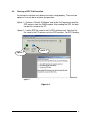
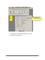
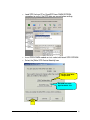
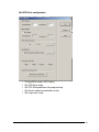
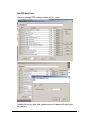
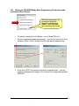
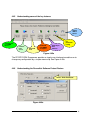
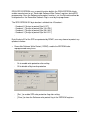
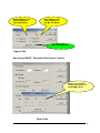
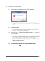
1
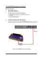
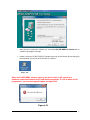
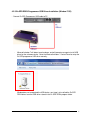
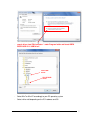
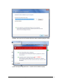
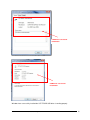
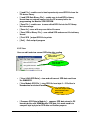
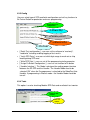
Ez-SPD
Ez-SPD
DDR4
Programmer
User’s Manual
Support Window XP, Window 7
CST Inc 2336 Lu Field Road, Dallas, TX 75229 U.S.A
Tel 972-241-2662 * Fax 972-241-2661
[email protected]
www.simmtester.com
EZ-SPD DDR4 DIMM PC Interface Control
EZ-SPD-DDR4 PC Interface
1.0
Introduction
Thank you for purchasing the Ez-SPD DDR4 DIMM Programmer, this quick reference contains
instruction on the proper use of your Programmer as well necessary as handling precautions. Read this
manual carefully to understand the proper use of the tester.
2.0
Unpacking and Inspection
Every precaution has been taken to ensure that your tester reaches you in full operational
Condition. If there is any damage to the package, please notify CST or the agent where the unit
Was purchased from immediately. Returned item must be shipped in original packaging material.
Upon unpacking, inspect the unit for any obvious physical damage. If any damage is evident,
DO NOT attempt to operate unit. Notify CST or the agent where the unit is purchased from
immediately and return item to CST or your local Authorised Representative for repair or
Replacement. (keep carton, foam inserts and packaging in the event that the unit has to
Returned to CST.)
3.0 Tester Description
86%3RUW
&RQQHFWVGLUHFWO\WR3&
86%SRUWIRU
SURJUDPPLQJ
LED Status
Indicator
Clear lighted
indication with
buzzer
Function Key
One button key
function selection
(]63'''5SLQ3URJUDPPHU
EZ-SPD DDR4 DIMM PC Interface Control _V1.0
Test Socket
288pin Test Socket
2
4.0 Ez-SPD DDR4 Programmer Description
What you will need :
•
•
•
4.1
Ez-SPD DDR4 Programmer
Ez-SPD DDR4 PC Interface Kit
Personal Computer (PC) with system requirements of
♦ AMD or Intel Pentium base PC ( Mac not supported)
♦ Microsoft Windows XP, Window 7 ( Window 8 not supported yet)
♦ 1GB RAM
♦ at least 100 MB hard drive space
♦ VGA or better video display
HARDWARE INTERFACING PREPARATION
Connect the standard USB cable to the EZ SPD DDR4 USB port located at the rear of the
programmer, the other end of the connector is connected to available Printer Port on your PC.
Figure 4-0 : EZ -SPD DDR4 PC Interface Control Setup.
EZ-SPD DDR4 DIMM PC Interface Control _V1.0
3
4.2
EZ SPD DDR4 SOFTWARE SETUP PREPARATION
4.2.1 System Check
The Ez-SPD Programmer software runs on the Microsoft Window environment and support Win
ME, Window 2000, Window Server, Window XP and Window 7.
-- Window 8 is not supported yet.
-- Do not plug in Ez-SPD DDR4 programmer to the PC USB port
4.2.2 Ez-SPD DDR4 Programmer Software Installation (Window 7 OS)
Before you install the EZ-SPD DDR4 PC software, make sure you have approximately 100
Megabytes of memory space available on your hard drive.
•
Go to Window Explorer, select the drive location which you have Ez-SPD-DDR4 PC
software program. Click on "DDR4 EZSPD USB V1.1.exe" file and open it. This is a selfextracting zip program. Follow the setup instruction on screen.
•
A dialog box pops up asking you which directory you want to copy your software into. The
default directory is C:\Program file\Ez SPD USB…etc. You can change it to a specified
directory or use the default directory. Click OK to continue software installation.
EZ-SPD DDR4 DIMM PC Interface Control _V1.0
4
•
After you have installed the software, an icon labeled Ez-SPD DDR4 PC Control will be
created in the program manager.
•
Double click on the Ez-SPD DDR4 PC Control icon brings up the Startup Screen displaying
the information and version of the Ez-SPD PC software.
Figure 4.21
When the Ez-SPD DDR4 software starts up for the first time, it will search for a
hardware connection between the PC and the Ez programmer. If it fail to detect the Ez
programmer – an error message will appear see figure 4.23
Figure 4.23
EZ-SPD DDR4 DIMM PC Interface Control _V1.0
5
4.2.3 Ez-SPD DDR4 Programmer USB Driver Installation (Window 7 OS)
- Connect Ez-SPD Programmer USB cable to PC
-
Microsoft window 7 will detect new hardware ,and will prompt message to install USB
driver for the unknown device. Go to the Microsoft window – Control Panel to setup the
Ez-SPD programmer USB driver correctly.
Window does not recognized the USB device, next step is to installed the Ez-SPD
DDR4 driver from the USB driver stored in the Ez-SPD DDR4 program folder.
EZ-SPD DDR4 DIMM PC Interface Control _V1.0
6
-
search driver from “My computer “ under Program folder and locate DDR4
EXSPD USB V1.1/USB driver/
Win7 USB
driver
Win-XP USB
driver
-
Select Win7 or Win XP accordingly to your PC operating system
-
Select x64 or x86 depending on the PC hardware and OS.
EZ-SPD DDR4 DIMM PC Interface Control _V1.0
7
- Window 7 will search for the Ez-SPD USB driver from the following program, folder
- Ignore warning message and select : Install this driver software anyway
EZ-SPD DDR4 DIMM PC Interface Control _V1.0
8
- USB driver software begins installation
USB driver successful
installation
-
Windows have successfully installed the CST EZ-SPD USB driver
EZ-SPD DDR4 DIMM PC Interface Control _V1.0
9
USB driver successful
installation
USB driver successful
installation
Windows have successfully installed the CST EZ-SPD USB driver is working properly
EZ-SPD DDR4 DIMM PC Interface Control _V1.0
10
-
Windows have successfully installed, the CST EZ-SPD USB driver is working properly
-
Run the EZ-SPD DDR4 program , Double Click
-
Windows able to detects USB driver and starts EZ-SPD DDR4 program
EZ-SPD DDR4 DIMM PC Interface Control _V1.0
11
EZ SPD DDR4 programmer is ready for operation
EZ-SPD DDR4 DIMM PC Interface Control _V1.0
12
4.3
Features
Figure 4.31
The EZ PC software provides - 4 main selection in the Ez software :
1) File
4.31
2) View
3) Config
4) Tool
File
A user can load, create a new file, save and print SPD device file.
Create a new file
Load file from saved library
Load SPD from Binary File
Save SPD into Library
Exit Program
Print SPD
•
[ New File ] : create a new SPD data from zero
EZ-SPD DDR4 DIMM PC Interface Control _V1.0
13
•
[ Load File ] : enable user to load a previously saved SPD file from the
PC device library
•
[ Load SPD Data Binary File ] : enable user to load SPD in binary
format from an external source into the PC memory buffer for
programming the Module SPD EEPROM
•
[ Save File ] : enable user to save edited SPD file into the PC library
for future usage.
•
[ Save As ] : save with any user define file name
•
[ Save SPD to Binary File ] : save edited SPD and convert file to binary
format
•
[ Print SPD ] output SPD file to printer
•
[ Exit ] : Exit and quit program
4.3.2 View
User can edit and view current SPD data after reading
View & edit current
SPD definition
View all SPD data
from module
•
[ View & Edit SPD Data ] : view and edit current SPD data read from
the DIMM SPD
•
[ View Module SPD File ] : view SPD file from byte 0 – 512 either in
Hexadecimal or decimal format
View and compare SPD
data from Buffer with
Module SPD
•
[ Compare SPD Data to Module ] : compare SPD data stored in PC
memory buffer with DIMM Module SPD data, this mode enable to
compare byte by byte for SPD data verification purpose.
EZ-SPD DDR4 DIMM PC Interface Control _V1.0
14
4.3.3 Config
User can select type of SPD read/write configuration and set key functions to
Ez-Pusher Button for production and mass programming.
Assign Batch test
configuration
Set SPD Mask Range
Set SPD Write parameters
Set Ez Button function
Handler enable
•
[ Batch Test configuration ] : user can set the software to “read only”,
“read/write” including enabling logging of test results.
•
[ Verify SPD Data ] : user can set which byte range to mask-out or skip
reading during SPD read
•
[ Write SPD Data ] : user can set all the programming /write parameter
•
[ Assign Ez Button Configuration ] : user can set function to Ez-button
•
[ Handler Interface ] This Mode is designed for making proper interface
between the EZ-SPD and the Handler. The Handler Mode need to be
selected “ON” when the Ez-programmer is attached to the RoboFlex Auto
Handler. If programming in Manual mode – the Handler Mode should be
turn off
4.3.4 Tools
This option is use for checking Module SPD Data and reset batch test counter
Verify all SPD
attribute
Rest test
counter
EZ-SPD DDR4 DIMM PC Interface Control _V1.0
15
4.4
Running a SPD Trial Execution.
Assuming the interface and software has been setup properly. There are two
options a user can do to selection the operation.
Option 1 – Perform a “Read & ID Module” and let the Ez-Programmer read the
SPD contents from the DIMM module. After reading the SPD, the data
can be files saved on the PC.
Option 2 – Load a SPD file saved in the Ez-SPD software itself. Note that the
file saved in the PC contains only the SPD contents. For SPD Reading,
Option -2
Option -1
Editing and Writing, the user has to repeat the steps as mentioned in
option 1.
Figure 4.4
EZ-SPD DDR4 DIMM PC Interface Control _V1.0
16
4.41
Option 1: Read SPD from DDR4 DIMM memory
Select
Icon
To
read
SPD
New SPD data read
from DIMM EEPROM
Figure 4.41
•
Insert module on Ez-SPD DDR4 programmer test socket
•
Select [Read & ID Module] icon
EZ-SPD DDR4 DIMM PC Interface Control _V1.0
17
Scroll
button
to view
entire
512
bytes
content
The SPD data will appear in a window box [ select “see detail”] to view the
entire SPD data before saving into a file.
4.42
Writing the SPD EEPROM by File Loading (manual mode)
EZ-SPD DDR4 DIMM PC Interface Control _V1.0
18
•
Load SPD file from PC or Read SPD from DIMM EEPROM,
remember to verify if the SPD data are correct before writing.
•
Insert DDR4 DIMM module on test socket with blank SPD EEPROM.
•
Select the [Write SPD Data to Module] Icon
Edit Ez- Read/Write
configuration
Edit SPD data from
byte location 0- 512
Start
Write
EZ-SPD DDR4 DIMM PC Interface Control _V1.0
19
Edit SPD Write configuration:
o
o
o
o
o
Change Write range [ 0-512 bytes ]
Set SPD Mask range
Set SPD Write protection after programming
Set Serial number for production testing
Set Page write sizing
EZ-SPD DDR4 DIMM PC Interface Control _V1.0
20
Edit SPD Data Field
User may change SPD settings anytime on this screen
Double click on any byte field, window menu will appear with detail byte
descriptions
EZ-SPD DDR4 DIMM PC Interface Control _V1.0
21
•
The write SPD configuration table will appear and user can choose to
either [edit] the SPD or proceed to [Write the SPD] , Press [ OK ] to
start writing using the mouse.
•
A running man will appear during SPD programming – do not
interrupt the PC during writing.
•
When the Ez-SPD have successfully programmed the SPD data into
the Blank EEPROM , a result screen will appear indicating a Pass or
Failed.
EZ-SPD DDR4 DIMM PC Interface Control _V1.0
22
4.43 Writing the SPD EEPROM by Batch Programming (Production mode activation by Push Button)
The Ez-SPD programmer can
be interfaced to the CST –
RoboFlex1 and RoboFlex2
Handler – select this option
when interfacing with handler
•
The default setting for the Ez-Button is set to “Read SPD only” .
•
For mass production programming mode – user must assign the Ez-Push
Button to “Write & Verify” for both Handler and manual programming.
•
Once the Ez-SPD Push button have been assigned to write – you can
continue to proceed with chapter 1.42 and start mass programming blank
EEPROM.
EZ-SPD DDR4 DIMM PC Interface Control _V1.0
23
4.44
•
Editing the SPD EEPROM Data
There two ways to edit the SPD data – see figure 1.44a and figure 1.44b, both
selection will take you to the common SPD database location.
Figure 4.44a
Figure 4.44b
EZ-SPD DDR4 DIMM PC Interface Control _V1.0
24
By Default – SPD
data are viewed in
Hexadecimal, user
can view the SPD
data in decimal
format
Figure 4.44b
•
CST engineers have enhanced the latest EZ SPD DDR4 software version
by allowing user to select and edit each byte location with the help table
included to provide ease of editing the SPD definition
•
For example – if you select the [Detail] box at byte 0 location, the following
byte zero table will appear. Editing the table is easy – placed the mouse
cursor at the two selection , to change the SPD data. Double click the
mouse to change the SPD data and it automatically will refresh the SPD
data base with the new data. Remember to save the updated SPD data
before programming.
Place mouse
cursor to scroll to
view the rest of
the byte location
EZ-SPD DDR4 DIMM PC Interface Control _V1.0
25
4.45
Understanding some of the key features
Output
SPD to
printer
Read SPD data
from DIMM
Memory
Load file
from
saved
Edit SPD
data
Read SPD
from DIMM
& compare
Single Cycle
write
SPD into
For
production
testing
Figure 4.45a
The EZ-SPD DDR4 Programmer provides a simple user interface to enable user to
change any configuration by a simple mouse clip. See Figure 4.45a.
4.46
Understanding the Reversible Software Protect Feature
Select “Write Protection”
Figure 4.46a
EZ-SPD DDR4 DIMM PC Interface Control _V1.0
26
DDR4 SPD EEEPROM uses a special function build in the DDR4 EEPROM chip to
enable manufacturer to set “Reversible Software Write Protect” registers during SPD
programming. Once the Software write protect function is set, the Byte data cannot be
changed unless the Reversible Software Flag is reset by the programmer.
The SPD EEPROM 512 byte location is divided into 4 Quadrant :
- Quadrant 0 [ Assign to protect Byte 0-127 ]
- Quadrant 1 [ Assign to protect Byte 128 -255 ]
- Quadrant 2 [ Assign to protect Byte 256 -383 ]
- Quadrant 3 [ Assign to protect Byte 384 -512 ]
Byte 0 to byte 511of the SPD are protected by RSWP, user may choose to protect any
quadrant number.
•
Reversible Software Write Protect ( RSWP), enable the EEPROM to be
reprogrammed many times
-
On to enable write protection after writing.
-
Off to disable all byte write protection
-
[ Set ] to enable SPD write protection flag after writing.
-
[ Clear ] to clear the Software write protect flag in the EEPROM registers
EZ-SPD DDR4 DIMM PC Interface Control _V1.0
27
Enable Software write
protect Register to
byte Q0,Q1,Q2,Q3
Clear Software write
protect Register to
byte Q0 , Q1, Q2,Q3
Write EEPROM Button
Figure 4.46b
How to clear RSWP “ Reversible Write Protect” feature.
Enable user to disable the
“Software Write protect” in
the EEPROM registers.
Figure 4.46c
EZ-SPD DDR4 DIMM PC Interface Control _V1.0
28
From the above menu Figure 4.46c – be very careful when selecting the Write protect
selection, if you are unsure, please consult the EEPROM manufacturer for more
details before selecting the “write protect registers”. Before programming the
EEPROM, you can decide to choose whether to to RSWP registers, do not select the
SPD write protect menu if you are unsure.
Software Write protect error messages during programming
Clear RSWP registers
successfully. EEPROM
can be reprogram
again
Unable to set RSWP
registers after
programming.
EZ-SPD DDR4 DIMM PC Interface Control _V1.0
29
5. Quick Guide with Examples
This chapter will guide you through a simple example with a known DDR4 DIMM
module to help you get familiar with the EZ-SPD DDR4 SPD functions. If you should
have any doubt on the menu options, please refer back to the previous chapter on
operations basics for a detailed explanation.
The examples illustrated in this section use a standard 284pin 8GB DDR4 Unbuffered
DIMM memory module.
EZ-SPD DDR4 DIMM PC Interface Control _V1.0
30
5.1
Read SPD
•
Insert DIMM into Ez-SPD Programming test socket and select [Read and ID
Module]
•
Saved DIMM SPD results.
EZ-SPD DDR4 DIMM PC Interface Control _V1.0
31
•
Verify to ensure that the SPD Data is correct.
EZ-SPD DDR4 DIMM PC Interface Control _V1.0
32
•
Set Batch Test functions using the icon- select [ Write & Verify ]
•
Setup SPD programming parameters
Edit Read/write
configuration
Editing the SPB
byte from Byte 0 511
Edit programming
configuration – such as
Byte range, Mask off range,
write or read only function
•
Insert Module - Press the Push Button on the Ez-SPD DDR4 Programmer
to start programming
•
Test results will be output to Monitor screen , insert next module for
programming
EZ-SPD DDR4 DIMM PC Interface Control _V1.0
33
6.0
TROUBLE- SHOOTING GUIDE
6.1
Software error – cannot detect Ez-SPD DDR4 Programmer
•
6.2
6.3
6.4
Check all Cable and USB connections between Ez-SPD programmer
and PC
Cannot Read SPD
•
Ensure module is properly inserted and aligned in the test socket.
•
If all fails – contact CST for Tech Support
Error Message – “ WAITING FOR HANDLER START” ... .if handler is
being interfaced
•
Ensure that the Handler interface cable is connected to the front side
of the handler which have a 20pin Female mating connector.
•
Set the handler Mode setting : Sampling rate = 2200ms , Sort =
2000ms for optimum setting
For other queries, contact CST Technical Support Hotline.
END
EZ-SPD DDR4 DIMM PC Interface Control _V1.0
34