1
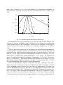
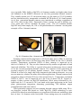
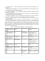
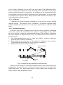
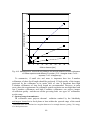
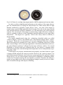
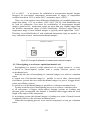
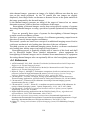
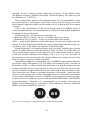
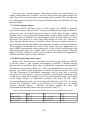
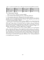
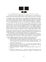
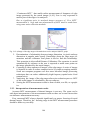
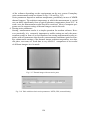
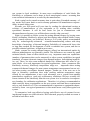
“Continuous MTF” that enable online measurement of sharpness of edge
image generated by the tested imager [8,10]. User is only requested to
mark a part of the edge to be analyzed.
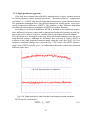
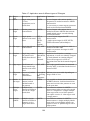
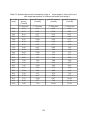
Due to significant noise in analyzed images accuracy of “Live MTF”
measurement is high and true measurement of MTF must be made later
using some noise reduction methods.
a)
b)
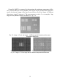
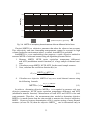
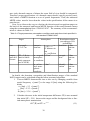
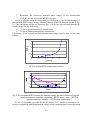
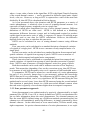
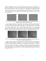
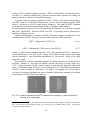
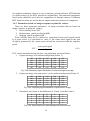
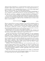
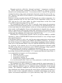
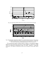
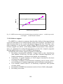
Fig. 5.12. a)Image of the edge target with marked area to be analyzed b)MTF graph.
5. Determination of relationship between image dimension in pixels and true
dimension in angular units (mrad). Knowledge about the edge target dimensions and the collimator focal plane is used to find this relationship.
This operation is often called Distance Calibration. The operation is carried
automatically by software or the user is expected to mark some points on
the image generated by the tested imager.
6. Capturing a video sequence of images of the edge target. A series of images
is captured in order to reduce temporal noise by simple averaging method.
Some test computer programs use also more advanced image processing
techniques that can reduce additionally high frequency spatial noise fixed
pattern noise).
7. Analyzing the image of the edge target after noise reduction process. MTF
of the tested imager is calculated by the test software.
8. Storing the MTF measurement results in form of table, text file, or a graphics.
5.2.3 Interpretation of measurement results
Accurate MTF measurement of thermal imagers is not easy. The same can be
said about interpretation of the measurement results as there are several factors that
can influence measurement accuracy.
First, measured MTF always depends significantly on proper focusing of tested
thermal imager. Therefore, the focusing stage in the MTF measurement procedure
should be done very carefully.
146