1
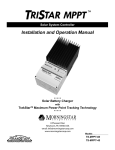
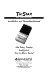
First in Finishing!
HZ-SERIES
User Manual
Mass Finishing Inc.
1060 Commerce Blvd.
Howard Lake, MN. 55349
Toll Free: 888-260-6277
Phone: 320-543-3222
FAX: 320-543-3355
Internet: http://www.massfin.com
©2005 Mass Finishing Inc. – All Rights Reserved
This manual may not be reproduced in any form without the express, written consent of Mass Finishing Inc.
HZ-SERIES User Manual
Introduction
This manual covers the installation, operation and maintenance of our HZ-SERIES
machines. The Mass Finishing, Inc. HZ-SERIES Finishing/Polishing Centrifugal Barrel
Machine is comprised of four individual barrels mounted on the periphery of a
turret. The turret is rotated in one direction, causing the barrels to rotate in the
opposite direction. This action is due to either a Timing Belt, V-Belts or Chain that
is connected between the main shaft and the centerline of the 4 barrels. In
operation, this turret rotation creates a high centrifugal force. This force
compresses the load into a tight mass causing the media and parts to slide against
each other removing burrs and creating a superior finish. Short cycle times are
realized as a result of the high centrifugal energy being applied to the parts.
At MFI, our goal is complete customer satisfaction. We pride ourselves on our
commitment to our customers both before and after the sale.
Contact Information
Shipping/BillingAddress:
Mass Finishing Incorporated
1060 Commerce Blvd.
Howard Lake, MN. 55349
Toll Free:
Direct:
Fax:
(888) 260-6277
(320) 543-3222
(320) 543-3355
Email:
[email protected]
Internet:
http://www.massfin.com
Company Personnel
President:
Vice President:
Office Manager:
Technicians:
Mike Mathisen
Tommy Mathisen
Marci Theisen
Paul Zellmann
Mass Finishing Inc.
1
HZ-SERIES User Manual
Certifications
The HZ-SERIES machines carry the CE mark of certification and is fully compliant
with all standards prescribed below.
Declaration of Conformity
EC Declaration of Conformity according to
EC Machinery Directive 98/37/EC, Annex II A
We herewith declare,
Mass Finishing, Inc.,
1060 Commerce Boulevard
Howard Lake, MN 55349
that the following machine complies with the appropriate basic safety and health
requirements of the EC Directive based on its design and type, as brought into
circulation by us. In case of alteration of the machine, not agreed upon by us, this
declaration will loose its validity.
Machine Description:
Finishing/Polishing
Centrifugal Barrel Machine
Machine Type:
HZ-Series
Applicable EC Directives:
EC Machinery Directive 98/37/EC
EC Low Voltage Directive 73/23/EEC
EC Directive of Electromagnetic Compatibility
89/336/EEC
Applicable Harmonized Standards: See quote issued by TÜV
Typically:
EN 1050, EN 292-1, EN 292-2, EN 294
EN 349 (mechanical)
EN 60204-1 (low voltage, electrical)
EN55011, EN 50082-1 (EMC)
Applicable National Standards:
e.g. UL1950, ANSI... OSHA
Third party tested by:
TUV PRODUCTS SERVICES.
Date/Authorized Signature:
Michael D. Mathisen
________________________June
30, 1999
Title of Signatory:
CEO, President
2
Mass Finishing Inc.
HZ-SERIES User Manual
MFI “5-2-1” Warranty
MASS FINISHING INC.
“WARRANTY PLUS” 5 -- 2 – 1
MASS FINISHING INC. warrants that if any part of our product, which has been properly maintained
and which is used under normal operating conditions in the plant of the original purchaser, proves to be
defective in material or workmanship, it will be replaced free of charge and shipped prepaid using
standard UPS or truck and installed at the expense of the purchaser. The schedule is as follows:
FIVE (5) YEAR WARRANTY or 10,400 hours, whichever comes first:
Any part manufactured to MFI specifications, such as frames, brackets, casting, weldments.
TWO (2) YEAR WARRANTY or 4,160 hours, whichever comes first:
All component parts not manufactured by MFI such as electrical control devices (Relays, Starters).
Warranty on motors and variable frequency drives is subject to manufacturer’s warranty as offered.
ONE (1) YEAR WARRANTY or 2,080 hours, whichever comes first:
Expendable parts such as bearings, v-belts, timing belts, barrel liners, discs, reducers and pumps.
Warranty will be prorated on the expendable portion of parts on a one-year life.
Mass Finishing Inc. shall not be responsible for work done, material furnished, or repairs made by
others unless agreed to in writing. We reserve the right of performing or supervising any repair work
necessary to put equipment in proper operation under this warranty.
EXCEPT AS STATED ABOVE, THERE ARE NO WARRANTIES, EXPRESS OR IMPLIED,
INCLUDING THE WARRANTIES OF MERCHANTABILITY AND FITNESS FOR A
PARTICULAR PURPOSE. MASS FINISHING INC. ACKNOWLEDGES THAT PURCHASER’S
SOLE AND EXCLUSIVE REMEDY AGAINST COMPANY SHALL BE FOR THE REPAIR OR
REPLACEMENT OF DEFECTIVE PARTS AS PROVIDED FOR HEREIN AND THE WARRANTY
AS STATED ABOVE IS IN LIEU OF ANY OTHER WARRANTY OR REMEDY. IN NO EVENT,
BE IT DUE TO A BREACH OF ANY WARRANTY OR ANY OTHER CAUSE ARISING FROM
THE PERFORMANCE OR NON-PERFORMANCE OF THE GOODS SOLD THEREUNDER,
SHALL MASS FINISHING INC. BE OBLIGATED OR LIABLE TO PURCHASER IN ANY
MANNER FOR CONSEQUENTIAL OR INCIDENTAL DAMAGES, INCLUDING, BUT NOT
LIMITED TO, LOST PROFITS, PLANT DOWNTIME OR SUITS BY THIRD PARTIES.
RETURNS
1.
Copy of Invoice or copy of Replacement Item Packing Slip must accompany all returned goods.
2.
Returned goods are subject to a 15% restocking charge.
3.
All returns must be shipped prepaid.
4. Machine orders canceled shall require a cancellation charge of 10% to 70%, depending upon
amount of work completed and the series of machine ordered.
Mass Finishing Inc.
3
HZ-SERIES User Manual
Machine Safety Precautions
!
Please review these Safety Precautions carefully! Always follow accepted
Safety practices whenever operating or servicing this machine. Failure to adhere
to these precautions could result in severe personal injury and or death!
These instructions should be read and understood by all persons who will be
installing, operating or maintaining the machine.
1. ALWAYS disconnect power supply before doing maintenance, servicing or
cleaning the machine.
2. NEVER attempt to clean, lubricate or repair the machine while it is in
motion.
3. KEEP hands, feet and clothing away from all moving parts such as belts and
flywheels.
4. KEEP all guards, covers, and doors in place at all times.
5. DO NOT remove warning/advisory decals and labels from machine.
6. KEEP hands and feet clear of any pinch points.
7. NEVER use any combustible solvents in the machine. Flash fire or explosion
may occur.
8. ALWAYS lock barrel covers securely in place before operating machine.
9. NEVER operate the machine with missing and or loose barrel covers.
10. ALWAYS stay clear of the machine when jogging the turret. Keep loose
articles of clothing such as ties, lab coats etc. away from turret.
11. This machine must be installed following all applicable local and National
Electrical Codes. Whether this is the NEC Code 250, CSA Codes or European
Code BS7671. IEEE wiring regulations- 16th addition.
12. Any Electrical maintenance should always be performed by a qualified
Electrician.
4
Mass Finishing Inc.
HZ-SERIES User Manual
13. WARNING: Barrels may be under extreme pressure. ALWAYS open barrels
slowly to allow any built up pressure to vent slowly before opening the
barrel completely.
14. DO NOT operate the turret motor at slow speeds for extended time periods.
Doing so can/will cause the turret motor to overheat causing irreparable
damage.
15. AT NO TIME should the machine be operated at full speed for 30 minutes or
more with ANY MEDIA weighing over 100 lbs. per cu. Ft. Failure to heed this
warning will result in extreme internal barrel temperatures and pressure
accumulation.
16. DO NOT operate the machine without at least 2 barrels loaded into the
turret. If you intend to operate a single barrel, please ensure that you have
another barrel mounted directly across from it to serve as a counterbalance.
The other barrel can be filled with water and media.
NEVER force the hood open! The machine is equipped with a locking safety switch.
The hood may only be opened once power has been applied to the machine and the
Green; “Master Start” pushbutton has been energized. During operation, the hood
may only be opened whenever there is not a machine cycle in progress.
Mass Finishing Inc.
5
HZ-SERIES User Manual
Section 1: Machine Installation
Machine Inspection
The machine was shipped to you in a protective wooden crate. Please inspect the
machine carefully immediately upon arrival. If you notice any sign of damage,
notify your carrier and follow appropriate procedures.
Machine Documentation
The documentation for the machine is located inside the Electrical enclosure
mounted on the right side of the machine.
Documentation includes:
1. This manual
2. A Manual for the Variable Frequency Drive that operates the turret
Please remove the documentation and store it in a safe location.
Machine Installation
1. Carefully remove the machine from its protective crate.
2. Remove any protective wrapping from the machine.
3. Place the machine on a firm, level surface.
a. Due to the nature of this machine, it is very important that it be
leveled as accurately as possible.
b. The machine is equipped with leveling bolts. If necessary, adjust the
machine leveling bolts using a 15/16” wrench.
4. Connect AC Power to the machine.
a. Refer to the Electrical Specifications for recommended supply
current.
b. If the AC power is subject to frequent sags and or surges, it may be
necessary to install an isolation transformer to supply the machine
with power. Please call MFI if you have any questions.
6
Mass Finishing Inc.
HZ-SERIES User Manual
c. This work should be performed by a qualified and licensed
Electrician.
d. Refer to the “Electrical Panel Layout” diagram for the location of
power lead termination into the Electrical cabinet.
5. For convenience, locate the machine somewhere in close proximity to a
water supply.
Mass Finishing Inc.
7
HZ-SERIES User Manual
Section 2: Machine Operation
Machine Controls
Shown below in Figure 1 is a picture that indicates the location of the various
controls on the machine.
Turret Speed
Indicator
Cycle Start
Button
Programmable Timer
Jog Button 2
000
Turret Speed
Control
End of Cycle Buzzer
Timer/Buzzer Reset
Button
Turret Direction
Switch
Master Start Button
Cycle Stop
Button
Emergency Stop
Button
Jog Button 1
HZ/30-40 Operator Control Panel
Figure 3
Operating the Machine in “Jog” mode
1. Apply power to the machine by pressing the Green, “Master Start”
pushbutton.
2. Once power is applied, you can check the operation of the hood safety
switch by opening the hood.
a. If you cannot open the hood, and the Master Start button is
illuminated, refer to the Troubleshooting section of this manual for
suggestions. DO NOT force the hood open.
3. To Jog the machine, you must press both of the Jog buttons
simultaneously. The turret will rotate at slow speed for as long as you have
both of the buttons pressed.
8
Mass Finishing Inc.
HZ-SERIES User Manual
Running a Timed Cycle
Adjusting the Timer
As the name implies, a Timed Cycle is going to utilize the Programmable Timer that
is mounted to the machine control panel. Refer to the procedure below for making
adjustments to the timer.
Cycle Time Display
Area
8.8:8.8
Cycle Time Adjustment
Display
8.8:8.8
MODE
4
3
2
1
Time Adjustment
Keys
RST
Figure 4
Figure 4 shows the layout of the Cycle Timer. This timer is preset at the factory to
be a “Count Down” timer with a maximum time of 99 minutes.
Each digit of the timer is controlled with its corresponding Time Adjustment Key as
shown in the diagram. The Time Adjust keys are 2 position rocker switches. Pressing
the top of the key will increase the time for that digit and pressing the bottom of
the key will decrease the time.
To program a Cycle Time of 20 minutes:
1. Press the top of the adjustment key for digit 1 until it shows a 0 (zero).
2. Press the top of the adjustment key for digit 2 until it shows a 2.
3. Press either the “RST” key on the timer itself or the “Timer Buzzer Reset”
pushbutton on control panel to reset the cycle time to the value you’ve
programmed.
Mass Finishing Inc.
9
HZ-SERIES User Manual
Adjusting the Machine Speed
The rotational speed of the turret is adjusted using the rotary potentiometer
labeled “Drum Speed” on the machine control panel. Refer to Figure 3 for the
location of this potentiometer.
The minimum speed of the machine is approximately 10 RPM and the maximum
speed is 225 RPM.
NOTE: Running the machine at low speed for sustained periods of time is not
recommended and may damage the main turret motor.
Rotating the knob CW will increase the rotational speed of the turret. Rotating the
know CCW will decrease the speed of the turret.
Starting the Cycle
To start a Timed Cycle:
1. Ensure that the hood is fully closed.
2. Press the yellow “Cycle Start” button.
a. NOTE: If the machine does not start, please refer to the
Troubleshooting section of this manual for suggestions.
3. The machine will continue to operate at the selected speed for the time
programmed.
4. The Cycle may be stopped at any time by pressing the red “Cycle Stop”
pushbutton.
Adjusting Turret Direction
The turret can be operated in either the forward or reverse direction. The direction
of rotation does not have any bearing on the processing of the part.
To change the rotational direction of the barrel, use the 2 position selector switch
labeled “Drum Rotation”. Refer to Figure 1 for the location of this switch.
“FWD” is defined as the turret rotating towards you. “REV” is defined as the turret
rotating away from you.
10
Mass Finishing Inc.
HZ-SERIES User Manual
Section 3: Finishing Parts
Using Media
The quantity of media and parts that comprises a barrel load is measured by
volume and is stated as a ratio. A ratio of 3:1 means that there are three parts by
volume of media and one part by volume of parts.
The number of parts that can be processed at one time in a barrel is dependent on
the physical nature of the part and its final desired state. For some parts, this may
allow the desired results to be obtained by self-tumbling or self-vibrating; that is,
finishing the parts without any media. The physical nature and desired results on
other parts may require them to be processed at ratios of 6:1 or 7:1, and
occasionally even higher.
The lower the ratio, the more likely it is that the parts will come into contact with
each other during the course of processing. This is called “part impingement”.
Some parts, due to design or desired results, can withstand considerable selfcontact during the course of processing. Other parts made of soft materials and
requiring a low microinch surface with no nicks will require a higher degree of
protection from the media. Generally, precision machined or ground parts and
parts that are being prepared for decorative plating are processed at the higher
ratios, as are parts that are fragile or that have a tendency to nest or entangle.
When too many parts are in a barrel, they can interfere with each other. This
condition prevents the media from having free access to internal areas that require
work or to inside areas where the direction of the plane changes.
A method of estimating the quantity of parts per barrel load for sample processing,
or a first time production cycle, is the box volume method. This method is
excellent for estimating formed stampings, machine parts, die castings and some
larger parts. For example, suppose a part is 3 inches high, 3 inches wide and 3
inches deep. For estimating purposes, the total volume of the part would be 27
cubic inches. That is, the volume of the smallest box that would contain the part is
27 cubic inches. Screw machine parts, rivets, and some other small parts can be
estimated by bulk or by the size of the container in which they are packaged.
There are 1,728 cubic inches in a cubic foot (12” x 12” x 12”); therefore, 64 parts
would occupy a cubic foot of space (1728/27).
Assume that a 4 cubic foot capacity barrel (model HZ-120) will be used to finish the
parts, and that a 60% fill level with a 3:1 ratio will be used. Sixty percent of the 4
cubic foot compartment equals 2.4 cubic feet for the work load. With a 3:1 ratio of
media to parts, the media would occupy 1.8 cubic feet and the parts would occupy
.6 cubic feet. With 64 parts per cubic foot, the work load would contain 38 parts
(.6 x 64).
Mass Finishing Inc.
11
HZ-SERIES User Manual
A 60% fill level was used in the barrel because some settling of the work load may
take place after a few revolutions and will bring the total work load close to 50%
which offers the greatest length of slide in the rotating barrel and hence, is the
most efficient.
Many parts containing open areas, such as tubing or open ended, box-formed parts,
will fill with media within a short time after starting a cycle. This condition will
usually allow an additional number of parts to be added to the work load.
By experimenting with various media types and the cushioning effects of
compounds, and by regulating the forces which drive the media, the number of
parts that can be processed at one time can often be increased. Every extra part
that can be included in the work load will reduce the processing costs associated
with each part.
Media-Parts Ratio Examples
RATIO
0:1
Part on part. Used for knocking off burrs. No media required.
1:1
Deburring only, leaves very rough surfaces.
3:1
Still considerable part on part, but good for most ferrous
metals.
5:1
Good for non-ferrous metals. Minimal part impingement.
8 : 1 to 15 :1
For high quality finishes.
No contact
1 part per barrel. Provides superior finishes.
Choosing Tumbling Media
MFI stocks and sells tumbling media and compounds from all of the leading
manufacturers as well as media that we manufacture ourselves. For your
convenience, you may view some of these products on our website at
http://www.massfin.com.
Choosing the correct tumbling media for your finishing process can be a difficult
task. Most mass finishing processes require more than 1 step to complete.
To use an analogy, a mass finishing process is much like the process that is required
to produce a smooth finish on a piece of wood that is going to be used for furniture.
12
Mass Finishing Inc.
HZ-SERIES User Manual
First, the piece of raw wood must be rough sanded using a coarse grade of
sandpaper to remove any saw marks. Once the wood has been rough sanded,
medium grit sandpaper is used on it to remove any leftover marks or grain
irregularities. In a mass finishing process, these steps would be referred to as the
Cutting/Deburring steps. The type of media that is used during these steps is
usually either a Plastic or Ceramic media if the material is metal, or if the material
is rubber or silicone, a Porcelain media may be used instead.
Next, fine grit sandpaper would be used to prepare the wood to receive stain. This
step would be called the Pre-plate step in a mass finishing process. Like wood, the
metal must have a smooth, uniform surface prior to any type of chroming or
anodizing process. During this step, a Plastic material is normally used.
Finally, the wood is ready for a finish coat. In a mass finishing process, this step is
called the Polish step. During this step, a dry media such as one of our Corn Cob
blends is used to produce a deep, high luster shine on the material being processed.
Shapes, Sizes and Compositions
Tumbling media is available in a wide variety of different shapes, sizes and
compositions.
The shape of the media chosen for the process is determined largely by the type of
work to be performed and the physical properties of the piece being processed.
Refer to the chart below for an example of the most common shapes of media.
Cones
Triangles/Pyramids
Cylinders
Spheres
Specialized shapes such as Angle Cut Cylinders, Tetrahedrons, TriStars and
Ellipses are also available.
Mass Finishing Inc.
13
HZ-SERIES User Manual
Referring back to the furniture analogy, the composition of the media can be
thought of as it's "grit". Just as there is a wide variety of media shapes available,
there is also a wide variety of compositions too.
MFI stocks media from all of the major media manufacturers. Each manufacturer
has a unique way of describing composition. The table below shows some of our
more commonly requested compositions.
Media
Type
Ceramic
Plastic
14
Composition
Characteristics
30, D-30,
Dura30
Good for cutting and deburring. Fast metal removal.
Medium wear rate.
F33
High density, general purpose cutting and deburring.
Good wear rate.
AX-65
Fast cutting. Medium wear rate. Good for medium
and heavy burr removal.
AX-90
Good general purpose media. Long wear life. Good
for burnishing.
H-33
High density, medium cut, long life. Works well
in high energy machines.
WK
Fast cutting, very durable. Well suited for high
energy machines.
XF
Extra fast cutting. Moderate wear rate.
SJ
Light weight, long lasting, fast cutting.
RG
Special forumlation. Good for pre-plating. Medium
wear rate.
#2000
Good cut and wear rate. Produces a galvanized style
of finish. Well suited for pre-plating.
#2050
Slower cut rate than #2000. 12% longer life.
#4000 M2
Long life, medium cut rate. Low foaming
composition.
#4000 M4
Produces a low luster finish compared to #4000 M2.
Excellent pre-plating media. Medium foam.
Mass Finishing Inc.
HZ-SERIES User Manual
Loading and Unloading Barrels
Removing a Barrel from the Cradle (HZ-12,40)
To remove a barrel from the cradle:
1. Loosen the 2 set screws on the lock down bar using the “T” handle Allen
wrench that was provided with the machine.
2. Slide the lock down bar to the left or right, then lift the opposite end of the
bar such that it can be removed from the cradle.
3. Grasp the handles on the barrel and remove it from the cradle.
Removing a Barrel from the Cradle (HZ-30 2S)
To remove a barrel from the cradle:
1. Loosen the bolt on the lock down bar.
2. Slide one end of the lock down bar left or right, then lift the opposite end of
the bar such that it can be removed from the cradle.
3. Grasp the handle on the barrel and the handle on the lid. Remove barrel
from the cradle.
Removing the Barrel Lid (HZ-12,40)
!
NOTE: USE EXTREME CAUTION WHEN REMOVING THE BARREL LIDS AS THE
CONTENTS OF THE BARREL MAY BE UNDER EXTREME PRESSURE!
1. The lid is secured to the barrel using 3 spring clips. Only release 1 of these
clips at a time to allow any pressure to escape gradually.
a. NOTE: For best results, stand the barrel on end before releasing any
of the clips.
2. Remove all 3 clips and remove the lid from the barrel exposing the contents.
Mass Finishing Inc.
15
HZ-SERIES User Manual
Removing the Barrel Lid (HZ-30 2S)
1. The lid is secured to the barrel using 2, lever action cam handles and 2,
spring lock pins.
2. Begin by grasping a spring pin and pulling it towards the center of the lid.
This will remove the safety pin from the cam handle.
3. Rotate the spring pin 90 degrees upwards so that it stays in the removed
position.
4. Repeat steps 2 and 3 for the second spring lock pin.
5. Using the barrel latch tool that was supplied with the machine*, insert one
end over the lever end of the cam handle.
a. *The barrel latch tool is a round pipe approximately 12” long and 1”
in diameter. Please contact MFI if you did not receive one with your
machine.
6. Carefully lift the lever until it is approximately half-way released.
7. Repeat steps 5 and 6 for the opposite cam handle lever.
8. Once both cam handle levers are released half-way, fully open both cam
handle levers.
9. Slide each cam handle lever towards the middle of the barrel lid. This will
disengage the cam handle from the cam handle bracket on each end of the
barrel.
10. Remove the lid.
Loading a Barrel into the Cradle (HZ-12,40)
Before replacing a Barrel into the cradle, ensure that all 3 of the lid cover clips are
fully closed.
!
NOTE: FAILURE TO FULLY CLOSE THE BARREL LATCH CLIPS WILL RESULT IN
DAMAGE TO THE CLIP AND OR THE MACHINE!
1. The barrels are secured into the cradles using the lock down bar.
16
Mass Finishing Inc.
HZ-SERIES User Manual
2. Replace the barrel into the cradle such that it lies in the cradle with the
barrel handles oriented up. It does not matter whether the lid faces to the
right or the left.
3. Orient the notches on the lock down bar so that they are facing up.
4. Slide 1 end of the lock down bar into 1 of the slots on either end of the
cradle.
5. Lay the lock down bar flat and slide the other end into the slot on the
opposite end of the cradle.
a. NOTE: You may need to loosen the Allen screws to achieve the
proper fit.
6. Tighten the set screws on the lock down bar to a torque of 6-8 ft. lbs.
a. NOTE: Do not over tighten these screws as it will lead to premature
failure of the threads on the lock down bars.
TIP: It is only necessary to apply 6-8 ft. lbs of torque to the set screws. You may
wish to purchase a torque wrench with a 3/16th inch Allen head bit to use for this
purpose. Doing so will prolong the life of the lock down bars
Loading a Barrel into the Cradle (HZ-30 2S)
1. Ensure that the cam handles are fully released (oriented towards the middle
of the lid) and pointing up.
2. Slide the lid onto the barrel so that the cam handle pins are aligned with the
holes on the cam handle brackets on either end of the barrel.
3. Slide each cam handle pin into its hole on the cam handle bracket.
4. Using your hands, engage the pins in the brackets using even downward
pressure on each side until you cannot move them any further by hand.
5. Use the barrel latch tool to lock the cam lever handles in the fully closed
position by pressing firmly down on each of the cam lever handles.
a. NOTE: Be sure to keep the seal area around the inside perimeter of
the barrel liner free of any media that may have accumulated there.
Failure to do so will lead to improperly sealed barrels which will
cause them to leak during a cycle.
Mass Finishing Inc.
17
HZ-SERIES User Manual
6. Rotate the spring lock pins 90 degrees so that they lock into the holes on the
cam handle levers.
7. Place the sealed barrel into the cradle.
8. Slide the lock down bar into the slot on either side of the cradle.
a. NOTE: Be sure that the grooves on both ends of the lock down bar
are aligned with the slots on both ends of the cradle.
9. Tighten the lock down bar in place.
TIP: It is only necessary to apply 6-8 ft. lbs of torque to the bolt on the lock down
bar. You may wish to purchase a torque wrench with a ¾” inch socket head to use
for this purpose. Doing so will prolong the life of the lock down bars.
Removing a Barrel Lid (HZ-80, 120, 160, 220)
1. Use the “JOG” pushbuttons to move the barrel you’d like to unload into a
comfortable unloading position.
2. Prior to removing the barrel lid, use the “Barrel Rotation” switch on the
Control Panel to rotate the barrel in the REV direction for a half turn, then
FWD again to a level position. Doing so will help to even out the contents of
the barrel prior to unloading.
3. Begin by releasing the Safety Lock Pins. The Safety Lock Pins are spring
loaded. These pins engage the Cam Lock Levers on both sides of the barrel
and are used to ensure that the Cam Lock Lever stays in the locked position
during processing.
4. To remove a Safety Lock Pin, press outward on the Pin lever freeing it from
the Cam Lock Lever.
5. Rotate the Pin lever 90 degrees so that it remains in the unlocked position.
6. Using the barrel lid removal tool that came with the machine, slip one end
of the tool over the end of a Cam Lock Lever.
a. NOTE: The barrel lid removal tool is a stainless pipe. It is shipped
inside the Electrical Enclosure on most machines. Please call MFI if
you did not receive a barrel lid removal tool.
18
Mass Finishing Inc.
HZ-SERIES User Manual
7. Slowly lift the Cam Lock Lever until it is at the 45 degree position.
8. Repeat steps 2-5 for the other side.
9. Once both Cam Lock Levers are loosened, move them to the 90 degree
position while pulling them towards the center of the lid to release the Cam
Lock Levers from the Barrel Yokes on both sides of the barrel.
10. Use the Lid Lift Handles to remove the barrel lid from the barrel.
!
NOTE: USE EXTREME CAUTION WHEN REMOVING THE BARREL LIDS AS THE
CONTENTS OF THE BARREL MAY BE UNDER HIGH PRESSURE!
It is good practice to keep the lid liner clean and free of media. Spray the lid liner
off with water to prepare it for the next load.
Removing Parts onto a PSA-HZ Separator
11. If the machine is equipped with a PSA-HZ Vibratory Separator, use the Jog
buttons to rotate the turret into position such that the barrel you’d like to
unload is centered immediately over the Separator screen.
12. Turn the Separator on using the “Separator Start” button on the Control
Panel.
a. NOTE: The Separator deck is mounted to the frame of the separator
on 4 coil springs. If the Separator is making a loud “knocking” sound,
check to ensure that the deck is securely attached to all 4 springs.
13. Place 2 Media Baskets at the end of the Separator, underneath the deck.
Position the Media Baskets such that the load of media will be divided
equally between the 2 baskets.
14. Use the “Barrel Rotate” switch on the Control Panel to dump the contents of
the barrel onto the Separator.
15. Spray the inside of the barrel out thoroughly to clean any residue from the
liner.
16. Remove any media that may have lodged in the liner. Particularly from
around the perimeter of the barrel sealing gasket.
a. NOTE: Failure to remove excess material from the barrel seal will
result in leaking barrels and inefficient/ineffective processing.
Mass Finishing Inc.
19
HZ-SERIES User Manual
Loading a Barrel (HZ-80, 120, 160, 220)
17. For best results, the barrel should be filled using a “layering” technique.
Begin by filling the bottom of the barrel with media.
18. Next, add a quantity of parts. Follow with another layer of media.
19. Continue the layering process until the barrel is full of media and parts.
a. NOTE: The “full” level should be determined by the process sheet
that was supplied with the machine. Normally, a barrel is filled to
the 60-70 percent full level.
20. Add any compounds that may be required.
21. If the process is a wet process, fill the barrel with water until the level of
the water just covers the top of the media.
20
Mass Finishing Inc.
HZ-SERIES User Manual
Replacing the Barrel Lid (HZ-80, 120, 160, 220)
22. Ensure that both of the Cam Lock Levers are in the fully retracted (slid
towards the middle of the lid) position. Use the Lid Lift Handles to position
the lid back onto the barrel.
23. Grasp the Cam Lock Levers and slide the Cam Lock Pins out into the Barrel
Yokes on both ends of the barrel.
24. Pull the Cam Lock Levers toward you by hand until the Cam Locks Pins are
firmly seated in the Barrel Yokes.
25. Using the Barrel Lid tool, press down firmly on each Cam Lock Lever until
the lever is flush with the top of the barrel.
a. NOTE: For best results, apply equal pressure to both Cam Lock
Levers to ensure a good seal.
26. Insert both Safety Lock pins by rotating them until they spring into the holes
on each Cam Lock Lever.
!
WARNING! Failure to fully secure the barrel lids to the barrels will cause
catastrophic damage to the inside of the machine and may cause severe
personal injury or death! Always double check the security of the lids prior to
closing the hood and starting the machine!
Mass Finishing Inc.
21
HZ-SERIES User Manual
Separating Parts and Media without an Automatic Separator
There are several methods of separating the parts in a barrel from the media. The
easiest method is to purchase one of our Separator Kits (MFI PN: 3200-50020). See
Figure 3 for a picture of this kit.
Figure 1
This kit consists of a large plastic bucket with a set of 5 separating screens. The
sizes of the openings in the screens are: ¼”, 3/8”, ½”, ¾”, and 1”.
If your parts are too small to use with the kit shown above, another method is to
purchase one of our Media Baskets (MFI PN:2800-10030-5). This basket is made from
a durable polyethylene plastic and has 6 fine mesh screens mounted in the bottom.
Simply dump the contents of the barrel into the basket and sort by hand.
22
Mass Finishing Inc.
HZ-SERIES User Manual
Section 4: Troubleshooting
Please review the following safety information prior to performing any
troubleshooting or scheduled maintenance on the machine.
SAFETY RELATED WORK PRACTICES
MASS FINISHING, INC. recommends that the employer review the following codes to
assure employee safety compliance.
(J.I.C.) Joint Industrial Council
(O.S.H.A.)Occupational Safety Health Act 1970
(N.F.P.A.)National Fire Protection Association
Federal, State or Local Codes as applicable
CSA standard or local laws
European standards or local laws
REFER TO NFPA-70E which covers electrical safety related work practices and
procedures for employees who work on, near, or with electric circuits and
equipment in the work place.
The practices and procedures are intended to be implemented by the employee,
but it is the responsibility of employers that their employees use these safety
related work practices.
In accordance with the N.F.P.A. Codes, the employer shall provide training to
assure that all employees who are assigned to work on or near de-energized circuits
or equipment, understand the purpose of the disconnect lockout- procedure, and
understand the requirements of the procedure that applies to their specific work
assignments.
In accordance with the N.F.P.A.-70E, employees shall not be permitted to work in
an area where they are likely to encounter electrical hazards unless they have been
trained to recognize and avoid the electrical hazards to which they are exposed.
Mass Finishing Inc.
23
HZ-SERIES User Manual
ELECTRICAL TROUBLE-SHOOTING
In accordance with N.F.P.A.-70, employees shall not be permitted to work on
electric circuit parts or equipment that have not been de-energized and locked out
or tagged out unless they are qualified and trained to use safe work practices.
Employees shall be instructed to be alert at all times when they are working near
exposed energized parts and work situations where unexpected electrical hazards
may exist.
Employees shall be instructed not to reach blindly into areas which may contain
energized parts.
Employees shall not knowingly be permitted to work in areas containing exposed
energized parts or other electrical hazards while their alertness is recognizably
impaired due to illness, fatigue or other reasons.
The N.F.P.A.-70 covers a wide variety of employee safety related information,
including:
A.
Adequate illumination of space containing exposed energized parts.
B.
Conducive articles of jewelry and clothing worn by employees exposed to
energized parts.
C.
Conducive materials and equipment.
D.
Insulated tools and equipment.
The items listed here are excerpts from the NFPA code and do not list all applicable
codes or standards. MASS FINISHING, INC. suggests that your firm acquire the
N.F.P.A. Codes for the protection of all parties concerned.
ALWAYS DISCONNECT POWER AND LOCK MAIN DISCONNECT SWITCH of machine
before doing maintenance work on this equipment.
The lock must prevent other personnel from connecting power to the machine while
maintenance work is being performed. A lockout device that permits several
padlocks to be installed is recommended by MASS FINISHING, INC.
The device provides safety to all parties working on this machine from accidental
start-up. This device is commercially available.
After maintenance is performed and BEFORE the power is restored to the machine,
all personnel in the area must be warned to stand clear.
All affected employees shall be notified to stay clear of the circuits and equipment.
There shall also be a visual verification that all employees are in the clear. (NFPA70E)
24
Mass Finishing Inc.
HZ-SERIES User Manual
Electrical Control Enclosure Layout
Control
XFMR
VFD
Disconnect
Fusing
FU1 2 3
CRM CR1 CR2 CR3
Terminal Strip
HZ-40 Electrical Enclosure
Door Open
Figure 5
Mass Finishing Inc.
25
HZ-SERIES User Manual
Common Problems and Suggestions
The table that follows lists some common machine problems with suggestions for
isolating their cause. Please follow all safety guidelines outlined in this manual
prior to servicing or making adjustments to the machine.
If you cannot resolve the problem, or if spare parts are required, please contact MFI
at (888)260-6277 for assistance.
Symptom:
Check:
The “Master Start” button will not
engage (light)
Is power applied to the machine?
Is the disconnect switch on the door of
the Electrical Enclosure in the “ON”
position?
Check the state of the Emergency Stop
pushbutton. It should be pulled out.
Open the Electrical Enclosure door and
check the status of fuse numbers FU1-3
and the status of the fuses in the main
disconnect. Refer to Figure 5 for the
location of these fuses.
The machine will not start a Timed
Cycle
Is there a time programmed into the
Timer? Change the cycle time and press
the “Reset Timer Buzzer” button.
Is the hood closed? The machine will not
start a Timed cycle unless the hood is
closed.
Using the Electrical schematic as a
guide, check the operation of the hood
safety switch. This switch is mounted to
the frame of the machine and is located
directly underneath and to the right
inside edge of where the hood contacts
the machine frame when the hood is
closed. As a quick check, have someone
press down on the hood to force contact
and then try pressing the Cycle Start
button again. It may be necessary to
make a mechanical adjustment to the
position of this switch so that it makes
positive contact when the hood closes.
Contact MFI for an illustrated procedure
26
Mass Finishing Inc.
HZ-SERIES User Manual
that outlines troubleshooting and
replacing this switch.
Using the Electrical schematic as a
guide, check the operation of the “Cycle
Start” pushbutton and the “Drum
Rotation” pushbutton.
Using the Electrical schematic as a
guide, check the operation of the Timer
itself.
Check the operation of the failsafe
brake that is mounted to the back of the
main turret motor. This brake has a
manual release lever. Release the brake
with this lever and try running the cycle
again. If you are able to run the cycle
with the brake released, check the
operation of control relays CR-3 and CR4 as these control the release of the
brake.
Check the operation of the
potentiometer labeled “Drum Speed”.
Have someone rotate the potentiometer
while monitoring the DC voltage change
at the input to the VFD. Refer to the
Electrical schematic and the VFD wiring
schematic to determine the location of
this input.
The turret is making a “clunking” sound
as it rotates
This is an indication that 1 or both of
the main turret bearings are in need of
adjustment. These bearings are tapered,
self centering bearings. Please call MFI
for assistance with making adjustments
to these bearings.
The motor brake will not lock the turret
in position, or it is slow to engage
The brake tension for the motor may be
adjusted in the field. Please record the
model of the brake that you have on
your motor then contact MFI for
assistance with this procedure.
Mass Finishing Inc.
27
HZ-SERIES User Manual
Section 5: Machine Maintenance
Important Considerations
•
The machine will operate much better if it is kept clean and free of media
residue. The residue from tumbling media is abrasive by nature and can be
harmful to belts and bearings. Always keep belts and bearings free of
residual accumulation.
•
Never operate the machine with barrels that are leaking. It will be very
evident if you have a leaking barrel by the presence of a “racing stripe”
around the inside of the hood. If you have leaking barrels, check the tension
of the spring clip that holds the lids onto the barrels or replace the barrel
liners and lids. See the list of recommended spare parts for the Part
Numbers of these items.
Lubrication
All bearings in the machine must be lubricated after every 40 hours of operation.
Lubricate these bearings with quality multi-purpose medium-high temperature
grease such as Shell Oil Alvina No. 2 or SKF Bearing Grease #LGMT-2.
Do not over lubricate these bearings as they will have a tendency to attract dirt and
debris. Simply ensure that you can see fresh grease around the perimeter of the
bearing.
If your machine is equipped with grease lines, ensure that they are not plugged.
Remove the grease line fitting from the zerk on the bearing. Use a grease gun to
pump grease into the line. If it is plugged, either clean it or replace it.
If the bearing does not take grease, try replacing the grease zerk as it may be
plugged. If the zerk is not plugged, the bearing will need to be replaced. See the
list of recommended spare parts for the Part Number of the bearings on the
machine.
Belt Inspection/Replacement
Inspect the belts on the machine for wear on a monthly basis. Replace any belt that
shows cracking or extreme wear. Refer to the procedure for belt replacement for
assistance.
28
•
Proper belt tension for the main turret V belts is approximately .25”.
•
Proper belt tension for the turret timing belt is approximately .0625”.
Mass Finishing Inc.
HZ-SERIES User Manual
V-Belt Adjustment
Refer to figure 6 for a diagram showing the adjustment of the V Belts.
To make an adjustment, loosen the nuts on the Motor Adjustment Plate and slide
the motor towards the back of the machine. Tighten the nuts to secure the motor
into position.
Adjust for .25”
Deflection
Motor Adjustment
Plate
Figure 6
V Belt Replacement
To replace the V Belts:
1. Remove the hood assembly entirely. The hood is secured to the frame of the
machine using 6, ¼” -20 bolts. Remove these bolts and then lift the hood
free from the machine.
2. Loosen the bolts on the Motor Adjustment Plate.
3. Slide the motor towards the front of the machine so that you may remove
the belts from the motor pulley.
4. The turret is mounted to the main drive shaft. The main drive shaft is
mounted to the machine using 2 shaft supports. Remove the 2 bolts that
hold the motor side (the side that the V Belts are on) shaft support to the
frame of the machine so that the shaft support is no longer attached to the
frame of the machine.
5. Loosen the 2 bolts on the opposite side main shaft support. It is not
necessary to remove them.
6. Using a hoist (a forklift comes in handy here, but an Engine hoist will also
work), carefully lift the turret such that you can slip the V Belts from
between the frame of the machine and the underside of the main shaft
support to remove them.
Mass Finishing Inc.
29
HZ-SERIES User Manual
7. Replace the belts with new ones. Refer to the recommended Spare Parts list
for the Part Number of these belts.
Barrel Timing Belt Adjustment
Refer to Figure 7 for a diagram showing the adjustment of the Barrel Timing Belt.
This belt is a continuous belt and it is adjusted using the tensioner that is shown in
the diagram.
Tensioning Idler
Figure 7
Replacing the Barrel Timing Belt
To replace the Barrel Timing Belt, refer to the procedure for replacing the V Belts
as the hood must be removed for this procedure too.
Once the hood has been removed:
1. Loosen the 2 bolts that hold the main shaft support on the MOTOR side.
2. Remove the 2 bolts that hold the main shaft support on the Timing Belt side.
3. Using a hoist, lift the turret up so that you can remove the old Timing Belt
and replace it with a new one. Refer to Figure 6 for the proper threading of
this belt.
4. Re-tension the new belt so that there is approximately 1/16th” of play in the
belt.
30
Mass Finishing Inc.
HZ-SERIES User Manual
Barrel Rotation Belt Adjustment
Each of the 4 barrels in the turret is driven by its own V-Belt. Each V Belt has its
own tensioning idler associated with it.
To adjust these belts, or to replace them, begin by removing the right side access
cover from the hood. Refer to the picture below for the location of the tensioning
idlers.
Adjust the tension of the belt by adjusting the bolts on the tensioning idler
assembly.
Checking and Replacing Barrel Liners
Checking Liner Thickness
Use a sharp instrument such as a leather awl to gauge the thickness of the Barrel
and Lid liner. Do not wait until the liner is completely worn to replace it.
1. Poke the instrument into the liner until you contact metal.
2. Measure the depth of the insertion.
3. The original liner has a thickness of approximately .5”. If your liner is
showing .125” or less, it needs to be replaced. Refer to the recommended
Spare Parts list for the Part Numbers for the Barrel Liner and Lid.
Mass Finishing Inc.
31
HZ-SERIES User Manual
Replacing the Liner
The liner for the barrel and the barrel lid may be replaced in the field. Refer to the
procedure below for instructions.
4. The photo below shows a new liner being prepared to install into the barrel.
32
Mass Finishing Inc.
HZ-SERIES User Manual
5. In this picture, the new liner is being inserted into the barrel.
The new liner is inserted into the barrel and seated so that the lip of the new liner
is flush with the top of the barrel.
Mass Finishing Inc.
33
HZ-SERIES User Manual
6. The liner is now installed. Secure the new liner to the barrel using the
screws that were removed from the old liner.
34
Mass Finishing Inc.
HZ-SERIES User Manual
Adjusting Barrel Lid Tension
Leaking barrels will affect the quality of the finish that is applied to the part being
processed and also increase wear on the bearings due to the abrasive nature of the
media and compound within the barrels.
Always inspect the interior of the machine for telltale signs of barrel leakage such
as a stripe that will form along the inside of the hood and the presence of water
leaking from between the hood door and the lower door of the machine as it is
running. If either of these signs is present, the machine should be repaired at
once.
The barrel lid is held in place during the machine cycle by 2, locking Cam Levers.
These Cam Levers are designed to apply pressure to the barrel lid and in doing so
form a tight seal between the barrel lid and the barrel liner.
Mass Finishing Inc.
35
HZ-SERIES User Manual
36
Mass Finishing Inc.