1
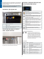
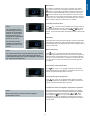
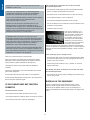
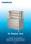
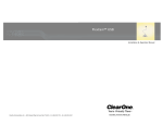
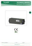
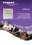
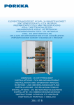
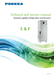
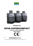
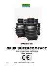
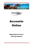
Installation and operation manual
Display Line Marine
Rev. 201411
Check the product as soon as you receive it. If you notice that
it has suffered from damages during transportation, you must
indicate this in the delivery documents and tell about the matter
to the carrier off the retailer.
IT IS VERY IMPORTANT TO READ THESE INSTALLATION
AND OPERATING INSTRUCTIONS CAREFULLY BEFORE
YOU START USING THE EQUIPMENT FOR THE FIRST
TIME.
The manufacturer’s guarantee does not cover damages
caused by transportation!
ALSO, PLEASE KEEP THESE INSTRUCTIONS IN A SAFE
PLACE FOR FUTURE REFERANCE OR USE BY ANOTHER
OPERATOR.
INSTALLATION AND INTRODUCTION
BY FOLLOWING THESE INSTRUCTIONS YOU CAN
IMPROVE THE PRODUCTS PERFORMANCE AND REDUCE
UNNESSARY REPAIR COSTS. PLEASE NOTE IT IS
IMPORTANT TO HAVE YOUR EQUIPMENT REGULARLY
MAINTAINED BY A PROFESSIONAL ENGINEER.
Unpack the counter as close to the installation place as
possible.
Remove the protective films on outer surfaces of the counter.
YOU WILL FIND THE TERMS OF GUARANTEE IN PAGE 8.
Sort packing material and dispose off according to local
legislation requirements.
Avoid placing the counter in direct sunlight or close to any
equipment radiating heat, such as cookers and radiators.
CONTENTS
RECEIPT
3
INSTALLATION AND INTRODUCTION
3
COUPLERS OF THE COOLING UNIT
4
The air forced cooling of display area - ON/OFF FUNCTION 4
OPERATION: COMBINED CONTROLLER AND DIGITAL
TEMPERATURE DISPLAY
4
Keyboard
4
Locking and unlocking the keys
4
Display lights
4
Main switch
5
To modify the temperature
5
Defrosting
5
Manual defrosting
5
To check the lowest temperature
5
To check the highest temperature
5
To delete the lowest and highest temperatures registered
5
ALARM SIGNALS FOR COMBINED CONTROLLER AND
DIGITAL TEMPERATURE DISPLAY
6
High temperature alarm
6
Low temperature alarm
6
Condenser high temperature alarm
6
Condenser low temperature alarm
6
Thermostat probe failure*
6
Evaporator probe failure*
6
Condenser probe failure*
6
COOLING UNIT
7
Removal of the unit for cleaning or servicing
7
Operators / user’s responsibility
7
DOOR
7
GOOD TO KNOW
7
CLEANING AND MAINTENANCE
7
IF THE CABINET DOES NOT FUNCTION CORRECTLY
8
The machine does not start
8
The counter does not become cool or does not reach
8
the wanted temperature
8
If the machinery gives a strange sound
8
The display area does not become cool or does not reach
the wanted temperature
8
DISPOSAL OF THE EQUIPMENT
8
GUARANTEE
9
NOTES
10
The ambient temperature must not exceed +25°C or fall below
+5°C.
Ensure the counter is horizontal.
If necessary use spirit level. The
legs are adjustable and accept
8 mm deck fixing bolts (height
adjustable -5mm to +65 mm).
All legs must touch the floor with
even weight loading per leg.
Uneven floor can distort the
frame of the counter and cause
height differences between units.
Clean the counter carefully before usage using a mild
detergent.
Do not use scouring powder, wire wool or chlorine i.e.
bleach type cleaners.
When counter is delivered and if temperature is cold,
condensation may form on the exterior surface.
Do not connect power until unit is dry and at room
temperature!
The unit should be connected to an earthed socket or
isolator with 230V/50, 230V/60Hz or 115V/60Hz supply, it
should be protected with a fuse of 10 amp rating.
Power supply (AC) and voltage at the operating point
must comply with the details on the type plate.
It is extremely important to keep foods with high acidity
such as pickles and salad dressings in air tight containers.
Highly acid foods will corrode the evaporator resulting in
expensive repair work which will not be covered by
warranty!
Ensure there is free air movement beneath the counter.
The condensation water is re-evaporated below the counter.
3
ENGLISH
RECEIPT
THESE INSTRUCTIONS ARE FOR REFRIGERATED
DISPLAY COUNTERS (DLM) FOR MARINE APPLICATIONS.
ENGLISH
OPERATION: COMBINED CONTROLLER AND
DIGITAL TEMPERATURE DISPLAY
The product must not be used outdoors or be subjected to
excessive amounts of sprayed water, especially near the
temperature display!
Keyboard
Display Line cold counters are designed and tested for
selling and storing of pre-cooled products.
COUPLERS OF THE COOLING UNIT
2.
1.
SWITCH FUNCTION
Light switch (Note! Counters with light only)
4.
The manual defrosting starts when you push the
key for 3 seconds.
The key to display and adjust the set point. In the
programming mode the adjusting function is quitted
by this key. By pressing the key for 3 seconds the
set point can be modified.
The key shows the highest thermostat value
registered. In the programming mode you navigate
inside the program or it is used to raise the selected
value.
The key shows the lowest thermostat value
registered. In the programming mode you navigate
inside the program or it is used to lower the
selected value.
Power switch (Note! The power operation light
remains illuminated even when power is switched
off).
Main power switch (Note! Only in freezers,
switch off the heat resistance of the door frame
also).
3.
1.
Socket for the electric wire
2.
Socket for light
3.
Combined controller and digital temperature display
4.
Light switch (counters with light only)
THE AIR FORCED COOLING OF DISPLAY
AREA - ON/OFF FUNCTION
Locking and unlocking the keys
The key-lock prevents unintended use of
the keys. The lock is switched on and off by
holding the keys down at the same time for
3 seconds. The display momentarily shows
letters “PoF”. With key-lock on you can still
check the lowest and highest temperature
registered. The light switch function can still
be used when keypad is locked. Pon” means
that the keys are not locked.
+
Display lights
The air forced cooling of display area shelves can be turned off
by a slide even if counter and basin is switched on.
LIGHT
MODE
OFF
On
Flashing
On
Flashing
The equipment is on standby mode.
Set temperature is displayed and can
be changed.
Compressor is running.
Time delay to protect compressor after
start-up
On
The fan of the evaporator is on.
On
Defrosting of the evaporator is on.
Flashing
On
4
FUNCTION
Drying of the evaporator is on.
ALARM, see alarms on page 5.
The cabinet is switched on and off by using the main switch
. When you move to the standby mode the code “OFF” is
displayed. In the standby mode all the control functions are off.
The freezer models additionally have a separate main switch
that also switches off the heat resistance of the door frame.
If the product is connected to the monitoring system it does not
receive control or alarm data from the monitoring unit. The light
switch functions when the instrument is on standby.
To modify the temperature
Note!
Push
key 3 seconds and the temperature set point flash on
the display. Modify the value by pushing
or
key within
15 seconds. Save the new value by pushing
key again or
wait for 15 seconds after which the display returns to the normal
mode.
The temperature of the
lower storage area of the
cabinet can be changed
from +4° to +12°C, when
the temperature in the
display area compartment
will be 6 ° to +15 °C.
Defrosting
The evaporator is defrosted automatically. During the defrosting
period the defrosting LED and temperature in the beginning of
the defrosting period are displayed. After that the display returns
to the normal mode.
The top shelve of the
display area when fitted
with three shelves is not
chilled.
Note!
Manual defrosting
The manual defrosting resets the defrosting time counter
so that by means of the manual defrosting period the
regular defrosting periods can be scheduled to take place
e.g. outside the peak periods.
Push
key for 3 seconds when the manual defrosting will
start. After manual defrost the cabinet will continue to defrost at
regular intervals. Manual defrosting is recommended if there is
a lot of ice on the evaporator, i.e. if the door has been left open
for a long time or if warm uncovered food has been placed in
the cabinet.
To check the lowest temperature
Push
key. Code “Lo” is displayed after which the lowest
registered temperature is displayed. The display returns to the
normal mode automatically after 5 seconds.
To check the highest temperature
Push
key. Code “Hi” is displayed after which the highest
registered temperature is displayed. The display returns to the
normal mode automatically after 5 seconds.
To delete the lowest and highest temperatures registered
The registered lowest and highest temperatures are deleted
separately. Get the lowest and highest temperature registered
on the display by pushing the arrow key
or
. Push
key for 3 seconds until the code “rST”
immediately the
(reset) starts to flash on the display. Release the key and the
temperatures have been deleted and the display returns to the
normal mode.
Note!
After the first start reset the lowest and highest
temperatures stored.
5
ENGLISH
Main switch
ENGLISH
ALARM SIGNALS FOR COMBINED
CONTROLLER AND DIGITAL TEMPERATURE
DISPLAY
Reset the alarm signal by pushing
CODE
REASON
“HA”
High temperature alarm
The temperature inside the cabinet has exceeded the
set alarm temperature. The alarm can be instigated
by sudden icing of the evaporator. Initiate manual
defrosting (see instructions on page 4). Ensure the
cabinet has not been loaded with warm products.
Check that a door has not been left open.Check if
product is blocking air circulation within the cabinet.
“LA”
Low temperature alarm
The temperature inside the cabinet has fallen below
the set value. Ensure that the products put into the
cabinet are not too cold.
key.
The temperature alarm is reset automatically
after the interior of the cabinet returns to set
temperature range. If this does not happen, move
the products to another cabinet and contact your
service provider.
“HA2”
Condenser high temperature alarm
The condenser / filter needs to be cleaned. Switch
the cabinet to standby mode, remove cover and
clean the filter by washing and / or using a soft brush
and vacuum cleaner. Remove dirt and debris from
the condenser face. Check also that air circulation
to the condenser is not blocked or that the ambient
temperature is not too high. If the alarm still does not
stop, remove products to another cabinet and contact
you service provider.
“LA2”
Condenser low temperature alarm
“P1”
Thermostat probe failure*
“P2”
Evaporator probe failure*
“P3”
Condenser probe failure*
*Note! The counter operates on its standby
system and will hold normal temperature, but
reset the alarm signal and immediately contact
your service provider.
6
Gasket is pull out, push in type
making change or cleaning a simple
non-technical operation.
Removal of the unit for cleaning or servicing
Switch off cabinet by pressing
standby button and remove
socket.
Remove the grating (1). Lift it
straight upwards and draw the
lower edge outwards when
the grating will come off.
Switch off power supply by
removing socket. Also remove
the socket for shelf cooling
and for light (2).
Loosen 2 screws on the lower
edge of the unit (3).
GOOD TO KNOW
Pull the cooling unit out.
Replace by reversing
procedure.
1
3
Operators / user’s responsibility
Clean the condenser filter on
the cooling unit (4) two times
a month or when necessary.
2
Remove the filter and rinse
under running water.
1. Bottom plates of the bottle basin are adjustable.
Shake off excess water and
replace filter.
2. Shelve LED illumination and the well LED light are
supplied as standard in the display area compartment.
3. Air duct channels on the ends of compartment’s shelves must
not be covered!
Clean the finned condenser on the unit (5) once a month using
a soft brush and / or vacuum cleaner. Take care not to
damage fins.
CLEANING AND MAINTENANCE
If the counter is situated in a very dusty environment, i.e.
bakery, it has to be cleaned more often.
Clean spillages immediately.
The cooling unit should be removed and serviced by
a professional company 1-2 times per year.
Ensure effective operation of the equipment and the quality of
the stored products by defrosting and cleaning the equipment
once a month at least.
DOOR
Remove all food and store it in a back-up store.
Switch off the unit from the main electrical power switch and
take off the electric wire from the wall socket.
Doors are equipped with marine handle complete with lock,
magnetic gasket and heavy-duty hinges.
Remove shelves and GN rails as well as drawers and runners.
Wash the stainless steel surfaces of the equipment by a mild
detergent mixed with water *, e.g. dishwasher detergent
or other suitable detergent. Use a cloth or a paper towel to
prevent scratching.
7
ENGLISH
COOLING UNIT
ENGLISH
The counter does not become cool or does not reach
the wanted temperature
RINSE WITH A DAMP CLOTH, DRY AND ALLOW THE
CABINET TO DRY OUT.
• check that the thermostat has been correctly adjusted (SET
button, to modify the temperature set points).
* DO NOT USE DETERGENTS OR DESINFECTANTS
CONTAINING CHLORINE, SOLVENTS, SCRUBBING
PRODUCTS, A KNIFE OR OTHER SHARP TOOLS.
• the defrost is not on (the defrost-LED is on the control unit).
DO NOT USE RUNNING WATER TO WASH THE CABINET,
THE COOLING UNIT OR THE CABINET WITH
THE COOLING UNIT IN PLACE.
• air circulation inside the unit is not blocked
REFER TO THE PRODUCT DESCRIPTION OF THE
DESINFECTANT TO SEE WHICH MATERIALS IT IS
SUITABLE FOR. DO NOT LET IT SPLASH ON SENSITIVE
PARTS, SUCH AS THERMOSTAT REGULATOR OR DOOR
HINGES. DRY THE EQUIPMENT AFTER THE
DESINFECTION AND LET IT VENTILATE.
• the air circulation for the condenser is free and the filter of the
condenser is not blocked
• check that the ambient temperature is not too high.
• evaporator has not frozen:
This can be caused by e.g. a
door that has been left ajar or
high air humidity. Check inside
the unit if there is ice in the
air circulation openings of the
rear edge of the cold machine
cassette. If you notice ice or if
you suspect that the evaporator
has frozen, start “manual
defrost” according to the instructions. Repeat manual defrosts
until the evaporator is completely free of ice. In case the product
still does not reach the temperature needed, contact a service
company.
CLEANERS WITH ALCOHOL OR WITH ALCOHOL
DERIVATIVES AND OTHER CLEANING MATERIALS AND
CLEANING AGENTS WHICH ARE NOT RECOMMENDED
FOR USE WITH ACRYLIC MATERIALS, SHOULD NOT BE
USED WHEN CLEANING THE ACRYLIC PANELS,
ESPECIALLY THE FRONT PANELS (HATCHES).
USE WATER WITH MILD FOOD SAFE DETERGENT AND
DRY WITH A SOFT CLOTH OR CHAMOIS LEATHER, DO
NOT USE ABRASIVE MATERIALS OR MICRO-CLOTHS AS
THESE WILL SCRATCH THE SURFACE.
If the machinery gives a strange sound
Clean the condenser and/or condenser filter.
• check that the feet of the counter are adjusted properly. Make
sure that the cabinet does not rock when pushed from one or
another of the front corners.
Clean the counter door gasket using a mild water soluble
detergent and check the condition of the gasket. A silicone
spray makes the gaskets flexible and dirt-rejecting.
• ensure that goods inside the unit, e.g. bottles, do not clink
against each other.
Lubricate the drawer runners with lubricant suitable for
foodstuff.
Cleaning in dishwasher is not recommendable for the loose
parts of the equipment.
The display area does not become cool or does not reach
the wanted temperature
Put back all removed parts and switch on the equipment.
• check that the air forced cooling of display area shelves is not
turned off by a slide.
Ensure that the temperature has become to the normal level
before using the equipment again.
DISPOSAL OF THE EQUIPMENT
IF THE CABINET DOES NOT FUNCTION
CORRECTLY
Once the equipment becomes redundant it may not be
disposed of with normal waste because the equipment is
governed by the WEEE directive. It has to be disposed of
following the WEEE act which became effective on August 13th
2005.
The machine does not start
• check that the main switch has been turned to ON.
• check that the electric cable has been connected to a socket.
• check that the fuse of the socket is undamaged.
8
ENGLISH
GUARANTEE
Check the guarantee period at your merchandiser.
The guarantee does not cover faults caused by
• transportation
• overloading or users negligence
• negligence due to not reading manuals, proper care and
maintenance
• changes in current (max ± 10% allowed) caused for example
by lightning etc.
• modifications or repairs performed by an unauthorized service
agent
• use of parts not supplied and approved by the manufacturer
The guarantee does not cover
• incidental scratches/marks or other minor faults caused when
unpacking or during installation that does not effect operation
or performance of the equipment
THE MANUFACTURER OR HIS SELLING AGENT IS NOT
AT ANY TIME, OR UNDER ANY CIRCUMSTANCES LIABLE
FOR FOOD LOSS HOWSOEVER IT OCCURS. THE OWNER /
USER SHOULD ENSURE THE CONTENTS ARE INSURED AT
ALL TIMES.
ALL GOOD ARE SUPPLIED UNDER OUR TERMS AND
CONDITIONS OF SALE A COPY OF WHICH MAY BE
OBTAINED UPON REQUEST.
9
NOTES
10
NOTES
11
Porkka Finland Oy is an internationally
recognised designer and manufacturer of
Marine Refrigeration Equipment
Porkka Finland Oy is an internationally recognised designer and manufacturer of
Refrigeration and Food Storage/Display Equipment. The range incorporates Chilled,
Frozen and Heated options. Major clients include commercial kitchens, restaurants, fast
food outlets, hotels, industrial canteens, hospitals, laboratories and retailers throughout
the World.
Our main markets outside of Finland include Scandinavia, United Kingdom, Germany,
Switzerland, Holland, Belgium, Russia and the Baltic regions. 80% of the companies’
turnover is derived from foreign transactions and exports. On going and adaptive
development by numerous foreign subsidiaries and representatives ensures our
continued growth.
Porkka’s success is based on decades of experience, customer focused design and
continuous product development.
Porkka Finland Oy is part of the Huurre Group. Porkka and Huurre brands are well known
for their quality and reliability throughout the world.
marked products. The manufacturer through continuous research and development
reserves the right to change technical specification and design without notice.
Porkka Finland Oy reserves the right to make any changes without prior notice.
Porkka Finland Oy
Porkka Scandinavia AB
Porkka Norge AS
Porkka (U.K.) Limited
Soisalmentie 3
FI-15860 Hollola, Finland
Tel. +358 20 5555 12
Fax +358 20 5555 497
e-mail: [email protected]
www.porkka.com
Industrigatan 21
S-61933 Trosa, Sverige
Tel. +46 156 348 40
Fax +46 156 167 50
e-post: [email protected]
www.porkka.se
Lensmannslia 30
N-1386 Asker, Norge
Tel. +47 66 98 77 77
Fax +47 66 98 77 88
e-post: [email protected]
www.porkka.no
29B Greenhill Crescent
Watford Business Park, Watford
Hertfordshire, WD18 8YB, UK
Tel. +44 1923 23 36 75
Fax +44 1923 80 57 17
e-mail: [email protected]
www.porkka.co.uk