1
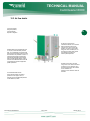
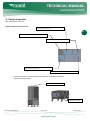
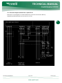
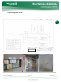
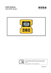
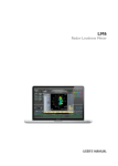
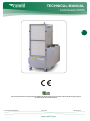
TECHNICAL MANUAL CamCleaner 6000 1 There are no general rules for recycling of used filters. Different rules excists on local level in all countries. Please contact the recycling company in your district and ask how to handle used filters. CamCleaner 6000/Manual, Rev. 6012 www.camfilfarr.com January 2013 TECHNICAL MANUAL CamCleaner 6000 1. INDEX 2 2. PURPOSE / CONTENTS 3 3. VERSION HISTORY 3 4. IDENTIFICATION PLATE 3 5. GUARANTEES AND UNDERTAKINGS 3 6. PREFACE 4 7. TECHNICAL SPECIFICATIONS 4 8. USE 5 8.1. WALL AND CEILING MOUNTING 6 9. SAFETY INSTRUCTIONS 6,7 10. DESIGN 8,9 2 10.1. CONSTITUENT STANDARD COMPONENTS 10 11. TRANSPORT AND UNPACKAGINS 10 10.2. AIR FLOW DETAILS 11 12. TAKING INTO OPERATION 12 12.1. POSITIONING 14 12.2. SYSTEM INTEGRATION 14 12.3,4,5.6 ELECTRICAL CONNECTION 14,15,16 13. MEASSURING POINT FOR PA 17 14. CAMCLEANER 6000 AND THE ENVIRONMENT 18 14.1. CAMCLEANER 6000 FILTERS AND THE ENVIRONMENT 18 15. MAINTENANCE 19 16. INSTRUCTIONS FOR REPLACING CAMCLEANER 6000 FILTERS 19 16.1. FILTER REPLACEMENT 19,20 17. IP CLASSIFICATION 21 18. EU PROVISIONS GOVERNING THE PRODUCT 21 CamCleaner 6000/Manual, Rev. 6012 www.camfilfarr.com January 2013 TECHNICAL MANUAL CamCleaner 6000 1. Purpose This user manual is part of the documentation that must be available under appendix 5 of the machine directive. The purpose of the manual is to give details of the design of the CamCleaner 6000 and how it works. New users must be able to work safely with the CamCleaner 6000. 3 2. Contents This user manual gives details of the CamCleaner 6000 only and must not be used for any other machine. Besides short explanations of what the machine is used for, the first few sections also give some technical specifications. After these, there are illustrated texts about the various parts that make up the CamCleaner 6000. The user manual also includes details of safety procedures associated with the use of the machine. 3. Version history Version 6012 Date See approval Signature Initial Altered Version 4. Identification plate All CamCleaner 6000 type machines have this plate on their fan box. 5. Guarantees and undertakings The guarantee relates to full functionality as per the details in this user manual and covers errors in software and hardware for a period of one year from the delivery date. Should the equipment develop a fault, please contact your distributor. Distributor of CamCleaner 6000: CAMFIL Industrigatan 3 SE-619 33 TROSA Tel: +46 (0)156 537 00 Web: www.camfil.com CamCleaner 6000/Manual, Rev. 6012 www.camfilfarr.com January 2013 TECHNICAL MANUAL CamCleaner 6000 6. Preface Thank you for buying an air purifier from Camfil. We hope that you will be delighted with your CamCleaner 6000. 4 Important! Before using your CamCleaner 6000 air purifier, it is important that you, as the user: read this user manual; read the fan instructions; and, follow the safety instructions in both documents. 7. Technical specifications External dimensions, vertical model Height: 1968 mm Width: 798 mm Depth: 820 mm External dimensions, horizontal model Height: 1359 mm Width: 1262 mm Depth, 829 mm Weight: 130.5 kg (including new filters) Filter weight: 23 kg (4 x Ecopleat 50 mm and 2 x EPA 11) CamCleaner 6000/Manual, Rev. 6012 www.camfilfarr.com January 2013 TECHNICAL MANUAL CamCleaner 6000 Fan specifications NB! There are 2 different motor options for the fan. If unsure, fan type can be identified from the rating plate on the machine. 5 3-phase EC fan Voltage: 3~ V AC, 380/480 V Frequency: 50/60 Hz, IP 54 Max. power: 1.95 kW Max. current: 2.6 – 3.3 A Speed: 2,300 rpm min. -1 Noise level: 35 dbA – 87 dbA Operating temperature: -25˚C – 60˚C 1-phase EC fan Voltage: 1~, 200 – 277 V Frequency: 50/60 Hz, IP 54 Max. power: 1.25 kW Max. current: 4.5 – 6.2 A Speed: 1,950 rpm min. -1 Noise level: 35 dbA – 85 dbA Operating temperature: -25˚C – 60˚C Air flow, CamCleaner 6000 1,000m3/h – 7,500m3/h (max. mode with unused filters). The capacity is 6,000m3/h throughout the entire filter’s service life. 8. Use The CamCleaner 6000 is used to clean air by mechanically filtering it through highly efficient filters. Available as vertical and horizontal models, there are two standard versions of the CamCleaner 6000. They both have lockable wheels and are mobile. CamCleaner 6000/Manual, Rev. 6012 www.camfilfarr.com January 2013 TECHNICAL MANUAL CamCleaner 6000 8.1. Wall and ceiling mounting If the CamCleaner 6000 is to be mounted in a ceiling or a wall, the following points must be borne in mind: 1.Ceiling mounting – the unit must be so mounted that there is no risk of trucks (and similar) colliding with it. 2.The ceiling or wall must be able to take a load of 400 kg. 6 3.Only fixed mounting is permitted. 4.Mounting devices must be able to take a load of at least 400 kg. 5.Position the CamCleaner 6000 on a stable, firm and flat surface or on a beam (applies to vertical models). Alternatively, mount it on a wall. Horizontal models must be mounted horizontally and vertical models must be mounted vertically. 9. Safety instructions Read the user manual and follow the instructions given therein. For installation, servicing, maintenance or filter replacement, the machine's power supply must be disconnected. NB! Pull out the electrical connector! The machine is not to be regarded as de-energised until 5 minutes after disconnection from the power supply. Rotating parts do not stop immediately once power has been cut or the machine has been switched off. Allow 5 minutes to elapse before handling the cabinet. 1. In its standard version, the CamCleaner 6000 must only be used for handling dry non-explosive materials. If the air purifier is used for purposes other than those set out in the user manual, or is handled otherwise than set out therein, Camfil Svenska AB can accept no liability whatsoever for the consequences of said use/handling. 2. NB! Fixed installation may only be carried out by a professional who has appropriate qualifications for the assignment and who takes responsibility for the installation. 3. The machine must not be used in ATEX classified areas or where, at any time, there may be explosive gases. 4. Electrical connection may only be carried out by an appropriately qualified electrician. Wall outlets must also be installed by an appropriately qualified electrician. 5. Accessories, filters, spare parts, etc. used with the CamCleaner 6000 must be approved by Camfil Svenska AB. Guarantee undertakings cease to apply if the foregoing is not respected. Please contact Camfil Svenska AB for the correct accessories. CamCleaner 6000/Manual, Rev. 6012 www.camfilfarr.com January 2013 6 TECHNICAL MANUAL CamCleaner 6000 6. Do not cover inlets or outlets. 7. Inserting objects through inlets or outlets is forbidden. 8. The wheels must be locked throughout operation. 9. The CamCleaner 6000 must not be used in environments where burning/smouldering objects can get into the machine. 7 7 10. The CamCleaner 6000 must be used indoors only. 11. The CamCleaner 6000 must be used in the 5˚C – 60˚C temperature range only. 12. The CamCleaner 6000 must not be drenched with water. The highest permitted humidity is 85%. 13. The CamCleaner 6000 must not be used for point extraction or dust separation. It must also not be used in environments where dust explosions may occur. 14. Your CamCleaner 6000 is equipped with “automatic start”. This means that, on power restoration after a power disruption, the fan automatically returns to its speed before the disruption. 15. Follow the filter handling and replacement instructions very carefully. Incorrect handling can damage the filter medium. In turn, this can mean that the promised filter class will not be achieved. 16. Take great care when handling used filters. Incorrect handling can result in ill health or sickness. Follow the instructions for filter replacement. 17. The CamCleaner 6000’s filter must always be removed before the machine is transported on a trailer. 18. The machine must not be changed from horizontal to vertical or vice versa. The guarantee is voided if the screws that hold the upper section to the lower section are undone. 19. When replacing filters, remember that the protective grilles are heavy – your feet are vulnerable! When replacing filters with the machine raised from the floor, it is recommended that the grilles, before they are detached, should be secured with wire. 20. Be aware of that the CamCleaner 6000 have a high noise level at high speed and protection for the ear must be used. CamCleaner 6000/Manual, Rev. 6012 www.camfilfarr.com January 2013 TECHNICAL MANUAL CamCleaner 6000 10. Design The CamCleaner 6000 is a self-standing two-section design. One of the sections (the filter section) houses the filters. The other section (the fan section) houses the fan and all the electrical and control apparatus. The protective grilles in front of the filters form a third part. They may be removed when replacing filters. The machine is entirely constructed of lacquered steel plates. Thus, it is environment friendly and readily recyclable. Filter cabinet Fan cabinet CamCleaner 6000/Manual, Rev. 6012 www.camfilfarr.com January 2013 8 TECHNICAL MANUAL CamCleaner 6000 Protective grille 9 9 Filter frame CamCleaner 6000/Manual, Rev. 6012 www.camfilfarr.com January 2013 TECHNICAL MANUAL CamCleaner 6000 10.1. Constituent standard components In its standard version, the air purifier is supplied with the following components: One CamCleaner 6000 unit with 4 circular outlet pipes (Ø 315 mm). These have rubber gaskets and can be connected to circular ducts. Two protective grilles (for filter protection) with 8 grille locks. Two filter frames. One machine spanner for the junction box’s hatch. Filters for the chosen purpose. Filter replacement warning light and associated pressure sensors. User manual. Fan instructions (from the fan supplier). If anything is missing, or if you require further information about accessories, please contact Camfil. 11. Transport and unpackaging When the CamCleaner 6000 is to be installed, remove the packaging carefully. If sharp objects are used for unpackaging, take care of the machine’s cables and lacquer finish. Vertical and horizontal models alike, the CamCleaner 6000 is supplied with four wheels and can thus be easily moved to the point of use. Take especial care when handling the filters. See the filter replacement section. Check that the product has not been damaged during transport. Report any transport damage to the carrier. Check also that the delivery is complete. CamCleaner 6000/Manual, Rev. 6012 www.camfilfarr.com January 2013 10 TECHNICAL MANUAL CamCleaner 6000 10.2. Air flow details 1. The air first passes through two prefilters, most often pleated Ecopleats or bag filters 11 4. The only moving part in the CamCleaner is the fan. This is under the filters and creates strong and even underpressure in the air column after the filters. Our EC fans consume little 11 energy and can be controlled (even via the internet) for optimal needs-specific air purification and indication of necessary filter replacement. 2. Behind these, there is the HEPA filter. This is a unique, environment-friendly “absolute filter”. It is so efficient that air must pass three times through the ventilation system to achieve the same level of air purification as it does in a single circulation through the CamCleaner. The extremely large filter surface increases both service life and filter efficiency. Further increases of the HEPA/EPA filter’s service life can be achieved by careful management of prefilter replacement. 2 5. Outlets can be made on two sides using round 315 mm standard connectors or silencers on one or both sides. Thus, the CamCleaner 6000 can be connected to most ventilation duct dimensions or even allowed to stand and recirculate. 1 3 4 5 3. All CamCleaner 6000 models have at least two intakes. This makes it possible to mix and purify air from, for example, two areas at different temperatures or with different air qualities CamCleaner 6000/Manual, Rev. 6012 www.camfilfarr.com January 2013 TECHNICAL MANUAL CamCleaner 6000 12. Taking into operation First, read the entire user manual. Schematic diagram of the junction box. Low-voltage connection box 12 3. Rotary control for desired operating mode 4. Pressure sensor for filter replacement High-voltage connection box 4. Pressure sensor for constant flow (accessory) 1. Connect the air purifier to the electrical outlet. Ensure that there is nothing obstructing the air outlets/inlets (see figure below). Filter replacement warning light The junction box´s hatch CamCleaner 6000/Manual, Rev. 6012 www.camfilfarr.com January 2013 TECHNICAL MANUAL CamCleaner 6000 2. Using the supplied machine spanner, remove the junction box’s hatch (see figure above). 3. Turn the rotary control on the potentiometer box clockwise until a click is heard. The fan is now on. A couple of seconds will elapse before it begins to move. Next, using the rotary control, select the desired speed. For potentiometer location, see “Schematic diagram of the junction box” (above). 13 To switch the fan off, turn the potentiometer anticlockwise until a click is heard. 4. If the filter replacement setting must be changed, use a screwdriver to remove the plastic lid (see pictures below). 5. Turning the knob in the centre of the pressure sensor, turn to the Camfil recommended final pressure drop. For sensor location, see also the “Schematic diagram of the junction box” (above). When it is time to replace filters, the warning light flashes. Filters should be replaced as soon as possible. Your CamCleaner 6000 is equipped with “automatic start”. This means that, on the restoration of power after a power disruption, the air purifier automatically returns to the speed at which it was set before the disruption. The user/installation engineer must bear this in mind during use, servicing or the carrying out of fixed installation. CamCleaner 6000/Manual, Rev. 6012 www.camfilfarr.com January 2013 TECHNICAL MANUAL CamCleaner 6000 12.1. Positioning The CamCleaner 6000 must always be positioned and used indoors only. When using the air purifier, lock its wheels. Air outlets and intakes must not be obstructed during use. Before it is taken into operation, ensure that there is sufficient space (50 cm) around the machine. 14 12.2. System integration When connecting the CamCleaner 6000 to the ventilation system, the load on the CamCleaner 6000 must not exceed a total weight of 25 kg (of which a maximum of 10 kg on the intake side). Systems heavier than this must be secured to support their own weight. 12.3. Electrical connection Electrical connection must be carried out by an appropriately qualified electrician. All routing of cables, etc. must be carried out in accordance with the relevant regulations. The CamCleaner 6000 is factory supplied ready for plugging in. Any intervention in the machine’s internal electrical systems may only be carried out by appropriately qualified persons using Camfil Svenska AB supplied equipment. The CamCleaner 6000 may only be connected to the network voltage that is stated on the machine plate. CamCleaner 6000/Manual, Rev. 6012 www.camfilfarr.com January 2013 TECHNICAL MANUAL CamCleaner 6000 12.4. Connection diagram, terminal block, 3-phase EC fan Below, there is a circuit diagram for connections between fan, junction box and accessories. NB! Only appropriately qualified electricians may carry out work on or in this. 15 CamCleaner 6000/Manual, Rev. 6012 www.camfilfarr.com January 2013 TECHNICAL MANUAL CamCleaner 6000 12.5. Connection diagram, terminal block, 1-phase EC fan Below, there is a circuit diagram for connections between fan, junction box and accessories. NB! Only appropriately qualified electricians may carry out work on or in this. 16 CamCleaner 6000/Manual, Rev. 6012 www.camfilfarr.com January 2013 TECHNICAL MANUAL CamCleaner 6000 13. Measuring points for Pa. 17 CamCleaner 6000/Manual, Rev. 6012 www.camfilfarr.com January 2013 TECHNICAL MANUAL CamCleaner 6000 14. CamCleaner 6000 and the environment The CamCleaner 6000 air purifier is made from lead-free components. Because the CamCleaner 6000 can be recycled, used models must always be sent to a recycling station for correct recycling and/or disposal of parts and components. 19 18 14.1. CamCleaner 6000 filters and the environment Note that filters must not be disposed of along with ordinary household waste. Scrapped filters must always be correctly taken care of and handled safely. Recycling or disposal must always be carried out at an approved waste facility. If you have any questions about this, please contact your local authority or distributor for advice on correct care. CamCleaner 6000/Manual, Rev. 6012 www.camfilfarr.com January 2013 TECHNICAL MANUAL CamCleaner 6000 15. Maintenance If necessary, the CamCleaner 6000 can be cleaned using a mild cleaning agent. Before cleaning, always switch off the machine and pull out the electrical connector! 19 Remove the protective grilles before you clean them. NB! Do not touch the filter surface. 16. Instructions for replacing CamCleaner 6000 filters WARNING! When handling used filters, personal protective equipment such as protective gloves and masks must be used. To choose the correct type of respiratory protection, consult either the safety representative/officer at the workplace or the manufacturer of the respiratory protection. Used filters may contain harmful substances and particles. With incorrect handling, these can escape to the environment and present risks of sickness and ill health. Filters should be replaced on a continuous basis. As regards frequency of filter replacement, see Camfil Svenska AB’s or the manufacturer’s recommendations. 16.1. Filter replacement Always use protective gloves and respiratory protection when handling used filters! Risk of ill health and sickness. 1. Switch off the CamCleaner 6000 by turning the rotary control until a click is heard. 2. When the CamCleaner 6000 has been switched off and the fan has stopped, pull out the electrical connector. 3. Undo the four grille locks of one of the grilles. NB! Hold the grille firmly. Alternatively, secure it during removal. It is heavy. 4. Lift out the grille and put it to one side. 5. Grip the upper edge of the filter frame (which has the 2 outer filters) and lift it to one side. 6. Dismount both outer filters and put them in a bag. 7. Grip the upper edge of the inner filter and swing out the upper edge so that the filter’s top face is entirely outside the machine’s edge. 8. Lift the filter carefully out. Scrapped filters must be taken care of as per the previously explained instructions. 9. Take a new inner filter out of its box. NB! Do not touch the filter’s surface. Hold the frame only! 10. Bottom first and angled slightly outwards at its upper edge, lift the new filter into the cabinet. CamCleaner 6000/Manual, Rev. 6012 www.camfilfarr.com January 2013 TECHNICAL MANUAL CamCleaner 6000 11. Support the filter on its lower edge in the cabinet and then carefully push in the top. The support pads will offer a little resistance. However, this is so that the filter is later held in place while the filter frame and grille are mounted. 12. Check that, at both the upper edge and at the lower edge, the filter has come up against the frame. 13. Release the filter and verify that it does not topple out again. When you have ensured that the filter stays in place, fetch the filter frame. 20 14. Put the filter frame in place and open the box with the new outer filters. 15. First mount the lower filter in the filter frame and then mount the other filter. 16. Put the frame back in place and do up the grille locks. Take great care here not to let go of the grille – risk of foot injuries. Do up the grille screws firmly. 17. Repeat steps 1 to 14 for the other side. 18. Reconnect the electrical connector. Your CamCleaner 6000 is equipped with “automatic start”. This means that, after a power disruption, it automatically starts up and returns to its speed before the disruption. CamCleaner 6000/Manual, Rev. 6012 www.camfilfarr.com January 2013 TECHNICAL MANUAL CamCleaner 6000 17. IP classification The CamCleaner 6000 is supplied with an IP 54 classification. 21 The IP code is defined as per international standard IEC 60529. 21 In accordance with the IP 54 standard (ingress protection), the product tolerates dust and water splashes. It provides safety for users in various work environments that are damp or dusty. IP classifications define how much dust and water a product tolerates while maintaining full functionality and safety. Important information In accordance with the casing’s stated protection classification, the machine must not be placed in water or exposed to liquid chemicals. Similarly, the machine must not be placed in extremely high or low temperatures. The guarantee does not cover problems arising through carelessness/negligence. Remember that the classification covers the machine only and not the filters. For information about filters, contact the filter supplier. 18. EU provisions governing the product This product complies with EU standards as per the “machine directive” (2006/42/EC), the “low voltage” directive (2006/95/EC) and the “EMC directive” (2004/108/EC). Note that correct observance of the installation and safety instructions is a precondition for the compliance of all the operating properties. For more details of technical specifications, the standards that have been complied with and Camfil’s patents, please contact Camfil Svenska AB. CamCleaner 6000/Manual, Rev. 6012 www.camfilfarr.com January 2013 TECHNICAL MANUAL CamCleaner 6000 CAMFIL – the world’s largest and leading manufacturer of filters and clean air solutions 22 There is a good chance that, at this very moment, you are breathing clean air that has passed through a filter manufactured by us. Our products can be found everywhere from offices, clean rooms for sensitive electronics production and mines to factories, hospitals and nuclear power stations. Camfil is a global company with 29 subsidiaries, 23 production plants and an extensive network of agents in Europe, the Americas and the Asia-Pacific region. CamCleaner CamCleaner is synonymous with high efficiency purification, energy savings and almost silent operation. Unlike all other air purifiers on the market, our HEPA filters offer a degree of purification that can eliminate the tiniest and most difficult to remove particles. CamCleaner is also entirely unique in that it can suck in air from two directions. This makes it possible to have different cleaning zones and thereby considerably increase the efficiency of air purification. CamCleaner 6000/Manual, Rev. 6012 www.camfilfarr.com January 2013