1
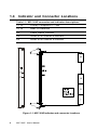
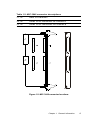
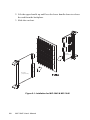
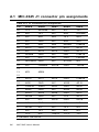
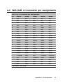
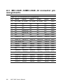
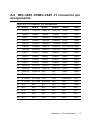
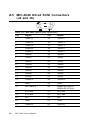
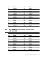
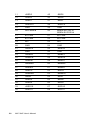
MIC-3645 6U Ultra3 Wide SCSI Interface card for CompactPCI TM Modular Industrial Computer CompactPCI TM Modular Industrial Computer Copyright Notice This document is copyrighted, 2001. All rights are reserved. The original manufacturer reserves the right to make improvements to the products described in this manual at any time without notice. No part of this manual may be reproduced, copied, translated or transmitted in any form or by any means without the prior written permission of the original manufacturer. Information provided in this manual is intended to be accurate and reliable. However, the original manufacturer assumes no responsibility for its use, nor for any infringements upon the rights of third parties which may result from its use. Acknowledgments IBM, OS/2 are trademarks of International Business Machines Corporation. Intel, Pentium, are trademarks of Intel Corporation. Windows is a registered trademark of Microsoft Corporation. Symbios is a trademark of Symbios Logic Corporation. Netware is a trademark of Novell, Inc. PICMG™, CompactPCI™ and the PICMG™, and CompactPCI™ logos are trademarks of the PCI Industrial Computers Manufacturers Group. All other product names or trademarks are properties of their respective owners. CE Notification The MIC-3645, developed by Advantech CO., LTD., has passed the CE test for environment specification when shielded cable are used for external wiring. We recommend the use of shielded cables. Part No. 2006364500 Printed in Taiwan 1st Edition August 2001 Preface and Table of Contents MIC-3645 User's Manual Product warranty Advantech warrants to you, the original purchaser, that each of its products will be free from defects in materials and workmanship for one year from the date of purchase. This warranty does not apply to any products which have been repaired or altered by persons other than repair personnel authorized by Advantech, or which have been subject to misuse, abuse, accident or improper installation. Advantech assumes no liability under the terms of this warranty as a consequence of such events. Because of Advantech’s high quality-control standards and rigorous testing, most of our customers never need to use our repair service. If an Advantech product is defective, it will be repaired or replaced at no charge during the warranty period. For out-of-warranty repairs, you will be billed according to the cost of replacement materials, service time and freight. Please consult your dealer for more details. If you think you have a defective product, follow these steps: 1. Collect all the information about the problem encountered. (For example, CPU speed, Advantech products used, other hardware and software used, etc.) Note anything abnormal and list any onscreen messages you get when the problem occurs. 2. Call your dealer and describe the problem. Please have your manual, product, and any helpful information readily available. 3. If your product is diagnosed as defective, obtain an RMA (return merchandize authorization) number from your dealer. This allows us to process your return more quickly. 4. Carefully pack the defective product, a fully-completed Repair and Replacement Order Card and a photocopy proof of purchase date (such as your sales receipt) in a shippable container. A product returned without proof of the purchase date is not eligible for warranty service. 5. Write the RMA number visibly on the outside of the package and ship it prepaid to your dealer. Preface and Table of Contents Packing List Before installing your board, ensure that the following materials have been received: • One MIC-3645 CompactPCI SCSI card • One MIC-3646 rear transition board • One utility CD-ROM disc and user's manual(PDF file) • One warranty certificate If any of these items are missing or damaged, contact your distributor or sales representative immediately. Technical Support and Sales Assistance If you have any technical questions about the MIC-3645 or any other Advantech products, please visit our support website at: • http://www.advantech.com.tw/support For more information about Advantech's products and sales information, please visit: • http://www.advantech.com MIC-3645 User's Manual Contents 1. General Information ............................................................ 1 1.1 1.2 1.3 1.4 1.5 Introduction ................................................................................. 2 Features ....................................................................................... 2 Specifications .............................................................................. 3 Indicator and Connector Locations ............................................. 4 Safety Precautions ...................................................................... 6 2. Hardware and Drivers Installation .................................... 7 2.1 Initial Inspection .......................................................................... 8 2.2 Card Installation .......................................................................... 9 2.3 Driver Installation ..................................................................... 11 2.3.1 Utility and Drivers ....................................................................... 11 A. Pin Assignments ............................................................... 13 A.1 A.2 A.3 A.4 A.5 A.6 MIC-3645 J1 connector pin assignments ................................. 14 MIC-3645 J2 connector pin assignments ................................. 15 MIC-3645 J3/MIC-3646 J2 connector pin assignments .......... 16 MIC-3645 J5/MIC-3645 J1 connector pin assignments .......... 17 MIC-3646 Ultra3 SCSI Connectors (J4 and J6) ...................... 18 MIC-3646 Ultra3 SCSI Connectors (J3 and J5) ...................... 19 Preface and Table of Contents Figures Figure 1-1: MIC-3645 indicator and connector locations ............................. 4 Figure 1-2: MIC-3646 connector locations .................................................... 5 Figure 2-1: Intallation for MIC-3645 & MIC-3646 ........................................... 8 MIC-3645 User's Manual Tables Table A-1: J1 connector pin assignments .................................................. 14 Table A-2: J2 connector pin assignments .................................................. 15 Table A-3: J3 connector pin assignments .................................................. 16 Table A-4: J5 connector pin assignments .................................................. 17 Table A-5: MIC-3646 Ultra3 SCSI connectors ............................................. 18 Table A-6: MIC-3646 Ultra3 SCSI connectors ............................................. 19 Preface and Table of Contents MIC-3645 User's Manual CHAPTER 1 General Information 1.1 Introduction The MIC-3645 is a 6U-size high-speed SCSI module for CompactPCI™ systems. It complies with PICMG 2.0 R 3.0 CompactPCI™ Specification. The MIC-3645 uses the Symbios® SYM53C1010-33, PCI to Dual Channel Ultra3 SCSI Multifunction Controller, to provide an Ultra3 wide SCSI interface. The SYM53C1010 supports a 64-bit or 32-bit, 33 MHz PCI bus and performs 16-bit, Ultra3 SCSI synchronous data transfers as fast as 160 Mbytes/s on each SCSI channel providing a total bandwidth of 320 Mbytes/s. The MIC-3645 can support cables up to 12 meters long, and up to 16 LVD or SE devices on a wide SCSI bus. On the front panel of the MIC-3645, there are three LED indicators to monitor the operations of the two Ultra3 SCSI channel as well as the power status. The rear transition board, MIC3646, provides two external connectors and two internal connectors for easy system configuration. Users can choose the more convenient connection to set up their system. The MIC-3645 supports a variety of operating systems, including DOS, Windows NT/2000/98/95/ME, Solaris and SCO UNIX. 1.2 Features • Dual SCSI channels • 64-bit or 32-bit, 33 MHz PCI bus interface • High data transfer rates up to 160 MB/s • Supports for operations for 16 separate SCSI devices • Provides two external and two internal connectors on the rear I/O transition board for easy system configuration • LED indicators for easy monitoring 2 MIC-3645 User's Manual 1.3 Specifications • Controller: Symbios® SYM53C1010-33 • Supports 16-bit Low Voltage Differential (LVD) signaling • Performs Ultra3 SCSI LVD synchronous transfers as fast as 160 MB/s Rear Transition Board (MIC-3646) • Two internal and two external SCSI connectors Mechanical and Environmental Specifications • Board size: MIC-3645: 233.35 x 160 mm (9.2" x 6.3"), 1-slot (4TE) width MIC-3646: 233.35 x 80 mm (9.2" x 3.15"), 1-slot (4TE) width • Weight: MIC-3645: 0.4 kg MIC-3646: 0.3 kg • Power consumption: +3.3 V @ 2.0 A (max.) • Operating temperature: 0 ~ 60º C (32 ~ 158º F) • Storage temperature: -20º ~ 80º C (-4 ~ 176º F) • Humidity (operating and storage): 5 ~ 95% (non-condensing) • Shock: 10 G (operating); 30 G (storage/transit) • Random vibration: 1.5 Grms Chapter 1 General Information 3 1.4 Indicator and Connector Locations Table 1-1: MIC-3645 connector and indicator descriptions J1, J2 Primary CompactPCI bus J3, J5 Rear I/O transition D2 Power status indicator D4 Ultra3 SCSI channel A indicator D5 Ultra3 SCSI channel B indicator Figure 1-1: MIC-3645 indicator and connector locations 4 MIC-3645 User's Manual Table 1-2: MIC-3646 connector descriptions J1, J2 Rear I/O transition J4, J6 Ultra3 SCSI connectors for channel A J3, J5 Ultra3 SCSI connectors for channel B Figure 1-2: MIC-3646 connector locations Chapter 1 General Information 5 1.5 Safety Precautions Follow these simple precautions to protect yourself from harm and the products from damage. 1. To avoid electric shock, always disconnect the power from your PC chassis before you work on it. Don't touch any components on the CPU card or other cards while the PC is on. 2. Always ground yourself to remove any static charge before you touch your SCSI card. Be particularly careful not to touch the chip connectors. Keep the card in its antistatic packaging when it is not installed in the PC, and place it on a static dissipative mat when you are working with it. Wear grounding wrist strap for continuous protection. 6 MIC-3645 User's Manual CHAPTER 2 Hardware and Drivers Installation 2.1 Initial Inspection We carefully inspected the MIC-3645 and MIC-3646 mechanically and electronically before shipping. It should be free of marks and scratches and in perfect working order on receipt. As users unpack the MIC-3645 and MIC-3646 , check it for signs of shipping damage (damaged box, scratches, dents, etc.). If it is damaged or fails to meet specifications, notify Advantech's service department or the local sales representative immediately. Also notify the carrier that was used to ship the product to user's location from Advantech's factory or distributor. Retain the shipping carton and packing material for inspection by the carrier. Advantech will make arrangements to repair or replace the unit after an inspection. Warning: Discharge your body's static electric charge by touching the back of the grounded chassis of the system unit (metal) before handling the board. You should avoid contact with materials that hold a static charge such as plastic, vinyl and styrofoam. Touch the board only by its edges to avoid static damage to its integrated circuits. Avoid touching the exposed circuit connectors. 8 MIC-3645 User's Manual 2.2 Card Installation The CompactPCI connectors are firm and rigid and require careful handling while plugging and unplugging. Improper installation of a card can easily damage the backplane of the chassis. The insert/eject handle of the MIC-3645/MIC-3646 helps you to install and remove the card easily and safely. Follow the procedure below to install the MIC-3645/MIC-3646 into a chassis: To install a card: 1. Hold the card vertically. Be sure that the card is pointing in the correct direction. For the MIC-3645, the components of the card should be pointing to the right-hand side. For the MIC-3646, keep the components point to the left-hand side when facing the rear side of the chassis. 2. Pull out both handles to unlock it. Caution: Keep your fingers away from the hinge to prevent your fingers from getting pinched. 3. Insert the card into the chassis by sliding the upper and lower edges of the card into the card guide. 4. Push the card into the slot gently by sliding the card along the card guide until the handles meet the rectangular holes of the cross rails. Note: If the card is correctly positioned and has been slid all the way into the chassis, the handle should match the rectangular holes. If not, remove the card from the card guide and repeat step 3 again. Do not try to install a card by forcing it into the chassis. 5. Pull the upper handle down and life the lower handle up to push the card into place. 6. Secure the card by pushing in the red portion to lock it into place. To remove a card: 1. Unscrew the two screws on the front panel. Chapter 2 Hardware and Drivers Installation 9 2. Life the upper handle up and Press the lower handle down to release the card from the backplane. 3. Slide the card out. MIC-3646 (component side) MIC-3645 (component side) Figure 2-1: Intallation for MIC-3645 & MIC-3646 10 MIC-3645 User's Manual 2.3 Driver Installation The MIC-3645 uses the Symbios SYM531010-33 SCSI processor to provide the Ultra 3 SCSI interfaces on the rear transition board MIC-3646 via the J1 and J2 connector. The Ultra 3 SCSI interfaces have a data transfer rate up to 160 MB/s. The device can support cables up to 12-meter long and up to 16 LVD devices on a wide LVD ( Low Voltage Differential) SCSI bus. Device drivers and utilities for DOS, Windows 2000/95/98/NT, and, SCO UNIX, and Solaris are included in the utility CD-ROM disc. 2.3.1 Utility and Drivers The utility user's guide and installation instructions are provided in the utility CD-ROM disc. The instructions are located in the directory \MIC3645\SCSI and include: For DOS: • \MIC3645\SCSI\DOS\DOS.TXT: Installation instructions for DOS • \MIC3645\SCSI\DOS\INSTALL.EXE: Drivers for DOS For Windows 95/98/ME: • \MIC3645\SCSI\WIN9X\WIN9X.TXT: Installation instructions for Windows 95/98/ME • \MIC3645\SCSI\WIN9X\SYMC8XX.INF: Drivers for Windows 95/ 98/ME For Windows NT: • \MIC3645\SCSI\WINNT\WINNT.TXT: Installation instructions for Windows NT 4.0 • MIC3645\SCSI\WINNT\WINNT\MINIPORT\OEMSETUP.INF: Drivers for Windows NT 4.0 For Windows 2000: • \MIC3645\SCSI\WIN2000\WIN2000.TXT: Installation instructions for Windows 2000. • \MIC3645\SCSI\WIN2000\WINNT\MINIPORT\OEMSETUP.INF: Drivers for Windows 2000. Chapter 2 Hardware and Drivers Installation 11 For SCO UNIX: \MIC3645\SCSI\SCOUNIX\SCOUNIX.TXT: Installation instructions for SCO UNIX \MIC3645\SCSI\SCOUNIX\RAWRITE3.COM: Driver for SCO UNIX For Solaris 7 (x86-based): \MIC3645\SCSI\SOLARIS7\SOLARIS.TXT: Installation instructions for Solaris 7 \MIC3645\SCSI\SOLARIS7\RAWRITE3.COM: Drivers for Solaris 7 Note: 12 The installation procedures below assume users' CDROM drive name is D. MIC-3645 User's Manual APPENDIX A Pin Assignments A.1 MIC-3645 J1 connector pin assignments Table A-1: J1 connector pin assignments Pin Row A Row B Row C Row D Row E 25 +5 V REQ64# N/C N/C +5 V 24 AD1 +5 V N/C AD0 ACK64# 23 N/C AD4 AD3 +5 V AD2 22 AD7 GND N/C AD6 AD5 21 N/C AD9 AD8 M66EN C/BE0# 20 AD12 GND N/C AD11 AD10 19 N/C AD15 AD14 GND AD13 18 SERR# GND N/C PAR C/BE1# 17 N/C N/C N/C GND PERR# 16 DEVSEL# GND N/C STOP# N/C 15 N/C FRAME# IRDY# GND TRDY# KEY AREA 11 AD18 AD17 AD16 GND C/BE2# 10 AD21 GND N/C AD20 AD19 9 C/BE3# IDSEL AD23 GND AD22 8 AD26 GND N/C AD25 AD24 7 AD30 AD29 AD28 GND AD27 6 REQ# GND N/C CLK AD31 5 N/C N/C RST# GND GNT# 4 N/C GND N/C N/C N/C 3 INTA# N/C N/C +5 V N/C 2 N/C +5 V N/C N/C N/C 1 +5 V N/C TRST# +12 V +5 V 14 13 12 # indicates "low active". 14 MIC-3645 User's Manual A.2 MIC-3645 J2 connector pin assignments Table A-2: J2 connector pin assignments Pin Row A Row B Row C Row D Row E 22 N/C N/C N/C N/C N/C 21 N/C GND N/C N/C N/C 20 N/C N/C N/C GND N/C 19 N/C GND N/C N/C N/C 18 N/C N/C N/C GND N/C 17 N/C GND N/C N/C N/C 16 N/C N/C N/C GND N/C 15 N/C GND N/C N/C N/C 14 AD35 AD34 AD33 GND AD32 13 AD38 GND N/C AD37 AD36 12 AD42 AD41 AD40 GND AD39 11 AD45 GND N/C AD44 AD43 10 AD39 AD48 AD47 GND AD46 9 AD52 GND N/C AD51 AD50 8 AD56 AD55 AD54 GND AD53 7 AD59 GND N/C AD58 AD57 6 AD63 AD62 AD61 GND AD60 5 C/BE5# GND N/C C/BE4# PAR64# 4 N/C N/C C/BE7# GND C/BE6# 3 N/C GND N/C N/C N/C 2 N/C N/C N/C N/C N/C 1 N/C GND N/C N/C N/C # indicates "low active". Appendix A Pin Assignments 15 A.3 MIC-3645 J3/MIC-3646 J2 connector pin assignments Table A-3: J3 connector pin assignments 16 Pin Row A Row B Row C Row D Row E Row F 19 B-TPWE B-TPWE B-TPWE B-TPWE NC GND 18 NC NC NC NC NC GND 17 NC NC NC NC NC GND 16 NC NC NC NC NC GND 15 NC BSEN-EX NC NC NC GND 14 NC BSEN-IN NC NC NC GND 13 NC NC NC NC +BSDP1 GND 12 +BSD12 NC +BSD14 -BSD14 -BSDP1 GND 11 -BSD12 +BSD13 -BSD13 +BSD15 -BSD15 GND 10 DIFFSEN- NC NC +BSD0 -BSD0 GND 9 -BSD5 +BSD5 +BSD2 -BSD1 +BSD1 GND 8 +BSD6 -BSD6 -BSD2 +BSD3 -BSD3 GND 7 NC NC NC -BSD4 +BSD4 GND 6 +BSACK +BSDP0 -BSDP0 -BSD7 +BSD7 GND 5 -BSACK +BSBSY -BSBSY +BSATN -BSATN GND 4 +BSD10 +BSRST -BSRST +BSMSG -BSMSG GND 3 -BSD10 -BSCD +BSCD +BSSEL -BSSEL GND 2 -BSD11 +BSD9 -BSD8 -BSREQ +BSREQ GND 1 +BSD11 -BSD9 +BSD8 -BSIO +BSIO MIC-3645 User's Manual GND A.4 MIC-3645 J5/MIC-3645 J1 connector pin assignments Table A-4: J5 connector pin assignments Pin Row A Row B 1 -ASD11 2 Row C Row D Row E Row F +ASD11 -ASD10 +ASD10 GND GND -ASD9 +ASD9 -ASD8 +ASD8 GND GND 3 -ASIO +ASIO -ASREQ +ASREQ GND GND 4 -ASCD +ASCD -ASSEL +ASSEL GND GND 5 -ASRST +ASRST -ASMSG +ASMSG GND GND 6 -ASBSY +ASBSY -ASACK +ASACK DIFFSEN-A GND 7 -ASATN +ASATN -ASDP0 +ASDP0 GND GND 8 -ASD7 +ASD7 -ASD5 +ASD5 GND GND 9 -ASD6 +ASD6 -ASD4 +ASD4 GND GND 10 -ASD2 +ASD2 -ASD3 +ASD3 GND GND 11 -ASD1 +ASD1 -ASD0 +ASD0 GND GND 12 +ASD15 -ASD15 -ASDP1 +ASDP1 GND GND 13 -ASD13 +ASD13 -ASD14 +ASD14 GND GND 14 -ASD12 +ASD12 N/C N/C GND GND 15 N/C N/C N/C N/C N/C GND 16 A-TPWE A-TPWE N/C N/C ASEN-EX N/C 17 A-TPWE A-TPWE ASEN-IN N/C N/C GND 18 N/C N/C N/C N/C N/C GND 19 N/C N/C N/C N/C N/C N/C 20 N/C N/C N/C N/C N/C N/C 21 N/C N/C N/C N/C N/C N/C 22 N/C N/C N/C N/C N/C N/C Appendix A Pin Assignments 17 A.5 MIC-3646 Ultra3 SCSI Connectors (J4 and J6) Table A-5: MIC-3646 Ultra3 SCSI connectors 18 Pin Signal Pin Signal 1 +ASD12 35 -ASD12 2 +ASD13 36 -ASD13 3 +ASD14 37 -ASD14 4 +ASD15 38 -ASD15 5 +ASDP1 39 -ASDP1 6 +ASD0 40 -ASD0 7 +ASD1 41 -ASD1 8 +ASD2 42 -ASD2 9 +ASD3 43 -ASD3 10 +ASD4 44 -ASD4 11 +ASD5 45 -ASD5 12 +ASD6 46 -ASD6 13 +ASD7 47 -ASD7 14 +ASDP0 48 -ASDP0 15 GND 49 GND 16 DIFFSEN-A 50 ASEN-IN FOR J6 ASEN-EX FOR J4 17 A-TPWE 51 A-TPWE 18 A-TPWE 52 A-TPWE 19 N/C 53 N/C 20 GND 54 GND 21 +ASATN 55 -ASATN MIC-3645 User's Manual 22 GND 56 GND 23 +ASBSY 57 -ASBSY 24 +ASACK 58 -ASACK 25 +ASRST 59 -ASRST 26 +ASMSG 60 -ASMSG 27 +ASSEL 61 -ASSEL 28 +ASCD 62 -ASCD 29 +ASREQ 63 -ASREQ 30 +ASIO 64 -ASIO 31 +ASD8 65 -ASD8 32 +ASD9 66 -ASD9 33 +ASD10 67 -ASD10 34 +ASD11 68 -ASD11 A.6 MIC-3646 Ultra3 SCSI Connectors (J3 and J5) Table A-6: MIC-3646 Ultra3 SCSI connectors Pin Signal Pin Signal 1 +BSD12 35 -BSD12 2 +BSD13 36 -BSD13 3 +BSD14 37 -BSD14 4 +BSD15 38 -BSD15 5 +BSDP1 39 -BSDP1 6 +BSD0 40 -BSD0 7 +BSD1 41 -BSD1 8 +BSD2 42 -BSD2 9 +BSD3 43 -BSD3 10 +BSD4 44 -BSD4 Appendix A Pin Assignments 19 20 11 +BSD5 45 -BSD5 12 +BSD6 46 -BSD6 13 +BSD7 47 -BSD7 14 +BSDP0 48 -BSDP0 15 GND 49 GND 16 DIFFSEN-B 50 BSEN-IN FOR J6 BSEN-EX FOR J4 17 B-TPWE 51 B-TPWE 18 B-TPWE 52 B-TPWE 19 N/C 53 N/C 20 GND 54 GND 21 +BSATN 55 -BSATN 22 GND 56 GND 23 +BSBSY 57 -BSBSY 24 +BSACK 58 -BSACK 25 +BSRST 59 -BSRST 26 +BSMSG 60 -BSMSG 27 +BSSEL 61 -BSSEL 28 +BSCD 62 -BSCD 29 +BSREQ 63 -BSREQ 30 +BSIO 64 -BSIO 31 +BSD8 65 -BSD8 32 +BSD9 66 -BSD9 33 +BSD10 67 -BSD10 34 +BSD11 68 -BSD11 MIC-3645 User's Manual