1
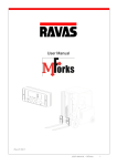
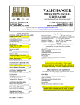
U
SER MANUAL
Manual 6163701-R2
C
ONTENTS
page
Introduction
1
Warnings & Safety Measures
2
Installation
3
Component Installation
3
After Component Installation
7
Check System Functions
8
Using Display
Functions
Other Features
9
10
Setup - Initial hWeigh System Setup
11
Using hWeigh System
16
Dos and Don'ts
17
Weighing a Load
18
Net weighing: Automatic Tare
19
Weighing a Load - Add to the Total & Reset
21
Options
i
9
22
Code Entry
22
Printer
23
User Settings
25
Parameters
28
Parts
30
Periodic Maintenance
31
6163701-R2
I
NTRODUCTION
This manual describes the assembly of the hWeigh
system. Read this manual carefully. The installer must
be informed of the contents of this manual. Follow the
contents of the manual precisely. Always do things in
the correct order. This manual should be kept in a dry
and safe place. In case of damage or loss, the user
may request a new copy of the manual from Cascade
RAVAS.
Display
The hWeigh weighing system consists of two main
components:
1. Display
2. hWeigh Valve
The hWeigh valve is installed in the truck hoist
hydraulic system. The display, the control panel of
the system for the driver, operates on 12 Volt DC or
24V-80V DC supply connected to the battery of the
truck. The illustration below shows the components in
the circuit.
It is advised that the installation of the hWeigh valve
by a local lift truck dealer.
hWeight Valve
Trucks with One
Center Mast Cylinder
Hoist Cylinder
hWeight Valve
Hoist Lower
Control Valve
Hoist
Control
Valve
Truck
Hydraulic
Pump
Hoist Cylinders
Trucks with Two
Side Mast Cylinder
hWeight Valve
Return
Return
Pressure
Hoist Lower
Control Valve
Pressure
Hoist
Control
Valve
Truck
Relief
Valve
Truck
Tank
AC2117.eps
6163701-R2
AC2116.eps
Truck
Hydraulic
Pump
Truck
Relief
Valve
Truck
Tank
AC2118.eps
1
W
ARNINGS & SAFETY MEASURES
When installing the hWeigh system, carefully read the
instructions and guidelines contained in this manual.
Follow the steps shown to install the hWeigh system on the
truck. If any of the instructions are not clear, please contact
Cascade RAVAS.
The installation of the hWeigh system should only be
performed by skilled personnel. Report equipment failures.
The equipment should be checked annually by skilled
personnel. Always follow the safety measures concerning
the lift truck accurately.
No riders
No reaching through mast
No standing under load
GA0434.eps
2
6163701-R2
I
NSTALLATION
Component Installation
IMPORTANT: Use good hoses for installation. Quality of hoses
can affect how the hWeigh system weighs loads.
Prior to installation, verify the following conditions are met:
• Truck is less then the rated capacity of 20,000 lbs (9,070 kg).
• Truck has a maximum pressure up to 3,500 psi (240 bar).
• Trucks with a battery voltage of 24 Vdc or higher, verify
display is labeled with "CONVERTER INSIDE".
WARNING: Before removing hydraulic
lines or components, relieve pressure in the
hydraulic system. Turn truck off and open
the truck auxiliary control valve(s) several
times in both directions.
1
Remove cable from negative
battery terminal
1 Disconnect the cable from the negative battery terminal
or as directed by OEM truck manual.
GA0436.eps
2
2 Install the fittings to the valve.
to No. 6 JIC.
Kit fittings are No. 6 BSP
No. 6 BSP
No. 6 JIC
AC2123.eps
Supplied Capscrews
3 Locate and install the valve on the truck cowl using the
supplied capscrews and washers. Holes should be
spaced 4.9 in. (110 mm).
IMPORTANT: Install valve with cartridges facing
downward. This prevents errors from occurring.
3
4.9 in.
(110 mm)
AC2124.eps
6163701-R2
3
I
NSTALLATION
Component Installation
4 Install a tee fitting in the mast cylinder supply line,
before the lowering control valve.
AC2125.eps
5 Determine length of hose and install between tee fitting
and valve "IN" port.
6 Determine length of hose and install between valve
One Center Cylinder
Two Side Cylinders
"OUT" port and trucks return tank line.
CAUTION: Do not place an oil filter in the return line of
the hWeigh valve.
7 Install a return-to-tank fitting in the tank line.
Lube
hose ends and fitting for easy assembly. For complete
installation procedure, refer to Installation Instructions
6808126.
Hoist
Cylinder
5
Hoist Lower
Control Valve
Trucks with Two
Side Mast Cylinder
Trucks with One
Center Mast Cylinder
Hoist Cylinders
5
6
hWeigh Valve
Tee Fitting
Hoist Lower
Control Valve
Hoist
Control
Valve
Install tee fitting
upstream of
Lowering Control
Valve
Install tee fitting
upstream of Lowering
Control Valve
7
hWeigh Valve
6
Tee Fitting
Hoist
Control
Valve
7
Returnto-Tank
Return-to-Tank
Truck
Hydraulic
Pump
Truck
Relief
Valve
Truck
Tank
AC2126.eps
4
Truck
Hydraulic
Pump
Truck
Relief
Valve
Truck
Tank
AC2127.eps
6163701-R2
I
NSTALLATION
Component Installation
8 If required, install the bracket to the display.
bracket/display assembly to the support.
Install the
FK0039.eps
5 mm
S5
13 mm
S13
9 Locate and mount the display.
Find a suitable location
for readout and easy access to display.
Cabin Roof
OR
Side Rail
OR
Dashboard
Display
AC2128.eps
6163701-R2
5
I
NSTALLATION
Component Installation
CAUTION: Consult the Lift Truck OEM for proper + power
source connection.
10
Route the sensor cable from the display to the hWeigh
valve. Connect the sensor cable to the valve sensor.
11
Route the solenoid cable from the display to the hWeigh
valve. Connect solenoid cable to solenoid.
10
11
12
Connect power cable to truck power source and route to
display.
AC2130.eps
12
Red (US)
Brown (EU)
Black (US)
Blue (EU)
Fuse
Switched
Truck
Fuse Block
13
Check all hoses and cable routing for pinch points.
14 Connect battery cable(s) to their proper terminal(s).
Truck
Battery
FK0084.eps
6
6163701-R2
I
NSTALLATION
After Component Installation
It's important that the truck be properly maintained to keep
the accuracy of the weighing. Check components are in
good condition:
• No wear in mast
• Mast and chains are lubricated
• Whistling and cracking sounds do not occur when the
lifting and lowering the forks
Maintain truck regularly per
OEM recommendations
When weighing load, mast
must be vertical and load is
free of obstacles
NOTE: A tilt indicator can be
installed to aid the driver in
aligning the mast at vertical.
Temperature Range:
15° F (-10° C) minimum
105° F (40° C) maximum
Never pressure wash
AC2133.eps
Cartridge Adjustment
1 Lift and lower the forks or attachment to maximum height
two times to remove air from the hydraulic system.
NOTE: Use a 19 mm wrench for cartridge cap removal and
adjustment.
2 Remove the protection cap of the flow adjustment valve.
3 Unlock the nut of the flow adjustment valve. Turn
clockwise to adjust flow speed when weighing a load.
1
2X
3
AC2131.eps
AC2132.eps
6163701-R2
7
I
NSTALLATION
Check System Functions
90°
1
2
Level mast
Press the on/off key.
Wait 5 seconds.
3
Lift forks or attachment
32 in. (80 cm)
4
The display will count down
4... 3... 2... 1... and calculate
the weight.
Press the weigh button.
AC2134.eps
If forks do not lower, adjust by
turning the cartridge counterclockwise
5
Forks will lower
AC2135.eps
Close
AC2136.eps
Open
NOTE: Install protection cap after
adjustments are made.
8
6163701-R2
U
SING DISPLAY
Functions
Left Side of Display
When
Right Side of Display
appears:
When the following
appears:
The weighing system
(including load) is stable
Weight shown is
in kilograms
The display is showing
the net weight
Weight shown is
in pounds
When
appears, the
weight shown is negative
Display
Button
Short Button Press
Low battery indicator
3 Second Button Press
Entry Mode
Zero Correction - Manually
zeros the display.
Code Entry - A 5-digit code
useful for a weighing system
connected to peripheral
equipment for later processing
Confirm Enter Value
Tare Weigh - Allows
the tare weights to be
reset to zero automatically.
Added and subtracted
weights can be determined.
NA
Decrease the value
of the digit flashing
Add/Total - Weighed load is
added to total weight. If printer
is installed, a printout is made.
Check subtotal and
print total
Increase the value
of the digit flashing
Weigh - Activates and
deactivates new weighing
mode.
NA
Shift to the next digit
on the left
On/Off switch - Turns the
display off
Clear entry
On/Off - Initially turns the
display on.
Also, in weighing mode, allows
the units to be changed between
kg and lb.
AC2142.eps
6163701-R2
9
U
SING DISPLAY
Other Features
Display Menus
Weigh Mode
Options:
Net Weight (Automatic Tare)
Add weight/Subtotal weight/
Total weight
Toggle units
Manual zero
On/Off Display
User Settings
Auto shut-off time
Light intensity
Deactivate/Activate Com Port 1
Deactivate/Activate Com Port 2
AC2152.eps
Select Weight Type
2
1000
Wait for units to
switch
kg➔lb
2205
1
Error Codes
Error on Display
Short press On/Off button
Meaning
Exiting Error Code Mode
Err01
Load cell signal is unstable
Disappears when signal is stable again
Err02
Overload n full weighing system
Disappears when overload is removed
Err04
Out of allowed range for zero correction
Press any key
Err06
Input signal too high
Check weighing system (load cells + cabling)
Err07
Input signal too low
Check weighing system (load cells + cabling)
Err08
Calibration out of range (negative)
Follow correct calibration procedure
Err09
Calibration out of range (signal too low)
Follow correct calibration procedure
Err10
Calibration count 2nd or 3rd point lower than count Follow correct calibration procedure
1st or 2nd point
Err97
Calibration locked
Contact Cascade
Err98
Calibration point must be higher than previous one
Follow the calibration procedure in order
Err99
Action only allowed in start-up unit (kg/lb)
Short press On/Off button
Negative weight
Lift forks/attachment from the ground
–––––
10
AC2153.eps
6163701-R2
S
ETUP
Initial hWeigh System Setup
Set Carriage Lowering Speed
1 Turn on the display by pressing the On/Off button and
wait 5 seconds.
2 With the forks or attachment empty, level the truck mast
and lift the carriage to the referenced height, shown.
IMPORTANT: For trucks with attachments, carriage and
attachment should be lifted to the middle of the mast.
3 Short press the Weigh button and wait the display to
count down.
4 The carriage should go down at a constant speed for
6-8 in. (15-20 cm).
• If the carriage does not drop, adjust the flow
adjustment valve. Refer to Cartridge Adjustment in
Installation section, Check System Functions.
NOTE: If the mast is older, it is recommended the
drop is shorter distance. For fine tuning, change
parameter setting 53 and 54. Refer to Parameter
Section.
5 Repeat Steps 2-4 with the forks or attachment loaded.
2
1
For Attachments:
Lift truck carriage to the
middle of the mast
90°
4
2
6-8 in.
(15-20 cm)
32 in. (80 cm)
AC2146.eps
AC2179.eps
3
6163701-R2
11
S
ETUP
Initial hWeigh System Setup
Mark Reference Height
1 Level the truck mast.
2 Lift the truck carriage so that the forks are 32 in. (80 cm)
above ground or the attachment and carriage height is
the middle of the mast.
IMPORTANT: When weighing a load, the carriage
will drop 8 in. (203 mm). For attachments, verify the
reference point allows for weighing drop based on the
height of the load.
NOTE: If the mast is older, it is recommended the drop
is shorter distance. For fine tuning, change parameter
setting 53 and 54. Refer to Parameter Section.
3 Clean areas that are visible from the truck cab, such as
side of mast and back of carriage.
For Attachments:
Allow at least 12 in.
(305 mm) clearance
from the ground to
allow for the tallest
load to be weighed.
12 in. (305 mm)
minimum
clearance
90°
1
4 Place lift stickers with points matching on the cleaned
surfaces.
2
32 in. (80 cm)
4
AC2143.eps
Stationary
AC2144.eps
Moving
12
6163701-R2
S
ETUP
Initial hWeigh System Setup
Truck Warm Up
Important: Prior to calibrating the system, refer to Using
hWeigh: Do's and Don'ts Section. The recommended
weight for setup is 2/3 of the truck's lifting capacity.
1 Level the truck mast.
2 With a load, lift the truck to the referenced height.
NOTE: If the load is greater than 441 lb. (200 kg), the
display will show a "-".
3 Press the Weigh button.
4 As the carriage drops, the display will count down and
2
90°
1
calculates the weight.
5 Repeat steps 2 - 4 for 2 minutes.
3
2
4
4
AC2145.eps
6163701-R2
13
S
ETUP
Initial hWeigh System Setup
Zeroing hWeigh System
1 Turn on the display by pressing the On/Off button and
wait 5 seconds.
2 Press and hold the Zero Correction button for more then
15 seconds.
3 The display will show "0_Adj'
4 Level the mast. With the forks or attachment empty, lift
the carriage to references height.
5 Press the Weigh button.
6 As the carriage drops, the display will count down.
1
2
3
NOTE: The carriage should drop 6-8 in. (15-20 cm).
7 After the display shows "0", the system has been
calibrated to zero. The display will automatically turn
back to weighing mode.
Reference
Height
4
5
6
90°
Reference
Height
4
AC2148.eps
6
7
AC2147.eps
14
6163701-R2
S
ETUP
Initial hWeigh System Setup
Point Calibration for hWeigh System
Point calibration should be performed every 6 months. For
new trucks, calibrate every 3 months. Some types of product
may require calibration more often. For varied loads with great
ranges, 3 point calibration may be necessary.
1
NOTE: Only one known weight is necessary for this step
(recommended); however, up to three weights can be used.
More points of calibration results in more accuracy (this does
not change the .05% accuracy). The load should be on the
forks/attachment prior to performing this step.
1 With display on and showing zero, press the Tare Weigh
button (about 30 seconds) until the cursor arrow flashes
over the "E1" and an initial weight value shows for the load.
2 Short press Enter (Zero Correction button) and enter the
Flashing
Cursor
Arrow
Change value using
Entry Mode Guide
2
A
value of the known weight for this calibration. Refer to Entry
Mode Guide.
AC2149.eps
3 By accepting the value, E1 will flash again.
4 Level the truck mast.
5 With a load, lift the carriage to the referenced height.
6 Press the Weigh button. As the carriage drops, the display
Entry Mode Guide
will count down and store the weight.
7 One Point Calibration - Short press the totalling button two
times until "AP_X" shows (X being a number value).
Two or Three Point Calibration - If more then one known
weight is being used for calibration, repeat steps 2 through
7 for the additional weight(s) by pressing the totalling button
once. The arrow above E2 or E3 should be flashing.
C
A
90°
5
6163701-R2
4
B
5
6
OR
Decrease Increase
the value the value
Reference
Height
AC2154.eps
B
A
For flashing digit (A), while in entry
mode, pressing buttons:
Shift to the next
digit on the left
C
Accept the value
AC2150.eps
6
7
AC2151.eps
15
S
ETUP
Initial hWeigh System Setup
9 Press the enter button. "Zone" will appear on the display
and a gravitational value will show.
10
Leave the value as is and press the Enter button.
11
Unload the truck and raise the carriage. The display
should show zero after 5 seconds. If a weight shows,
short press the zero button to correct the display
reading.
8
9
16
AC2155.eps
6163701-R2
U
SING hWEIGH SYSTEM
Dos & Don'ts
PRIOR TO WEIGHING
Verify forks (or attachment)
are free of obstacles prior
to zeroing
Position to vertical
With the carriage at
referenced height, verify
display shows zero
Verify carriage
is lifted to
referenced height
Level load to
Horizontal
AC2156.eps
WEIGHING
Wait for display
to zero
NOTE: The accuracy of the weight on
the display is within .05% of maximum
capacity of the truck.
15° F (10° C) minimum
105°F (40° C) maximum
Center load on forks and
pallet, load must be flat
AC2157.eps
AC2158.eps
6163701-R2
AC2159.eps
17
U
SING hWEIGH SYSTEM
Weighing a Load
IMPORTANT: Always lift the carriage to the referenced
height. Zeroing the display will not zero the hWeigh
system. The hWeigh system is calibrated by hydraulic
pressure.
To Activate Weighing System:
1 Pick up a load and level the truck mast.
IMPORTANT: The load should be centered with the
truck mast and fork/attachment center of gravity.
2 Lift carriage to referenced height.
3 Short press the Weigh button.
AC2180.eps
NOTE: Bouncing of the carriage will affect the
weighing.
Press the On/Off key
4 The truck carriage will lower and the display will count
NOTE: To turn off the display, hold the
On/Off Button for 3 seconds.
down.
5 The display will show the weight.
CAUTION: Always switch off the
display before turning off the truck.
NOTE: For loads weighing less than 441 lb. (200 kg),
the display will show a fixed value for 5 seconds. After
5 seconds, the display will switch to dynamic weighing
mode.
Dynamic Weighing Mode
When the forks/attachment are being unloaded, the display
switches to dynamic mode. The display shows the actual
oil pressure, not calculated weight. If the load weight is
greater than 441 lb. (200 kg), the display show "-".
To get out of dynamic mode, weigh a new load.
Zeroing
To check system is zeroed, lift forks or attachment, without
a load, to the reference height. Once the forks stop, wait 5
seconds:
• If the display shows greater then 22 lb. (10 kg), short
press the Zero Correction button. The display should
show zero.
• If the display shows "Err04", the system will need to
be calibrated. Press the Zero Correction buton ro exit
the error code.
3
90°
1
AC2154.eps
2
Reference
Height
4
1
4
5
AC2160.eps
18
6163701-R2
U
SING hWEIGH SYSTEM
Net Weighing: Automatic Tare
To weigh a load but disregard part of the total load's
weight (pallet, bin, etc):
90°
1 Pick up the load to be disregarded. Example: a pallet or
2
bin without a load. Level the mast.
2 Lift carriage to referenced height.
3 Short press the Tare Weigh button.
4 Short press the Weigh button.
5 The truck carriage will lower and the display will count
Reference
Height
1
down.
6 The display will show the "0" and an arrow will appear
next to the "NET" sign on the display.
AC2162.eps
4
3
5
5
6
AC2161.eps
Arrow will appear
next to "NET"
6163701-R2
19
U
SING hWEIGH SYSTEM
Net Weighing: Automatic Tare
7 Pick up a load to be weighed (including the load to be
disregarded). Level the mast.
8 Lift carriage to referenced height.
9 Short press the Weigh button.
10
The truck carriage will lower and the display will count
down.
11
The display will show the weight.
90°
9
8
Reference
Height
7
10
AC2163.eps
11
10
Deactivate Automatic Tare
To deactivate Automatic Tare:
1 Short press the Tare button.
2 Short press the Weighing button.
3 The arrow next to "NET" will disappear and the display
will resume to basic weighing mode.
1
20
2
NET arrow will
disappear
3
AC2164.eps
6163701-R2
U
SING hWEIGH SYSTEM
Weighing a Load - Add to the Total & Reset
Adding a Weight:
4
2
5
3
Short press to
Add/Total button
Sequence Number shows
(Number of Weighings)
1
Weigh a load
Display will show
"Added"
6
Subtotal shows
Value is
stored and
added to
memory
7
Display
returns to
weighing
mode;
Repeat for
each load to
be added. ★
★ NOTE: In between weighings the
display will be in dynamic mode.
Wait for 44 lb. (20 kg) to show before
weighing next load.
IMPORTANT: The display can not (sub)total or print
out when in dynamic mode. When the display shows
a weight less then 441 lb (200 kg), press the Add/Total
button within 5 seconds of weight calculation.
AC2165.eps
Subtotal and Totalling:
If one of the buttons is pressed
during flashing:
Hold for 3 seconds
During the next
few seconds, the
following flashes:
Total is reset
Number of items weighed
NOTE: If no button is pressed during
the flashing, the subtotal stays in
memory, and the system returns to
the weighing mode.
Subtotal
6163701-R2
For printer option, total is
printed and total is reset
AC2166.eps
21
O
PTIONS
Code Entry
Entry of codes are useful for a weighing system that is
connected to a printer or other peripheral equipment. This
aids with identifying various weighings for later processing.
Entry Mode Guide
1 Press and hold the ID CODE (Zero Correction button)
for 3 seconds.
2 The display will show the last used code. The right digit
will flash.
3 To accept the current value, short press Enter (Zero
Correction button) or hold Enter for 3 seconds. Use
Entry Mode Guide to change the value.
NOTE: To not have a code printed out, change the
value to "00000".
4 When the same or new value is accepted, the display
C
B
A
For flashing digit (A), while in entry
mode, pressing buttons:
A
will return to Basic Weigh mode.
OR
Decrease Increase
the value the value
B
1
Change value using
Entry Mode Guide
Shift to the next
digit on the left
C
Accept the value
AC2150.eps
3
AC2181.eps
22
6163701-R2
O
PTIONS
Printer
Print Weight
B/G
T
N
2
250.0 kg.
25.0 kg.
275.0 kg.
Nr.1
10/15/0917:45
Press total button
to print
3
Printer will print
out load weight
1
Weigh load
250
kg
NOTE: This will add the weight to
the total weight.
AC2167.eps
Print Total Weight
Tot. B/G2000.0 kg.
Tot. T
50.0 kg.
Tot. N 1950.0 kg.
Tot. Nr.5
10/15/0917:55
AC2168.eps
1
6163701-R2
Hold Total button
for 3 seconds
2
As the display switched
between sequence
number and subtotal/
total, short press to
print
3
Printer will print
out load weight
and the display
memory will be
set to zero for
both sequence
number and
weight total.
23
O
PTIONS
Printer
Change Time & Date Printout
2
Change current settings (shown in entry
mode guide). To accept current settings,
press the enter button.
Time Setting: Hour
1
Hold for 8
seconds
Time Setting: Minute
Entry Mode Guide
Date Setting: Day
C
B
A
For flashing digit, while in entry mode,
pressing buttons:
A
OR
Decrease Increase
the value the value
Date Setting: Month
C
B
Shift to the next
digit on the left
Accept the value
Date Setting: Year
AC2169.eps
Change Units Printout
AC2170.eps
Short press CLR
button
24
Current weight in new units
will show for 5 seconds.
The display will change
back to the start up units
6163701-R2
O
1
PTIONS
User Settings
Enter user settings
Multiple screens
will flash
2
Choose a menu option
User Settings
Menu Mode
3
Continue to
desired
submenu
(see next
page)
AC2171.eps
Hold for 10 seconds
4
Select menu
option
Scroll through
menu options:
Auto Shut-Off Time (Display)
Light Intensity
Deactivate/Activate Com Port 1 (Bluetooth board)
Deactivate/Activate Com Port 2 (Printer board)
Exit menu
Exit & Save:
Changes are being saved
Hold for 3 seconds
Weigh Mode
OR
Exit without Saving:
AC2172.eps
Weigh Mode
Press CLR button
6163701-R2
25
O
PTIONS
User Settings
Auto Shut-Off Menu (Display)
NOTE: Auto shut-off can be set to 0 only when the display
is hardwired to the truck power. If not hardwired, the
display will remain on.
1
Selected digit
(minutes) flashes
2
3
AC2173.eps
Enter auto
shut-off menu
Move over
digit, left
Accept
Value
Decrease
digit value
Backlight Intensity Menu
1
Increase
digit value
3
2
AC2174.eps
Enter backlight
intensity menu
Accept
Value
When value
is accepted,
indicator will
return to User
Settings Mode
Menu
Move down Move up
through list through list
When value
is accepted,
indicator will
return to User
Settings Mode
Menu
Intensity options:
0 (Backlight Off), 25, 50 ,75, 100
Com Port 1 Menu
1
Com Port 1 can not be
de-activated
AC2175.eps
Enter Com Port
1 menu
26
Accept
Value
Move down Move up
through list through list
Options:
C10ff – De-activate Com Port 1
C1_on – Activate Com Port 1
3
When value
is accepted,
indicator will
return to User
Settings Mode
Menu
6163701-R2
O
1
PTIONS
User Settings
Com Port 2 Menu
2
3
AC2176.eps
Enter Com Port
2 menu
6163701-R2
Accept
Value
Move down Move up
through list through list
Options:
C20ff – De-activate Com Port 2
C2_on – Activate Com Port 2
When value
is accepted,
indicator will
return to User
Settings Mode
Menu
27
P
ARAMETERS
To enter the parameter menu: With the display on, hold the ON/OFF key
until "P_ _00" shows in the display (about 30 seconds).
To leave the parameter menu and store all entries: Press the ON/OFF
key TWO times shortly. Switch off and restart the display to activate
new settings.
Default Settings
Parameter Function
EU
US
01
Weight unit (Calibration, Start-Up, Print)
1
2
1 = kg, 2 = lb
02
Smallest graduation step for multirange
2
5
0.1, 0.2, 0.5, 1, 2, 5, 10, 20, 50
03
Biggest graduation step for multirange
2
5
0.1, 0.2, 0.5, 1, 2, 5, 10, 20, 50
04
Number of divisions for every range
1000
1000
0000–9999 divisions
05
Weighing capacity system (full scale)
2500
5000
0–99999
09
Zero range positive (+)
10
10
0–100 % of span
10
Zero range negative (-)
10
10
0–100 % of span
11
Test function (display service mode)
basic
basic
12
Power on – automatic zero
no
no
yes, no
13
Approved/Non-approved version
no
no
no, ntep, oiml
no
no
not active
yes
yes
no, yes
0
0
not active
4
4
4, 6
9.812
9.797
EU
US
14
15
Units switch mode active
16
28
Available Setting Options
basic, count, res10
17
Number of wires per loadcell (sense active)
18
Gravity value working area
19
Print format date/time
20
Baudrate com1
9600
9600
600, 1200, 2400, 4800, 9600, 19200
21
Setting com1
8_n_1
8_n_1
8_n_1, 8_n_2, 7_n_1, 7_n_2
24
End character com1
cr
cr
cr, lf, crlf
25
Protocol com1
5
5
0 (PC bi-directional NU),
1 (PC Excel format on print command),
2 (remote display),
3 (printer protocol with power control),
4 (printer protocol without power control),
5 (not active),
6 (PC Excel format with ack/nack)
26
Number of linefeeds com1
4
4
0–9
27
Handshake com1
soft
soft
soft (Xon/Xoff), hard (CTS)
28
Printout format for com1 and com2
stnd
stnd
stnd, total, confi
29
Header lines added
0
0
30
Baudrate com2
9600
9600
600, 1200, 2400, 4800, 9600, 19200
31
Setting com2
8_n_1
8_n_1
8_n_1, 8_n_2, 7_n_1, 7_n_2
34
End character com2
cr
cr
cr, lf, crlf
35
Protocol com2
0
0
0 (PC bi-directional NU),
1 (PC Excel format on print command),
2 (remote display),
3 (printer protocol with power control),
4 (printer protocol without power control),
5 (not active)
6(PC Excel format with ack/nack)
9.750–9.850
EU (dd/mm/yy), US (mm/dd/yy)
0–3
6163701-R2
P
ARAMETERS
Default Settings
Parameter Function
EU
US
4
4
Available Setting Options
36
Number of linefeeds com2
0–9
37
Handshake com2
soft
soft
soft (Xon/Xoff), hard (CTS)
40
Level sensor
no
no
no/ls nc/ls no/cs fa/cs ra
41
Delay trigger time level sensor
3
3
0-10 sec
49
Underload % of FS
20
20
0 to 100 % of span
53
Time interval weighing hWeigh
1.5
1.5
1.0-2.5 sec
54
Delay time weighing hWeigh
2.5
2.5
1.5-3.0 sec
55
Threshold value hWeigh
200
200
20/50/100/200/500/1000/2000/5000/10000
59
Measuring frequency
80
80
10 or 80 Hz
60
Battery used
12
12
6V, 12V
61
Low Bat switch-off time
2
2
0 (never off), 1-99 min
62
Auto shut-off time indicator
30
30
0 (never off), 1-99 min
65
Auto shut-off time backlight
20
20
off, 20, 40, 80, 160, 320 sec
66
Backlight brightness
100
100
100, 75, 50, 25, 0% (off)
68
Buzzer function active
off
off
off, on (direct), on (2 sec delay)
90
Default settings without changing calibration
91
Default settings with erasing calibration
93
Read out last 10 error messages
96
Printout parameter setup
Pr-C1
Pr-C1
97
Key Test Function (buzzer and nr)
98
Scale ID number
0
0
99
Software version
Pr-C1, Pr-C2
0-999
For older masts:
To fine tune an older mast, parameters 53 and 54 can be
adjusted.
Parameter 53 – The time that the system uses to weigh
the load. For example, in situations where the mast lowers
a shorter distance, the time should be set to a shorter time
than the default.
Parameter 54 – The time before the system begins to
weigh the load. For example, in situations where the mast
lowers a shorter distance, the time should be set to a
shorter time than the default.
6163701-R2
29
P
ARTS
hWeigh Parts
*
(
)
%
$
5
^
3
&
#
4
T
OU
IN
12
AC2221.eps
7
!
6
0
9
8
@
12V
24V-80V
REGULATOR
PART NO. 1
TOP LEVEL
PART NO.
CONVERTER
PART NO. 2
TOP LEVEL
PART NO.
PRINTER
PART NO. 3
OTHER
ON-BOARD
PART NO. 4
Standard
■
6163708
■
6163714
—
—
Thermal Printer
■
6163709
■
6163715
6161995 ◆
—
Dot Matrix Printer
■
6163710
■
6163716
6156462 ◆
—
RS232 Data Output
■
6163711
■
6163717
—
■
Bluetooth Data Output
■
6163712
■
6163718
—
■
Wi-Fi Data Output
■
6163713
■
6163719
—
■
OPTIONS ▲
▲ When ordering a new display, use the top level part number along with the following part numbers: Regulator (item 1) or Converter (item 2),
Printer (item 3) or On-Board (item 4), Indicator (item 5) and cables (items 6 & 7).
◆ See Printer page for parts breakdown.
■ Contact Cascade Service Department.
Common Parts
REF QTY
5
6
7
8
9
10
11
12
30
1
1
1
1
1
1
1
2
PART NO.
6155856
6163591
6163588
6163571
6163574
6163575
6163582
6163596
DESCRIPTION
Display
Cable, Pressure Transducer
Cable & Plug, Solenoid
Valve Block
Flow Adjustment Valve
Pressure Transducer
Solenoid Valve
Adapter Fitting
l Includes in hWeigh Common Parts 6163704.
REF QTY
PART NO.
DESCRIPTION
13
14
15
16
17
18
1
1
1
2
2
4
6163598
6155854
6155861
767961
787384
768781
Lift Sticker, pair
Mounting Bracket
Mounting Bracket
Capscrew, M8 x 16
Lockwasher, M8
Capscrew, M5 x 16 ●
19
20
8
4
6156029
212273
Washer, M5 ●
Nut, M5 ●
6163701-R2
P
ARTS
hWeigh Printer Parts
23
1
Thermal Printer, 12V
REF QTY
1
2
3
AC2083.ai
1
1
1
PART NO.
6161995
6161762
6161763
DESCRIPTION
Thermal Printer, 12V
Printer Paper, 5 Roll Pack
Stick On Printer Paper, 2 Roll Pack
1
Dot Matrix Printer
REF QTY
1
1
PART NO.
6156462
DESCRIPTION
Dot Matrix Printer
AC2082.ai
P
ERIODIC MAINTENANCE
Maintenance of the mast, mast cylinder, chains, etc.,
makes a difference in how hWeigh performs. Accuracy of
hWeigh is dependant on the quality of the truck.
IMPORTANT: The mast must be working at optimal levels.
In addition to the truck OEM maintenance schedule
perform the following:
100-Hour Maintenance
Every time the lift truck is service or every 100 hours of
the truck operation, whichever comes first, complete the
following maintenance procedures:
• Check for pinched wires and hoses.
1000-Hour Maintenance
After each 1000 hours of truck operation or intervals of 6
months (whichever comes first), in addition to the 100-hour
maintenance, complete the following maintenance
procedures:
• Check calibration for accuracy. Recalibrate, if
necessary.
6163701-R2
31
Do you have questions you need answered right now?
Call your nearest Cascade RAVAS Service Department.
Visit us online at www.cascorp.com
AMERICAS
Cascade Corporation
Parts Sales
2501 Sheridan Ave.
Springfield, OH 45505
Tel: 888-CASCADE (227-2233)
Fax: 888-329-0234
© Cascade RAVAS 2011
Cascade Canada Inc.
5570 Timberlea Blvd.
Mississauga, Ontario
Canada L4W-4M6
Tel: 905-629-7777
Fax: 905-629-7785
10-2011
Part Number 6163701-R2