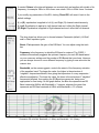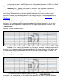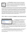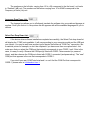
1
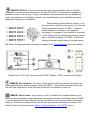
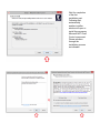
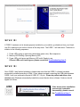
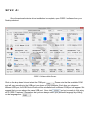
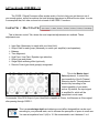
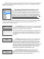
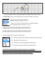
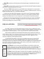
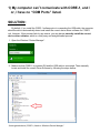
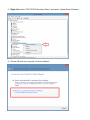
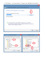
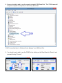
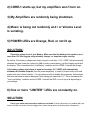
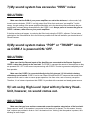
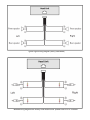
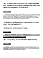
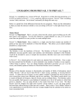
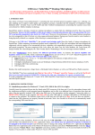
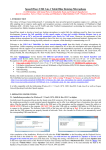
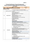
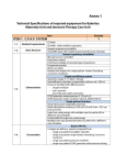
User’s Manual Introduction: Congratulations! And thank you for purchasing the CORE-1 Signal Processor, a complete audio signal processing and power management solution for whose seeking performance, customization and OEM integration. The CORE-1 features the newest Analog Devices DSPs for state-of-the-art music reproduction, at the same time providing you with endless tweaking capabilities by the infinite settings and combinations of Parametric Equalizer, Time Alignment, Multiple Crossover choices and much more. Additionally, the CORE-1 fully protects your vehicle’s electrical system and audio system components against low battery voltage and blown speakers. Features: 1) 8 Fully configurable output channels capable of 4V RMS (12.5Vpp) RCA output swing. 2) 8 Summing Input channels compatible with Low-Level & High-Level input types; 3) Bluetooth Audio Streaming with Apt-X codec for audiophile audio quality; 4) State-of-the-art Audio Reproduction: 24-bit resolution ADC / DACs; 56-bit double precision signal processing Frequency Response from 10 to 22Khz +/- 1 dB THD < 0.003% SNR > 93 dB 5) Audio Signal Processor: Precision Crossover System: Linkwitz-Riley, Bessel and Butterworth topologies, 12, 18, 24, 36 and 48 dB / octave crossover slopes available; Full Pass / High Pass / Low Pass / Band Pass / Peaking / Shelving filters; Up to 96 Parametric Equalizer Bands with adjustable Frequency and Bandwidth; Full Time Alignment Correction and Phase rotation; R.M.S. Limiter with adjustable Threshold, Attack and Decay 6) Power Management Processor with fully automated actions for Low Battery and Very Low Battery conditions, with adjustable voltage threshold levels. Installing the CORE-1 Signal Processor: WARNING: Installation of this mobile audio device requires experience with a variety of mechanical and electrical procedures. If you don’t have the required knowledge / experience to complete the installation, please consult an authorized Massive Audio dealer about professional installation option. Before you begin, please note the following: 1) Install the software BEFORE you connect the USB cable. Insert the CD Software, open “Core1_Installer.exe” and proceed clicking “Next” till the end. Please consult “Software Installation”. 2) Connect CORE-1 directly to the battery (12Volt DC). Do not power it from the ignition switch or any type of switch. Please consult “Power Source Connector”. 3) Make SURE that your vehicle’s battery is fully charged. We strongly recommend using a battery charger during the setup process. If the battery voltage is lower than 11.5V, the CORE-1 protection features will kick in and may cause confusion. Please consult “Power Manager”. 4) If you use the High Level Input, you don’t need to connect the remote wire input “REM”. CORE-1 features “auto-remote.” Please consult the “Wiring Diagram” for High Level audio inputs. 5) ALWAYS connect the REMOTE of the amplifiers to the CORE-1. Never from the Head Unit. Utilize outputs “REMOTE OUT” 1 to 4. Please consult “Remote Outputs”. 6) Set the GAIN of the Power Amplifiers to ZERO to avoid “hiss” noise. CORE-1 already pre-amplifies the signal. Always prefer to adjust the gain utilizing the software. Please consult “RCA Audio Outputs”. OVERVIEW / HARDWARE INSTALLATION: INPUT PANEL: Power Source Connector Computer USB Connector Bluetooth Audio Connector Bluetooth Audio Volume RCA Audio Inputs OUTPUT PANEL: RCA Audio Outputs Memory Select Button Remote Connector Remote Outputs REMOTE CONTROL & LED INDICATORS: Memory Slot Indicators Memory Select Button Gain control Knob Limiter Actuation LEDs Power Indicator LEDs SOFTWARE INSTALLATION UTILIZING CORE-1: INPUTS / OUTPUTS TAB: Master Input Gain Sound Stage Depth Output Group Type Output Gain Balance Control Time Alignment Controls Time Alignment Calculator Crossover Settings Output Type Output Phase V.U. Meters / RMS LIMITER TAB: V.U. Meter R.M.S. Limiter o Threshold o Attack o Decay GROUP EQUALIZERS (1 to 4) TABs EQ Bands Reset EQ Side Selection: (L+R), (L), (R) Boost / Cut Frequency Bandwidth Parametric Hi-Shelf Lo-Shelf POWER MANAGER TAB Voltage Readings Power Source Selection Low Battery Condition Very Low Battery Condition Volts: Set (Action Start Voltage) Volts: Clear (Action Stop Voltage) Action to take (automatic action) Startup Delay (sequential Power On) Manually Selecting Remote ON / OFF TOP MENU: SAVE / LOADING settings to / from CORE-1 Frequency Response Graph Language Selection COM PORT Selection TROUBLESHOOTING: Device Driver Software Amplifiers won’t turn ON Amplifiers being shutdown randomly Music Volume Level varying Power LEDs are Orange / Red / OFF Limiter LEDs constantly ON Excessive HISS noise “POP” and / or “THUMP” noise Absence of sound when using High Level Input Non Synchronized Power ON / OFF with Head Unit Bluetooth Volume Level doesn’t Match Head-Unit’s Bluetooth Audio sounds “noisy” Can’t Pair my Phone with CORE-1 Bluetooth OVERVIEW / HARDWARE INSTALLATION: Input Panel. Power source connector: Connect to your vehicle’s battery and head-unit. Utilize a small flat screwdriver to secure the wires connection to the plug. The plug is connected “up side down” to the Unit, so make sure to follow the correct connection order as shown on the picture bellow: GND: Connect to vehicle’s ground; REM: Remote wire input, connect to the Head Unit blue wire. DO NOT use in case CORE-1 is being used with a “High-Level” audio source. +: Connect directly to +12V of the vehicle’s battery. DO NOT power Core-1 from a switched power source. CORE-1 needs constant power in order to work properly, AUX: If you have an auxiliary battery, connect to the +12V. Tip: Voltage readings can be observed at the “Power Manager” tab on the software. Computer USB Connector: Connect to the computer after successful software installation. This is how CORE-1 communicates with your computer. Make sure that you have successfully installed CORE-1 software, only then, you should proceed connecting the CORE-1 unit to the computer using the supplied USB cable. Bluetooth Audio Connector: Insert the provided Bluetooth Audio module. By utilizing the supplied Bluetooth Audio module, you will be able to stream high-quality audio directly to CORE-1 by pairing it with your cellphone. Make sure that the Bluetooth is enabled on your phone. Search for Devices and you will find CORE-1. If not successful, please refer to the Troubleshooting item 13. Bluetooth Audio Volume: Begin by setting it to the middle. This volume control is meant to help you balance the volume of your Bluetooth audio device with your Head-Unit. Although CORE-1 comes with the volume set at the maximum level, we strongly recommend that you set the volume at the middle and then, proceed making small adjustments to satisfy your listening preference. RCA Audio Inputs: Connect to the audio output of your head unit, which can be either a factory or an aftermarket model. These inputs are also compatible with Low Level audio, which you should use with good quality RCA cables, as well as compatible with High Level audio, which you should use the supplied “RCA to High Level” adapter cables. The inputs are “summed”, which guarantees perfect compatibility with factory head-units by combining the frequencies of each channel, resulting in the reconstitution of the full-range audio that will be further processed by the CORE-1. In case you’re using Low Level (or line level), make sure that you connect at least one pair (Left / Right) of RCA cables from the RCA Outputs of your Head-Unit to the RCA Inputs of CORE-1. In case you’re using High Level (or speaker level), use the supplied “RCA to High Level” adapter cables to connect CORE-1 to the speaker wires of your head-unit. Please make sure to properly match the phase (+/ -) and sides (left / right) in order to have a good listening experience. We recommend to place the supplied “Dummy load” resistors across the (+) and (-) wires of the head unit speaker output, basically “taking place” of the speaker that was originally installed. Please consult the “Wiring Diagram” here. Some cars need this to “trick” the Head Unit into thinking that the speaker is still present, thus allowing music to be played through the speaker wires. Equally important, please do not use the REMOTE input of the Power source connector. The CORE1 features “AUTO-REMOTE”, which exempts the use of the REMOTE wire because it senses when the factory head-unit has been turned ON or OFF. Output Panel. RCA Audio Outputs: Connect to the RCA Inputs of your amplifiers, observing the correct Left and Right sides, as well as the output group numbers (1 to 4). Capable of up to 4 V R.M.S. (12.5 V.P.P.), the CORE-1 is an efficient Line Driver that will ensure that the signal is pre-amplified enough before reaching your amplifiers, consequently, better overall Signal-to-Noise ratio is achieved, ensuring the best music enjoyment with dynamic, clear, and low-noise signal. Make sure that the gain control of your power amplifier is set to the minimum, to prevent your amplifiers from saturating due to the strength of the signal output by CORE-1. In case of hiss or noise, please consult Troubleshooting Item 7. MEMORY Select button: Use to switch “on-the-fly” between the 3 available Memory slots. Once you have successfully created and saved your personal settings to the Memory slots of CORE1, you can always choose which Memory slot you would like to use at any time, without needing the computer. Please consult “Saving / Loading settings to / from CORE” section. REMOTE Connector: Connect to CORE-1 Remote control by utilizing the supplied cable. With the CORE-1 Remote control you will be able to operate the MEMORY Select button as described above, as well as adjust the Gain of the Output group(s) chosen by you, which could be the gain of your Subwoofer for example. REMOTE OUTPUTs: Connect to the Remote Input of your amplifiers. Utilize a small flat screwdriver to secure the wires connection to the plug. The CORE-1 must be able to manage the amplifiers in order to ensure “pop” / “thump” free operation. We recommend only one amplifier per output, thus maximum of 4 amplifiers. However, you can definitively use two amplifiers per output, allowing for a maximum of 8 amplifiers. Please observe that the Remote outputs (1 to 4) are associated to the RCA output groups (1 to 4) by the Power Management System of CORE-1. Therefore, please make sure to connect to your amplifiers accordingly. For example, if your amplifier is connected to RCA Output Group 2, proceed connecting its remote input to the Remote Output 2 of CORE-1, so both the Audio and Remote controls belong to the same group. Tip: Power On delay and state configurations available at the “Power Manager” tab on the software Remote Control TOP (Left), Remote Control FRONT (Middle), CORE-1 Indicator LEDs (Right) MEMORY Slot indicators: The Green, Yellow and Red LEDs are indicators of which of the three available Memory presets is being used by the CORE-1. These LEDs are present both on the unit itself (see image above, at the right side), as well as on the Remote Control unit. MEMORY Select button: Use to switch “on-the-fly” between the 3 available Memory slots. Once you have successfully created and saved your personal settings to the Memory slots of CORE1, you can always choose which Memory slot you would like to use at any time, without needing the computer. This button is present both on the unit itself (as previously mentioned) as well as on the Remote Control unit. Please consult “Saving / Loading settings to / from CORE” section. GAIN CONTROL knob: Use to control “on-the-fly” the gain (volume) of the desired output group(s). By default, CORE-1 comes with the knob assigned to all four output groups, however you can (and should) change it at any time by utilizing the software. On the lower left corner of the software, you can use the check-boxes to select the output group(s) that the knob will be able to control. For example, if you’re utilizing a subwoofer on Output Group-1 and you wish to control its volume with the knob, then you check only “1” and leave the other groups unchecked, as shown by the example picture on the left. Limiter Actuation LEDs: Please consult the “Limiters” section. Whenever the Limiter(s) start compressing the music signal to protect your system, the corresponding Yellow LED(s) will light up. Each LED corresponds to its respective Output Group. For example, if the Limiter of Group-2 starts to work, the Limiter LED number 2 will light up. POWER Indication LEDs: Please consult the “Power Manager” section. These LEDs notify you of your vehicle’s battery condition. If the battery voltage level is OK, these LEDs will be Green. If the battery voltage level is running low, LED(s) become orange. If battery voltage level is very low, LED(s) become Red for selected actions other than “shutdown”, or, if the “Power Manager” shuts down the remote output(s), the corresponding LED(s) will be OFF. SOFTWARE INSTALLATION: Step 1: Please install the CORE-1 Software by advancing through the installation process as indicated: Wait for completion of the first installation part. Following that, automatically another installer window will open to install the necessary Microsoft.NET Chart Control component. Please advance through the installation process as indicated: Step 2: If CORE-1 hardware unit is already properly installed on your vehicle, go ahead and turn your HeadUnit ON, make sure you set the Volume all the way down. The CORE -1 will take about 7 seconds to initialize in the following sequence: 1- Power LEDs going up and down (alternating green color): Boot sequence; 2- Memory LED blinking: Opening Memory Slot; 3- Power LEDs solid green and Memory LED solid: Ready to use. If Power LEDs aren’t solid green, please consult the Troubleshooting Item 5. Step 3: Once CORE-1 has finished initializing, please make sure that the CORE-1 software has been successfully installed according to Step-1. Now, please proceed connecting the USB cable between CORE-1 and your preferred computer’s USB 2.0 / 3.0 port. Please be patient and allow a few minutes while Windows automatically installs the correct device driver software. A baloon should appear as follows: If the device driver installation process don’t complete successfully, please consult the Troubleshoot item 1. Step 4: Once the automatic device driver installation is complete, open CORE-1 software from your Desktop shortcut: CORE-1 Software Main Screen Click on the drop down list and select the COM port: Please note that the available COM port will vary according to the USB port you chose on your computer. Each time you choose a different USB port, the USB Device Driver will be reinstalled and a different COM port will appear. We suggest that you use always the same USB port. Now, click and you’re ready to fully enjoy all of CORE-1 features! Remember that you can always select your preferred language by clicking on the language box: Utilizing CORE-1: The CORE-1 Signal Processor offers a wide variety of tools to help you get the most out of your sound system, as well as achieve the best listening experience in different music styles. In order to accomplish that, let’s take a closer look at each of the CORE-1 functions: Inputs / Outputs: This is the main control Tab, where the most important adjustments are realized. These adjustments are: Input Gain (Necessary to match with your Head Unit); Output Gain for each group (Necessary to match your amplifer(s) and speakers); Balance; Time Alignment; High Pass / Low Pass / Speaker type selection; Output type and phase; Stage Depth widening effect (optional); Remote Control gain knob group(s) assignment. This is the Master Input Gain adjustment. It controls the input sensitivity of the 8-Channel Summing inputs. This adjustment should vary according to the output capability of your audio source. By default, the input signal is amplified 2x, which will be apropriate in most cases. For example, if the RCA Output of your Head Unit is capable of 2Vrms, it will become a 4Vrms signal after passing through CORE-1. This is a sound stage depth and widening sound effect designed that can be used according to your personal taste, and to increase the perception of space in small cars. You can set anywhere from 0 (off) to 10. We recommend to use it between 1 to 4. CORE-1 features 4 stereo output groups (8-CH RCA outputs). Each group can be individually configured to suit the type of transducer (speaker) that you wish to use, for example, subwoofers, midbass, tweeters and more. By selecting one of the listed types of transducers, CORE-1 will automatically suggest parameters for Low Pass, High Pass and Output Type settings. These parameters will work well with most products on the market. However, depending on your level of expertise, you can always choose “Custom” and using your best judgment and professional experience, choose optimal parameters for your particular application. Be aware that high-frequency transducers are prone to damage when subjected to frequencies below their recommended range of operation. For example, a tweeter without an appropriate High Pass filter is likely to suffer permanent damage. Hence, if you want to go “Custom”, make sure you read carefully the specifications of your transducers prior to CORE-1 operation. The output Gain works as a “volume control”. It controls the signal amplitude on each corresponding output group, thus controlling the signal intensity that the amplifier receives from CORE-1. Once you have selected the types of transducer that are being utilized on each output group, for example, Subwoofer, Mid-Bass and Tweeter, you can adjust the sound intensity level of each according to your musical preference. The Balance Control should be used to set the ideal gain levels for Left ( L ) and Right ( R ) channels of the output group. Ideally, the sound emitted from the speakers of both left and right sides must reach the listener’s position (usually the driver) with the same intensity level. However, inside the car cabin the left speaker is always closer to than the right speaker, leading to a small mismatch between the two. In order to correct that and have a perfect listening experience, you can always compensate for this difference using the balance control. The Time Alignment controls should be utilized in order to compensate for the non-uniform physical distances between the transducers and the listener. In other words, the distance between the listener and the speakers inside the car always differ. By using Time Alignment correction, CORE-1 digitally compensates for these differences in distance, leading to a perfect listening experience, as if the speakers where all physically aligned to each other. A simple and effective way to perform Time Alignment and Balance correction is available by utilizing the calculator built-in the software. Beforehand, please set your preferred measurement unit. You can choose to enter measured distances in Inches (USA) or Centimeters (other countries). Go to: File Set Measurement Units. Then proceed opening the calculator. Go to: File Time Alignment and Balance Calculator. Now, all you have to do is to sit as the driver and measure the distances between you facing forward and the transducers (speakers) in your car. Enter the distances found on the “Measured Distance” fields and hit “Calculate!” CORE-1 will automatically calculate and apply optimum values for Balance and Time Alignment, so you don’t have to worry about doing it manually. This will result in perfect soundstage, as if all speakers were perfectly aligned and at the same distance from the listener. The picture on the left shows a typical example of a 3-Way system alignment using Subwoofer, Mid-Bass and Tweeters. If you wish to perform the Time Alignment manually, just drag the sliders corresponding to the delay-distance on the (L) and (R) sides until you get appropriate soundstage imaging. You can also type the distance-delay that you wish to achieve by typing inside the fields and then pressing TAB. The “LINK” Checkbox allows you to link two or more output groups together, so that when you move the delay-distance slider in any of the linked output groups, they will all move together. This way, you can simultaneously apply the desired amount of delay-distance to the chosen output groups. To exemplify, imagine that you have Mid-Ranges on GROUP-3 and Tweeters on GROUP-4. Let’s assume that your Mid-Ranges and Tweeters are physically well aligned. Therefore, you can apply the same amount of delay-distance correction to both simultaneously, so you can link GROUP-3 with GROUP-4 for the sake of simplicity. The Crossover Settings define the frequency range of operation that each transducer will reproduce. For example, a subwoofer reproduces lower frequencies, normally from 20Hz to 80Hz, whereas a tweeter reproduces higher frequencies, normally from 4000Hz to 20000Hz. So it is of extreme importance to correctly define the frequency range operation of each transducer in the “(Hz)” field, in order to ensure safe operation and quality sound reproduction. If you’re not entirely comfortable defining these settings, don’t worry, just select the type of transducer that you’re utilizing, by selecting it from the drop-down list as mentioned before. By doing so, CORE-1 will automatically adjust the Crossover for perfectly safe operation and optimal performance with most transducers. However, if you like to experiment and explore the maximum capabilities of your sound system components, you feel free to experiment with it. Just bear in mind that high-frequency transducers are prone to damage when subjected to frequencies bellow their recommended range of operation. For example, a tweeter without an appropriate High Pass filter is likely to suffer permanent damage. Tip: You can check for the “frequency response” specification of your speakers, and adjust the crossover within that range. As you can see, CORE-1 features a wide variety of Crossover topologies and slopes, being these Butterworth, Bessel and Linkwitz-Riley, and 12, 18, 24, 36 and 48dB / Octave. By default, we suggest Linkwitz-Riley 24dB / Octave for most applications, because its phase and slope characteristics help to obtain excellent sound quality, and at the same time, offer very good speaker protection. Each topology has its own phase and response characteristics, which can serve you as tools to experiment different combinations and achieve the best result with your audio system. In general, the higher is the crossover slope, which means “more dB per octave”, the higher is the speaker protection, however, higher slopes may not sound as good as lower slopes. Please observe the graph bellow. It represents 12, 24, 36 and 48 dB / octave Linkwitz-Riley High-Pass crossover slopes. Note that with 12 dB/oct (blue) the curve is smoother, thus less lowfrequency speaker protection. In the other hand, 48dB / oct (orange) the curve is very sharp, which offers excellent protection, but may not be very “ear candy”. Hence, 24 dB / octave (green) is a great combination, offering excellent sound quality and, at the same time, good speaker protection. Frequency Response at 100Hz : 12dB/oct Blue, 24dB/oct Green, 36dB/oct Purple, 48dB/oct Orange The Output Type provides you with 4 different ways to configure the CORE-1 RCA outputs: 1 - “Stereo (L/R)” for Stereo audio reproduction. Application example: front speakers of your car. 2 - “Mono (L+R)” for Mono audio reproduction of Left and Right channels summed. Application example: subwoofer of your car. 3 - “Mono (Left)” for Mono audio reproduction of the Left channel only. Application example: Using one power amplifier for each side of your car. 4 – “Mono (Right)” for Mono audio reproduction of the Right channel only. Application example: Using one power amplifier for each side of your car. The Output Phase can be configured in 4 different ways: “L+ / R+” Non-inverted phase audio reproduction. Recommended for most cases. “ L+ / R+” Inverted phase audio reproduction. “L+ / R+” Left side Non-inverted phase, Right side inverted phase. “L+ / R+” Left side Inverted phase, Right side non-inverted phase. CAUTION: Be careful with the phase configuration and dual voice coil subwoofers! When utilizing dual voice-coil subwoofers, if you by accident choose one of the “L+ / R-“ or “L- / R+” configurations, the polarity of the voice-coils will be reversed to each other, forcing them to move in opposite directions, which may lead to permanent damage to your subwoofer. V. U. Meters: The V.U. Meters correspond directly to the instant output signal level of the RCA output channels. Therefore, it is important to configure both the Master Gain and the gain of each Output Group so that the signal intensity isn’t high enough to reach 0dB at the maximum volume setting, which is the absolute maximum limit before distortion occurs, as well as not so low that you can’t even see the meter bars going up and down. We suggest that you configure the Master and the gain of each Output Group in a way that that when your head unit is at the maximum volume setting, the V.U. Meter reaches -2dB at the most. If the sound output level still not high enough, you may proceed slowly increasing the gain potentiometer of your power amplifier with caution. This way, all gains will be well balanced and the system will operate without distortion or noises. R.M.S. Limiter (V.U. Meter TAB): The R.M.S. Limiter is an extremely important tool that, if utilized correctly, can prevent your speakers from blowing. Best of all is that it does not necessarily mean compromising music enjoyment. The Limiter algorithm was especially created to preserve music dynamics while protecting your sound system. It is called "R.M.S. Limiter" because RMS averaging function is applied on the input signal before its level is compared to the threshold. This allows a more relaxed compression that also more closely relates to human perception of loudness. Advantages: 12345- Prevent output clipping from amplifier, which can damage the speakers; Prevent speaker cone excursion beyond the maximum limit (Xmax); Control the amount of output power of the amplifier, thus preventing overheating; Set limit to “how abused” the sound system can be; Set limit to maximum possible SPL output to prevent hearing loss. Threshold dB sets the point in which if the signal level is equal to or higher, activates the Limiter. In other words, it’s when the limiter will start to work to compress the signal. To set the Threshold value, you can use either the Threshold bar on the left side of the V.U. Meter, or the numeric box. Attack dB/s is the rate in which the limiter will decrease the gain to reach the level set by the Threshold. Decay dB/s is pretty much the inverse. It Is the rate in which the limiter will "release" the signal, in other words, increase the gain back to its normal. The rate unit "dB/s" literally means how many decibels can be attenuated in one second, thus giving us an idea of the "speed" of the attack / decay. For example, 100 dB/s means that 1/10th of a second (100 milliseconds), up to 10 dB can be attenuated. In order to use the Limiter R.M.S. basically you only need to set the Threshold level. Attack & Decay will work well on the default configuration. However, you may as well use Attack & Decay settings to have better control over the compromise of music dynamics & transducer protection. Whenever the limiter starts compressing the music signal to protect your system, the indicative yellow LEDs on top of the CORE-1 hardware unit will lit up. At any moment you can know if the Limiters are actuating just by looking at CORE-1. EQUALIZERS: The CORE-1 features 4 fully independent Equalizer modules, being one dedicated for each output Group. Additionally, each one of these four equalizer modules is capable of equalizing the Left (L) and Right (R) channels separately. A total of up to 96 parametric equalizer bands possible. These equalizer modules are exceptionally efficient because they operate strictly within the output frequency range of the output group, which was previously assigned by the crossover. This is a major advantage because the equalizer bands are always fully utilized, regardless of your crossover configuration, unlike traditional products. You can choose the equalizer of one of the four available output groups by selecting the corresponding “EQ-Group” tab, as show highlighted above in red. Once you select the tab, all adjustments performed to this particular Equalizer module will be applied to the corresponding output group, without affecting other output groups. In other words, you will be able to equalize your midbass without affecting your tweeters for example. The EQ Bands lets you choose how many EQ Bands you would like to have for the selected output group. By increasing / decreasing the number of desired EQ bands, the software automatically calculates the “Frequency” (center frequency) and the “BW” (bandwidth) for optimized equalizer operation within the frequency range of your speaker. The Range shows you the range of frequency that your speaker is operating within. This frequency range is defined by the Crossover settings, previously mentioned. Basically the frequencies of the bottom and the top (for example 20Hz to 20480Hz) are the “boundaries” in which the selected equalizer will operate. A musical Octave is the interval between one musical pitch and another with double of its frequency, for example: 20Hz to 40Hz forms one octave. 20Hz to 80Hz forms 2 octaves. If you modify any parameters of the EQ, clicking “Reset EQ” will revert it back to the default settings. (L) + (R), equalization is applied to Left (L) and Right (R) channels simultaneously. (L) Left: Equalization is applied to Left channel and won’t affect the Right channel. (R) Right: Equalization is applied to Right channel and won’t affect the Left channel. The drop down box allows you to choose between Parametric (default), Hi-Shelf and Lo-Shelf equalizer types. Boost / Cut represents the gain of the EQ Band. You can adjust using the track bar. Frequency is the frequency in which the EQ band is centered. The CORE-1 software automatically suggests the optimum frequency for each EQ band based on your crossover settings and the number of EQ Bands that you chose. However, you can always choose to use a different frequency by typing a new value into the numeric box. Bandwidth, as the name suggests, controls the extent of the frequency actuation of the equalizer band. The larger the value, the higher is the extension of “neighbor” frequencies affected, thus giving the impression of a very responsive / effective equalization. The lower the value, the lower is the extension of “neighbor” frequencies affected, thus making the EQ Band more accurate, being more appropriate for fine tuning. On the graph bellow, the Blue line represents an EQ Band centered at 640Hz with Bandwidth = 3 octaves, whereas the green line represents an EQ Band centered at 640Hz with Bandwidth = 0.5 octaves. Parametric EQ at 640Hz. Bandwidth = 3 (Blue) and Bandwidth – 0.5 (Green) As mentioned on item 1, each EQ Band can be configured as Parametric, Hi-Shelf or Lo-Shelf type of equalizer. Each type has an especific purpose: Parametric: It is a “peaking” filter based on “Frequency” and “Bandwidth” parameters explained above. The CORE-1 software automatically suggests both of these parameters based on the operating frequency range of your speaker and the number of EQ bands that your chose. If you don’t change these parameters, it will work perfectly and similar to a commonly seen Graphic Equalizer. However, you can always choose to use different frequency / bandwidth parameters by typing new values into the corresponding numeric boxes. Please refer to the picture above “Bandwidth”. Hi-Shelf: It is a “shelving” filter based on the “Frequency” parameter. Bandwidth is ignored. As the boost / cut is gradually applied to frequencies ahead of the chosen frequency till the top end, it creates an ear candy equalization ramp effective on the higher frequency range. It is similar to a “treble control”. Example: Hi-Shelf centered at 640Hz: Lo-Shelf: It is a “shelving” filter based on the “Frequency” parameter. Bandwidth is ignored. As the boost / cut is gradually applied to frequencies behind of the chosen frequency till the bottom end, it creates an ear candy equalization ramp effective on the lower frequency range. It is similar to a “bass control”. Example: Lo-Shelf centered at 640Hz: To visualize the frequency response graph, just click at anytime. It will visually show you the changes being applied to the music, so you can relate what you hear with what you see. Power Manager: The CORE-1 incorporates a complete Power Management system to care for your vehicle’s electrical system and your car audio components. Whether you have a simplistic or powerful sound system, CORE-1 will ensure that no damage is done to your battery, amplifiers or speaker components while you’re having fun enjoying your music! Power Management section of CORE-1 Software Just like CORE-1 has four fully independent “Output Groups” for the Audio Management, CORE-1 features four “Power Manager” groups that operate fully independent from each other, allowing for an unprecedent level of control over your sound system installation. Battery-1 (Main) and Battery-2 (Auxiliary) corresponds to and inputs respectively. In most cases, only the “Battery-1 (Main)” is used, unless you have a heavy duty sound system with an auxiliary battery dedicated for your sound system. The voltage readings of the batteries are realized by averaging samples read of the last 10 seconds, this way, instant variations (glitches) that normally occur on the vehicle’s electrical system, like the voltage drop that occurs when you start the engine, are not accounted for, assuring proper operation under all circumstances. The “Power Source” selection will determine if the automatic protective actions will take place based on the “Battery-1 (Main)” or “Battery-2 (Auxiliary)” battery voltage readings. Hence, you should select it according to which battery your amplifier is connected to. By default “Battery-1 (Main)” is selected, which will work for most cases. The CORE-1 will automatically take protective actions in case of a “Low Battery” or “Very Low Battery” condition. The goal is that under a worst-casescenario situation, your sound system will not operate with dangerously low voltage, which causes distortion and speaker damage, nor your car will be unable to start the engine afterwards. In order to assure that CORE-1 will be able to protect your electrical system, it is very important that the voltage settings for “Low Battery” and “Very Low Battery” conditions are set properly. Settings will vary according to the brand / model of your vehicle, battery and ultimately, car audio components. By default, the voltage levels suggested by CORE-1 will guarantee a decent degree of protection. Once the “Low Battery” condition is true, which means that the voltage reading is equal or lower than “Volts: SET” of the “Low Battery” group box, the selected protective action will take place. You will be notified by the correspondent Power Indicative LED as it becomes Orange. By default, the selected action is “Gain -6dB”, which means that the volume will be put down by 6dB. If the sound system continues to operate (with engine off and no battery charger), most likely the voltage level will continue to drop, leading to the condition described below: Once it drops to equal or lower than “Volts: SET” of the “Very Low Battery” group box, the selected protective action will take place. You will be notified by the correspondent Power Indicative LED as it becomes Red. By default, the selected action is to shutdown the entire audio system, to ensure no damage to the battery and / or car audio components. “Volts: SET” is the voltage level in which the “Low Battery” or “Very Low Battery” condition becomes true, and the protective action takes place. Hence, you must choose the voltage level that you consider that the battery is running low / very low. “Volts: Clear” is the voltage level in which the “Low Battery” or “Very Low Battery” condition is cleared, and the protective action is undone. Hence, you must choose the voltage level that you consider that the battery is not low / very low anymore. “Action to take” is the protective action that takes place automatically in case a Low / Very Low Battery condition is true. The action will be undone (Cleared) once the Low / Very Low Battery condition is false. Different actions can be selected: Gain attenuation from -3dB up to -24dB and amplifier Shutdown. The “Startup Delay” is the wait time in Seconds in which a particular Remote OUT should wait to be initialized. In other words, you can program your amplifiers to be initialized in a sequential fashion with the desired amount of time interval in between them, rather than powering on the amplifiers all at the same time. The main benefit is that the “Inrush Current” is greatly reduced, which protects your vehicle’s electrical system. You can also manually select the state (ON or OFF) of each remote output (1 to 4), and that is associated to your current Memory preset (1 to 3). It means that you can select which amplifier(s) will be powered ON and which power amplifier(s) will be powered OFF according to the Memory preset (1 to 3) that you wish to use. That opens a world of possibilities that only you can explore using your creativity. For example, it is possible to create a Memory preset in which, with the optimized audio processing parameters, amplifiers responsible for playing high-fidelity music inside the car are ON and amplifiers responsible for playing SPL music outside the car are OFF. Likewise, it is possible to create a different Memory preset with the opposite settings. Therefore, by changing between these memory presets, you would be able to transform your “High-Fidelity” sound system into a “Party sound system” (12V Pro audio) and vice-versa in a matter of seconds! TOP MENU: Saving / Loading settings to / from CORE1: All the settings we have explored so far can be saved as a “Memory preset”. The CORE1 can accommodate up to 3 different memory presets for custom settings. So you can use each preset to obtain a different type of listening experience that would suit different types of music and personal taste for example. In order to save the Memory Preset to CORE1, go to File Save to CORE1 and choose a Memory slot from 1 to 3. By doing so, all your custom settings will be permanently store onto the nonvolatile CORE-1’s memory, meaning that even if you disconnect the battery, you will not loose any of your configurations. Likewise, you can always load your settings from CORE1 at anytime by using File Load from CORE1 option. You may as well keep a backup file of your settings on your computer, so you can send it to a friend via e-mail, share in a car-audio Forum and much more! All you have to is use the “Save memory to file” and “Load memory from file” options. Name your file as you please (e.g.“Core1_Memory_2”), and choose a location on your computer to save to / load from (e.g.“Documents” folder). The current Memory Preset being utilize is indicated by the LEDs on CORE1 hardware unit, as well by the indicator on CORE1’s software. You can always switch between the three available memory slots by pushing the “Memory” button on CORE1 unit, so the computer is not necessary anymore once you have successfully created and saved your custom settings on the Memory preset slots available. Frequency Response Graph: As mentioned previously, the “Frequency Response Graph” will visually show you the changes being applied to the music, so you can relate what you hear with what you see. It is very interesting to combine different types of equalization and Crossover settings and see how they add up together, it is certainly very different than what we normally would expect, because in Audio, all these adjustments interact with each other, always resulting in an unique combination. The graph corresponds directly to the signals being processed by Core-1. In other words, it translates what is happening inside the actual CORE1’s Hardware Unit in a form of a nice and understandable graph. The CORE1 software plots the graph by evaluating with Discrete Fourier Transform (DFT) the transfer function of the Digital Signal Processing (DSP) blocks, loaded with the real-world coefficients that were generated and sent to CORE-1 as you customized your settings. The result is that you see what you hear! Frequency Response Graph displaying all four Output Groups By default, the Frequency Response Graph always shows the frequency response of all four Output Groups. But you can always change it by checking / unchecking the corresponding boxes so you can visualize one (or more) Output Group at a time. The color of each line corresponds to an Output group, that being: Blue Group – 1 Green Group – 2 Purple Group – 3 Orange Group – 4 The numbers on the left side, varying from -20 to +20 correspond to the the boost / cut levels in “Decibels” (dB) unit. The numbers on the bottom varying from 10 to 20480 correspond to the Frequency in Hertz (Hz) unit. Language Drop Down List: The laguage box allows you to effortlessly translate the software into your preferred laguage at anytime. Once you click on it, a drop-down list will appears with all the available languages for you to choose. Select Port Drop Down List: If the device driver software installation completed successfully, the Select Port drop-down list will display the “COM” ports available. It will vary according to your computer model and the USB port you choose. You may as well have another type of device that utilizes a “COM Port” connection, like a matricial printer for example, so don’t be surprised if you have more than one option listed. Just make sure that you select the COM port that actually corresponds to your CORE-1 unit. If this is the case, it is easy to verify: Observe the COM port(s) listed with CORE-1 disconnected (or powered down), and then observe the COM ports listed with CORE-1 connected (and powered up). The “new” COM port that appears is the one that corresponds to CORE-1. If you don’t have any COM Ports listed and / or can’t find the COM Port that correspond to CORE-1, please refer to troubleshoot item 1. TROUBLESHOOTING: 1) My computer can’t comunicate with CORE-1, and / or, I have no “COM Ports” listed. SOLUTION: By default, if you install the CORE-1 software prior to connecting the USB cable, the computer should be able to automatically detect and install the correct device driver software for CORE-1 unit. However, if this process fails for any reason, you can always manually install the correct device driver software, which is a fairly easy and straightforward process. 1- Open the Windows “Device Manager”. 2- Make sure that CORE-1 is powered ON and the USB cable is connected. Then manually locate and install the correct Driver Software by following the steps bellow: Unrecognized device (CORE-1) listed on “Windows Device Manager”. 3- Right click on the “CDC RS-232 Emulation Demo” and select “Update Driver Software...” 4- Choose “Browse my computer for driver software”. 5- Click “Browse...” and locate the path “C:\Program Files (x86)\Massive Audio\Driver” 6- Make sure that the correct path was chosen and click Next. 7- Wait for installation to complete, and click Close. 8- Now you should be able to see the correctly installed “USB Serial Port”. The “COM” name will vary from computer to computer, so don’t worry about that. CORE-1sucessfully listed on “Windows Device Manager” as a USB Serial Port. 9- You should now be able to see the COM Port by clicking on the Drop-Down list. Select it and proceed clicking “Connect”. 2) CORE-1 starts up, but my amplifiers won’t turn on. 3) My Amplifiers are randomly being shutdown 4) Music is being cut randomly and / or Volume Level is variating. 5) POWER LEDs are Orange, Red, or not lit up. SOLUTION: Check the voltage level of your Battery. Make sure that the battery level equals to or is more than 12V. We suggest using a battery charger, or, keep the engine running. By default, if the battery voltage level drops to equal or less than 11.5V, CORE1 will automatically attenuate the gain (lower the volume) by 6dB in order to save battery, just like a laptop would dim the display. This is considered the “Low Battery” condition and the CORE-1 leds will be Orange. If the battery voltage level drops to equal or less than 11V, CORE1 will automatically shutdown the Remote Outputs (thus the power amplifiers), in order to protect both your sound system and your vehicle’s battery. You can always modify or disable this protection, but be aware that most car batteries can be damaged if their voltage go lower than 11V. This is considered the “Very Low Battery” condition and the CORE-1 leds will be RED, or not lit up at all depending on your settings. 6) One or more “LIMITER” LEDs are constantly on. SOLUTION: Check your audio input connection and source of audio. A faulty connection or a problem with your source of audio can cause noise and trigger the Limiters that protect your audio system components. 7) My sound system has excessive “HISS” noise: SOLUTION: Make sure that the GAIN of your power amplifiers are set to the minimum, in other words, fully turned counter-clockwise. CORE-1 is a high output Line Driver that works as a “pre-amplifier”, for this reason, the gain setting of the power amplifiers should be set to the absolute minimum because the preamplification is already being accomplished by the CORE-1 unit. Always prefer to increase the gain on CORE-1 software, rather than on your power amplifiers. If the hiss continues to happen, try reducing the Gain levels using the CORE-1 software. For best noise optimization, the Gain should be set to the minimum possible level that still statisfies your desired level of Sound Pressure. 8) My sound system makes “POP” or “THUMP” noise as CORE-1 is powered ON / OFF. SOLUTION: Make sure that the Remote inputs of the Amplifiers are connected to the Remote Outputs of CORE-1 rather than directly to the head unit. The CORE-1 manages the remote of the amplifiers so they are powered ON / OFF in the correct sequence along with CORE-1 in order to guarantee completely noise free operation. Make sure that CORE-1 is connected directly to the fully charged 12 Volt vehicle’s battery, without any sort of switch. CORE-1 has its own Power-ON and Power-OFF sequence that needs to be respected at all costs in order to ensure proper operation, free from noise, and no memory corruption. Therefore, it is of extreme importance that CORE-1 is provided with a constant and steady power source. 9) I am using High-Level input with my factory HeadUnit, however, no sound comes out. SOLUTION: Make sure that you have resistors connected across the speaker output wires of the head-unit. Some cars can “sense” if the speaker is connected to the head-unit or abscent. For this reason, “dummy load” resistors are provided in order to “trick” the head-unit into “thinking” that the speaker is present, thus allowing for audio output. Typical original wiring diagram (factory unmodified) Modified wiring diagram with Dummy Load resistors and “speaker wire to RCA” converter. 10) I am using High-Level input with my factory HeadUnit, however, CORE-1 does not Power-ON / OFF at the same time (along with the Head-Unit). SOLUTION: Most factory Head-Units will emmit a signal to CORE-1 once the car is unlocked, thus powering it ON, and only stop emitting the signal once the car is locked, thus powering it OFF. So it is normal to expect thar CORE-1 will Turn ON when the car is unlocked and Turn OFF when the car is locked, and there’s nothing wrong with it. This happens to make sure that once that the audio-system will be always ready to play music, avoiding the delay related to the initialization process. 11) Bluetooth Audio volume is much louder, or, much lower than the Head-Unit’s. 12) Bluetooth Audio sounds “noisy”. SOLUTION: Make sure the Bluetooth Audio Volume is set to a balanced level. By default CORE-1 comes with Bluetooth volume at the maximum setting. However, we strongly recommend that the volume control is set around the middle or less. Adjust according to your need. 13) I can’t pair my phone with CORE-1 (Bluetooth): SOLUTION: Make sure that the Bluetooth and Device discovery is enabled on your phone. Also verify if the Bluetooth module is properly connected to the Bluetooth port on CORE-1. Once these items are OK, you should be able to search for devices on your phone and find CORE-1. You can add CORE-1 as a trusted device, as well as allow it to pair automatically with your phone.