1
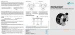
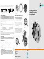
of the rolls (1 K = approx. 2.3 x pitch, 2 K = approx. 3.3 x pitch). The diameter d, must be below the root
diameter of the thread. Also important is the accurate alignment of the head to the component. γ
d1 d2
γ
Operating Instructions
Thread Rolling Heads
FU 5-1, FU 56-1
d1 d2
D
Undercut
Tolerance for the starting diameter:
Once the accurate starting diameter, determined by a test rolling operation, has been found, then this
should be considered as the maximum dimension, if the thread has been rolled just up to its crest and the
effective diameter is approx. at the maximum dimension within the permissible thread tolerance. Among
others the tolerance of the starting diameter is depending to what extent the thread has been rolled to.
As a guide for standard threads with tolerance class 6 g the following may be used: starting diameter
tolerance ≈ half effective diameter tolerance.
Rolling Speed:
According to component profile and spindle speeds available, the following rolling speeds are re-
commended:
for V-type threads approx.
20 – 60 m/min (65 – 200 ft/min)
for Acme-type threads approx.
15 – 30 m/min (50 – 100 ft/min).
The rolling speed is arrived at by figuring the same as tor the cutting speed.
Rolling operation:
The feed rate of approach should be equivalent to the pitch of thread to be rolled. After engagement over
3 – 4 thread pitches, the head itself takes over the feed movement. The support respectively the adaptor
sleeve should be set-up tor easy movement in either direction at any rate.
Fig. 1
Example of Assembly for Rolling Heads in “FU”-design
■■ Separate Parts to be assembled into groups (fig. 1).
Apply ample grease to Ball Bearings to avoid drop
out when putting into the Gear Ring (fig. 2). The gears
on the Gear Sector then point to the centre.
■■ The gears are to be brought into engagement (fig. 3),
attention is to be paid to uniformness and perhaps
marking “0” is to be noted. Gearings to be brought
into approx. centre position.
Fig. 2
■■ Assembly group (fig. 3) to be put on Lower Assembly
Group (fig. 4). The “0” marking has to be in the area
of the Guide Scale. Care should be taken to ensure
that there is no gap within the ball track, because
otherwise the Ball Bearings could drop out.
Coolants and lubricants:
Recommended coolants and lubricants are those, which are also used for cutting operations, i. e. solutions with diluted ratio of 1:10 up to 1:20 – perhaps with high pressure additives – and thin cutting oils.
Possible errors to be made:
1. Starting diameter selected too large or head setting was too small, that means an overload
is generated, which in most cases may be seen at the thread end by building up a bead at the thread crests over approx. the width of the rolls.
2. Chamfering (also at the undercut) is not in line with the rolling instructions.
3. Setting for length selected Incorrect or component length variating (rolls are running against a shoulder).
4. Jamming of the rolls or evidence of wear on the eccentric spindles caused be heavy dirt accumulated in the coolant.
5. Unclean thread start and perhaps damage of the rolls caused by incorrect feed approach.
6. Damage on the Rolls or rolling of two-start threads caused by incorrect assembly of the Rolls.
7. Premature opening of the Rolling Head caused by wear on the Wedges for the Coupling (49) or the Dog Coupling (2). Wedges for the Coupling (49) can be used several times more by turning them around.
Fig. 3
LMT FETTE Werkzeugtechnik GmbH & Co. KG
Grabauer St. 24
21493 Schwarzenbek
Germany
Phone +49 4151 12 - 0
Fax +49 4151 12 - 3797
www.lmt-fette.com
Rolling Head-Hotline +49 4151 12 - 391
E-Mail-Hotline
[email protected]
Fig. 4
Printed in Germany, No. 0000 G (0111 1 DM/DH)
D
γ
www.lmt-fette.com
Spare Parts
IMPORTANT:
In the case of re-ordering of Spare Parts, please state Rolling Head Type and Serial-No.
Please note marking on the Front Plate!
S = Special angle L = Design for Left Hand Threads SL = Special angle for Left Hand Threads X...= Special design Ke = Rolling Head for rolling of Serrations
No.
(example FU 56-1 S)
(example FU 56-1 L)
(example FU 56-1 SL)
(example FU 56-1 X101)
(example FU 56-1 Ke)
In case of re-ordering of Rolls, please state the Roll-Code-No., which is marked on the letter side
of the Roll in addition to the dimension (e. g. for rolling head FU 56-1 e. g. FU 56-1/...)!
27
7a
17
18
8a
52 51
14
26
29
28
42
45
22 33
21
30
38
40
52 51
44
43
3
12 49 39
6
16
48
11
4
37
36
5
19
7
31
25
2
10
46
41
34
9
15
24
8
13
23
Rolling Heads
FU 5-1, FU 56-1
1
53
35
1
2
3
4
5
6
7
7a
8
8a
9
10
11
12
13
14
15
16
172)
18
19
21
22
23
24
25
26
27
28
29
30
31
33
34
35
36
37
383)
391)3)
403)
41
42
431)
44
452)3)
462)
48
49
512)
522)
53
1) for
Pcs.
1
1
1
1
1
3
1
3
1
3
1
3
1
1
4
3
3
1
3
3
145
3
3
3
3
3
6
6
8
6
6
3
3
3
1
1
1
1
3
1
3
2
2
6
1
3
3
3
6
6
3
Description
Flange
Clutch
Operating ring
Spring housing
Gear ring
Gear sectors
Centre plate
Centre plate bushing
Front plate
Front plate bushing
Sleeve
Pin
Coil spring
Brake ring
Spring pin
Eccentric spindles
Spacer studs Bearing cage
Washer
Thread roll
Steel ball
Carbide bushing
Fitting key
Pressure spring Front plate screw
Cap screw
Cap screw
Stud
Cap screw
Hexagon nut
Washer
Lock washer
Shear pins
Roll pins
Stop screw body
Stop screw
Hexagon nut
Ball
Cap screw
Handle
Fitting key
Fitting key
Shear pins
Circlip
Hexagon nut
Set screw
Cover plate
Clutch wedge
Centering ring
Thrust bearings
Set screw
FU 5-1
FU 56-1
3) only for fixed application
2) for
(for fixed and rotating application)
Assembly of Thread RolIs:
Remove Front Plate (8), apply Molykote or similar lubricating agents to the Roll Bearing surfaces if possible. For type FU 56-1: Assemble thrust Bearings (52) together with the Centering Plates (51) and fix
them to both sides of the Rolls. Assemble Rolls in the sequence as marked 1-2-3 or A-B-C in clockwise
direction (for left hand threads in counter-clockwise direction). Insert Needle Roller Bearings (21), put on
Front Plate and screw down tight.
Setting of the Rolling Head to thread diameter:
The Rolling Head has to be set to thread diameter when it is in closed position, that means this is done
by turning the Gear Ring by means of Ball Handle (38) and the Dog Coupling (2) gets into locking position
and there will be a wide gap between Flange (1) and Dog Coupling (2).
The 6 Hexagon Nuts (29) have to be loosened. By using a Setting Gauge, a Thread Sample or a Plain Plug
having the root diameter of the thread to be rolled, the Gear Ring (5) is turned by means of Ball Handle
(38) in such a way until the outside diameter of the Rolls touch in Setting Gauge. After that the Hexagon
Nuts (29) are tightened up in some cases it may be necessary when setting that a slight correction has to
be made on the guide scale towards minus. The accurate setting should be determined by test rolling! If
the effective diameter reached is too big or too small then the head setting has to be corrected towards
minus or plus. A rolled thread should never be overrolled a second time.
Setting of the Rolling Head to thread length:
The thread length is set basically when the Rolling Head is in opened position, to do this it is necessary
that the Operating Ring (3) is pushed towards Flange (1). Between Flange (1) and Dog Coupling (2) there
is now only a very small gap to be noted.
a) Opening by means of Internal End Stop:
Stop Screw (36) is to be set to the required thread length and is locked by Hexagon Nut (37). In doing
this the length of the component extending beyond the clamped portion is of no importance in this
case.
b) Opening by means of External End Stop over Operating Ring:
The thread length is set by an End Stop for use with an additional yoke, keeping the length of component
extending beyond the clamped portion uniform. When the yoke touches the End Stop, the Rolling Head
opens automatically.
Important: As opposed to opening by means of Internal End Stop it is in this case absolutely necessary
to maintain uniform component length extending beyond the clamped portion, in case rolling is done
against a shoulder or similar.
Closing of Head:
In case of fixed application the Rolling Head is closed by means of Ball Handle (38) and turning of the
Gear Ring (5). In case of revolving application closing of the Rolling Head is accomplished by quick brake
action in split second time, this is done by pushing the operating ring by means of the additional yoke
against the Brake Ring (12).
Machining of the component:
Starting diameter d2 to be thread rolled must be equivalent to the effective diameter. Deviations are
possible, depending upon type of component material being used. The starting diameter arrived at now
should never be increased. The components have to be chamfered under) γ = 10° – 25° against the axis
and must be concentric. An undercut at the thread run-out is not required. If an undercut is called for, the
same should be chamfered according to sketch below. The width of the undercut depends upon the lead