1
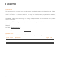
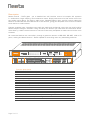
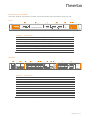
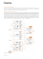
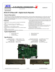
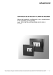
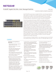
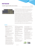
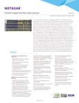
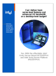
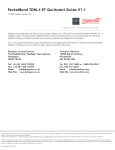
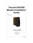
Neets Control - DelTa P/N#: 310-0310 User manual control rx tx input / output RS232 / IR RS485 1 2 3 4 5 6 7 8 9 light control audio mixer level in out 1 2 3 4 5 6 7 8 9 10 11 12 13 14 15 16 zone 1 zone 2 Min Max output 1 chan: 1 2 3 4 5 6 level relay output 2 chan: 1 2 3 4 5 6 level test on Neets Control - DelTa Neets Control - DelTa 1 2 config IR on input 4 input 6 out zone 2 Control: Audio: G=GND L=Left T=TxD R=Right R=RxD G=GND Z=Zone PN: 3 10-0310 www.neets.dk Abbreviations: If unballanced output then use R+ and L+ LL+ G R+ R- If unballanced input then connect R- and L- to G input 2 out zone 1 LL+ G R+ R- LL+ G R+ R- input 5 LL+ G R+ R- input 3 LL+ G R+ R- input 1 L G R LAN LL+ G R+ R- G A B Y Z G T6 T7 T8 G T4 T5 G T2 R2 LAN + uSD Audio RS-485 L G R NEB Half duplex G NCL NDA PWR G T3 R3 RS-232/IR G T1 R1 G 9 10 11 12 G 1 2 3 4 G Z1 I/O 24V/500mA G 13 14 15 16 NO Control COM MAX: 240VAC, 8A 0-10V G 5 6 7 8 MAX: 240VAC, 8A NC NO COM Relay 2 G Z2 110-240VAC 50-60Hz, 8W Relay 1 NC Power Relay made in Denmark Foreword: The purpose of this document is to describe how to install and configure the Neets Control – DelTa. COPYRIGHT - All information contained in this manual is the intellectual property of and copyrighted material of Neets. All rights are reserved. You may not allow any third party access to content, information or data in this manual without Neets’ express written consent. CHANGES - Neets reserve the right to change the specification and functions of this product without any notice. Questions, AFTER reading this manual, can be addressed to your local distributor or: Neets A/S Denmark by E-Mail: [email protected] or you may use our contact form at www.neets.dk Revision list: This document (no: 310-0310-001-007) has the following revision changes: Author: Date TSA: 21-11-13 Page 1 of 11 Description First release. Pages All Rev 1.00 Table of content Foreword: .............................................................................................................................. 1 Revision list: .......................................................................................................................... 1 Table of content ..................................................................................................................... 2 Description: ........................................................................................................................... 3 Connections on DelTa .............................................................................................................. 4 Front: ................................................................................................................................ 4 Backside: ........................................................................................................................... 4 Audio mixer description ........................................................................................................... 5 What is line level on the mixer?: ........................................................................................... 5 Connections ........................................................................................................................... 6 Audio input ......................................................................................................................... 6 Audio output ...................................................................................................................... 6 USB ................................................................................................................................... 6 IR receiver. ......................................................................................................................... 7 Switch and LED .................................................................................................................. 7 Build in relays ..................................................................................................................... 7 0-10 Volt output ................................................................................................................ 7 I/O ports ............................................................................................................................ 7 RS-232/IR ports ................................................................................................................. 8 NEB port............................................................................................................................ 8 RS-485 port ...................................................................................................................... 8 LAN ................................................................................................................................... 9 uSD-Card ........................................................................................................................... 9 Fault finding: .......................................................................................................................... 9 Error LED ........................................................................................................................ 10 Specifications: ..................................................................................................................... 11 Page 2 of 11 Description: Neets Control - DelTa gives you a detailed but still intuitive control of complex AV systems in auditoriums, large meeting -and conference rooms. Simply take control of the entire room from any mobile touch device. The built-in audio-mixer, 240VAC Relays, light- and AV control makes the DelTa an unmatched and cost-effective 3-in-one solution, giving you complete room control via mobile touch device or web browser. Custom graphical user interfaces can easily be made and configured using the new and intuitive Neets Project Designer software. Drag and drop the devices you need from the extensive device driver library, create custom buttons or use one of the many templates to make control of the room a breeze. All connected devices are controlled through a generous amount of RS-232, RS-485, LAN or IR ports, making the Neets Control - DelTa capable of controlling even very demanding facilities. control rx tx input / output RS232 / IR RS485 1 2 3 4 5 6 7 8 9 light control audio mixer level in out 1 2 3 4 5 6 7 8 9 10 11 12 13 14 15 16 zone 1 zone 2 Min Max output 1 chan: 1 2 3 4 5 6 level relay output 2 chan: 1 2 3 4 5 6 level test on Neets Control - DelTa Neets Control - DelTa 1 2 config IR on input 4 input 6 PN: 3 10-0310 www.neets.dk Control: Audio: G=GND L=Left T=TxD R=Right R=RxD G=GND Z=Zone out zone 2 Function description RS-232 (Tx, Rx) / IR (controls up to 2 IR devices on each port) RS-232 (Tx) / IR (controls up to 2 IR devices on each port) LAN device control I/O 0-10V output (Light control) Relays Test buttons NEB Bus (including Extender up to 20m) RS-485 half/full dublex Real time clock IR Learn option with Device editor Unbalanced line in (0dB gain) Microphone input / unbalanced line in (Mic 30-42dB gain) Balanced/unbalanced line in (With up to +12dB gain) Balanced/unbalanced outputs (0dB gain) Mixer line in 0 to -100 dB (induvial volume, treble, bas and balance) Page 3 of 11 Abbreviations: If unballanced output then use R+ and L+ LL+ G R+ R- If unballanced input then connect R- and L- to G input 2 out zone 1 LL+ G R+ R- LL+ G R+ R- input 5 LL+ G R+ R- input 3 LL+ G R+ R- input 1 L G R LAN LL+ G R+ R- G A B Y Z G T6 T7 T8 G T4 T5 G T2 R2 G 13 14 15 16 LAN + uSD Audio RS-485 L G R NEB Half duplex G NCL NDA PWR G T3 R3 RS-232/IR G T1 R1 G 9 10 11 12 G 1 2 3 4 G Z1 I/O 24V/500mA G 5 6 7 8 NO Control COM MAX: 240VAC, 8A 0-10V G Z2 MAX: 240VAC, 8A 110-240VAC 50-60Hz, 8W NC Relay 2 NO COM Relay 1 NC Power Relay made in Denmark 3 5 10 16 2 2 2 1 (5 NEB) 1 Yes Yes 1 1 4 2 All inputs Connections on DelTa There are several connections on back and front please see here bellow what you find. Front: control rx tx input / output RS232 / IR RS485 1 2 3 4 5 6 7 8 9 light control level in out 1 2 3 4 5 6 7 8 9 10 11 12 13 14 15 16 zone 1 zone 2 Min Max audio mixer output 1 chan: 1 2 3 4 5 6 level output 2 chan: 1 2 3 4 5 6 level relay test on Neets Control - DelTa Neets Control - DelTa 1 2 config IR on made in Denmark Number: 1 2 3 4 5 6 7 8 Description Indication for transmitting or receiving on RS-232, RS-485 or IR Indication for input and output on backside (I/O) Light control indication (20% each step) Audio mixer indication (low/med/high level) it is not an VU meter Relay indication and test buttons Mini USB for programming Input for IR learning Power indication input 4 input 6 Control: G=GND T=TxD R=RxD Z=Zone Audio: L=Left R=Right G=GND PN: 310-0310 www.ne ets. dk Abbreviations: If unballanced output then use R+ and L+ LL+ G R+ R- out zone 1 LL+ G R+ R- input 2 If unballanced input then connect R- and L- to G LL+ G R+ R- input 5 LL+ G R+ R- input 3 LL+ G R+ R- input 1 LL+ G R+ R- LAN L G R G A B Y Z G T6 T7 T8 G T4 T5 G T2 R2 G 13 14 15 16 LAN + uSD Audio RS-485 L G R NEB Hal f duplex G NCL NDA PWR G T3 R3 RS-232/IR G T1 R1 G 9 10 11 12 G 1 2 3 4 G Z1 I/O 24V/500mA G 5 6 7 8 NO Number: 1 2 3 4 5 6 7 8 9 10 11 Control COM MAX: 240VAC, 8A 0-10V G Z2 MAX: 240VAC, 8A NC Relay 2 NO COM Relay 110-240VAC 50-60Hz, 8W Relay 1 NC Power Backside: out zone 2 Description 110-230 VAC power in 2 x Potential free relays 2 x 0-10V output connector 16 x Input/output connectors 8 x RS-232 or IR connectors (3 x bidirectional RS-232) 1 x Neets Extension Bus (NEB) 1 x RS-485 Connector 1 x RJ-45 Network (LAN) connector 1 x µSD Card 6 x Audio inputs 2 x Audio outputs Page 4 of 11 Audio mixer description The mixer has 6 channels input and 2 outputs, you can mix all input channels to all outputs. You do also have 12 different treble, bass, balance and loudness function (6 channel in x 2 differential outputs = 12). So this audio mixer gives you flexibility of control. What is line level on the mixer?: Line level is a term used to describe the strength of an audio signal used to transmit analog sound information between audio components such as CD and DVD players, and sometimes MP3 players. In contrast to line level, there are weaker audio signals, such as those from microphones, and stronger signals, as those used to drive headphones and loudspeakers. The strength of the various signals does not necessarily correlate with the output voltage of a device; it also depends on the source's output impedance, or the amount of current available to drive different loads. The most common nominal level for consumer audio equipment is −10 dBV (0,316 VRMS), and the most common nominal level for professional equipment is 4 dBV (1.228 VRMS). When you power up the Neets Control – DelTa for the first time it will be set like this: Page 5 of 11 Input, function Gain settings Output Input 1, unbalanced line in N/A Zone 1 Input 2, unbalanced line in N/A Zone 1 Input 3, balanced line in 0dB Zone 1 Input 4, balanced line in 0dB Zone 1 Input 5, balanced line in 0dB Zone 1 Input 6, balanced line in 0dB Zone 1 Input 1, unbalanced line in N/A Zone 2 Input 2, unbalanced line in N/A Zone 2 Input 3, balanced line in 0dB Zone 2 Input 4, balanced line in 0dB Zone 2 Input 5, balanced line in 0dB Zone 2 Input 6, balanced line in 0dB Zone 2 All balance, treble, bass and loudness will be set to 0dB or off Level -25dB -100dB -100dB -100dB -100dB -100dB -100dB -25dB -100dB -100dB -100dB -100dB (Muted) (Muted) (Muted) (Muted) (Muted) (Muted) (Muted) (Muted) (Muted) (Muted) R+ RR+ R- out zone 2 Channel 2 can be unbalanced line in. Control: G=GND T=TxD R=RxD Z=Zone Audio: L=Left R=Right G=GND PN: 310-0310 www.neets.dk R+ RR+ R- Abbreviations: If unballanced output then use R+ and L+ LL+ G input 6 out zone 1 LL+ G R+ R- R+ R- LL+ G L+ G R+ R- input 4 R+ R- L- L+ G input 2 input 5 LL+ G R L- input 3 R Y Z A B G T6 T7 T8 input 1 L G LAN + uSD Audio RS-485 L G G NCL G NEB Half duplex T3 R3 ND A PWR G 11 12 15 16 T4 T5 9 10 13 14 G G G G T1 R1 3 4 7 8 RS-232/IR G T2 R2 1 2 5 6 G Z1 I/O 24V/500mA G NO Control CO M MAX: 240VAC, 8A 0-10V G MAX: 240VAC, 8A NC NO CO M Relay 2 G Z2 110-240VAC 50-60Hz, 8W Relay 1 NC Power Relay Audio output The output terminal can be used either in balanced or unbalanced mode. Simply use “L-“, “L+”, “R+” and “R-“ for balanced mode,LANand use “L+” and “R+” for unbalanced mode (REMEMBER to NOT connect “L-“ and “R-“) If unballanced input then connect R- and L- to G Channel 3, 4, 5 and 6 can be either balanced line input or unbalanced line input. If you want to use it as unbalanced input you will have to connect the “L-“ and “R-“ to GND in the 5 pin screw block, and connect your signal to “L+” and “R+”. You can in the software set the gain from 0dB to + 6dB if you got a low signal (default is 0dB). out zone 2 USB The USB port (labeled “config” on front) can only be used to configure the control input / output light control audio mixer relay Neets Control – DelTa from the Neets Project Designer software. It cannot be used to control any devices what so ever. The USB port is not able to power the control system while configuring, so always remember to connect the 230 VAC power. The USB connector needed to connect to the Neets Control – DelTa is of the type mini USB B 5P. You can buy this cable on the web (buy a USB A to Mini USB B 5P). rx tx RS232 / IR RS485 1 2 3 4 5 6 7 8 9 level in out 1 2 3 4 5 6 7 8 9 10 11 12 13 14 15 16 zone 1 zone 2 Min Max output 1 chan: 1 2 3 4 5 6 level output 2 chan: 1 2 3 4 5 6 level Neets Control - DelTa Neets Control - DelTa test on 1 2 config IR on made in Denmark Page 6 of 11 Abbreviations: If unballanced output then use R+ and L+ LL+ G out zone 1 LL+ G R+ R- input 6 If unballanced input then connect R- and L- to G R+ R- LL+ G L+ G input 4 R+ R- L- R+ R- input 2 input 5 LL+ G R L+ G input 3 L- Y Z A B G T6 T7 T8 input 1 L G LAN + uSD R RS-485 L G NEB Half duplex G NCL ND A PWR T3 R3 G 11 12 G 9 10 15 16 T4 T5 G 13 14 G T1 R1 3 4 G G 1 2 7 8 RS-232/IR G T2 R2 G 5 6 G Z2 MAX: 240VAC, 8A I/O 24V/500mA G 0-10V G Z1 Control NO NC MAX: 240VAC, 8A 110-240VAC 50-60Hz, 8W CO M Relay 2 NO CO M Relay 1 NC Power Relay Audio input Channel 1 can be either unbalanced line in or a differential dynamic microphone input with 30 – 42dB gain (must be selected in software).LANWhen in microphone mode, left input terminal becomes Cold(-) and right input terminal becomes Hot(+). Audio Connections Control: G=GND T=TxD R=RxD Z=Zone Audio: L=Left R=Right G=GND IR receiver. control input / output light control audio mixer relay The IR learner can be used directly into Neets Device Editor software thru USB cable. You can learn your remote control into the setup software for easy configuration onside, or even on your desk. rx tx RS232 / IR RS485 1 2 3 4 5 6 7 8 9 level in out 1 2 3 4 5 6 7 8 9 10 11 12 13 14 15 16 zone 1 zone 2 Min Max output 1 chan: 1 2 3 4 5 6 level output 2 chan: 1 2 3 4 5 6 level test on Neets Control - DelTa Neets Control - DelTa 1 2 IR config on made in Denmark Switch and LED The 2 switches (SW-1 to SW-2) are used to test the relay functions. The control / output light control audio mixer LED’s is to indicate the if the relay is activatedinputor not. rx tx RS232 / IR RS485 1 2 3 4 5 6 7 8 9 output 1 chan: 1 2 3 4 5 6 level level in out 1 2 3 4 5 6 7 8 9 10 11 12 13 14 15 16 zone 1 zone 2 Min Max relay output 2 chan: 1 2 3 4 5 6 level test on Neets Control - DelTa Neets Control - DelTa 1 2 config IR on 0-10V I/O 24V/500mA G NCL G G 11 12 G NCL G T6 T3 R3 T4 T5 G 9 10 15 16 G G G G T2 R2 G T1 R1 RS-232/IR NEB RS-2 RS-485 When used as input the voltage has to be below 1 Volt DC to be accepted as LOW, and above 4 VDC (but below 24 VDC) to be accepted as high. The inputs are default high and need to be connected to ground in order to change its state, Y Z A B G T6 T7 T8 Half duplex T3 R3 13 14 3 4 G When used as output they are active low (when the software says activated the pin are tied to GND thru a FET transistor also called open drain/collector function). You can draw up to 24VDC/500mA Page 7 of 11 G 1 2 11 12 15 16 G 9 10 13 14 7 8 G G 5 6 3 4 7 8 G G Z1 G Z2 1 2 G 5 6 T4 T5 11 12 15 16 G 9 10 13 14 G T1 R1 G G RS-232/IR G T2 R2 3 4 7 8 G G Z1 G Z2 1 2 5 6 I/O 24V/500mA I/O 24V/500mA ND A PWR NO CO M NC NO Control NO CO M NC CO M NC NO G Z1 MAX: 240VAC, 8A 0-10V G NO CO M MAX: 240VAC, 8A 0-10V MAX: 240VAC, 8A G MAX: 240VAC, 8A NC NO CO M Relay 2 G Z2 110-240VAC 50-60Hz, 8W Relay 1 NC Power Relay I/O ports The Neets Control – DelTa has 16 I/O onboard. They can be used for external keyboard, PIR (movement) sensor, Keyboard lock, extra relays and so on. The ports are not potential free, that means you will need external relays if you need to prevent e.g. ground loops. Relay 2 MAX: 240VAC, 8A Control 110-240VAC 50-60Hz, 8W CO M Relay Power Relay Power Relay 1 The ports are not potential free, that means you will need external protection if you need to prevent e.g. ground loops. Relay 2 MAX: 240VAC, 8A 110-240VAC 50-60Hz, 8W 0-10 Volt output The Neets Control – DelTa has 2 0-10Volt output. They can be used for controlling e.g. light or level on external equipment. Relay 1 NC Build in relays On Relays there is access to both the NO (Normal open contacts) and the NC (Normal close contacts) for greater flexibility. Control made in Denmark NEB RS-485 LAN + uSD LAN Y Z A B G T6 T7 T8 G T4 T5 G G T2 R2 Half duplex ND A PWR G NCL T3 R3 G G T1 R1 11 12 9 10 G 3 4 1 2 RS-232/IR 15 16 13 14 G 7 8 G G Z1 I/O 24V/500mA G G Z2 MAX: 240VAC, 8A 0-10V 5 6 NO Control NC MAX: 240VAC, 8A 110-240VAC 50-60Hz, 8W CO M Relay 2 NO CO M Relay 1 NC Power Relay RS-232/IR ports The onboard RS-232 ports (T1, R1, T2, R2, T3, R3, T4, T5, T6, T7 and T8) is used for one or two way communication (port 1-3 is two way, 4-8 is one way). This port is used for the device you want to use reply on (e.g. your projector). The DelTa can on all RS-232/IR ports has 4 ports (T2, T3, T4 and T5) that can be configured (in software) either as RS-232 or as IR emitter. IR 2 emitter L- L+ R L- L+ L G input 2 out zone 2 input R input 1 L G Half duplex T=TxD R=Right R=RxD G=GND Z=Zone PN: 310-0310 www.neets.dk If unballanced output then use R+ and L+ R+ R- LL+ G Control: Audio: G=GND L=Left LAN G LA L+ B G Y R+ Z R- LG LNCL + G ND A R+ PW R R- NEB RS-485 input LAN + uSD LAN Y Z A B G T6 T7 T8 G T4 T5 G Half duplex ND A PWR G NCL T3 R3 G G T1 R1 RS-232/IR G T2 R2 G 9 10 13 14 G 3 4 7 8 1 2 5 6 G I/O 24V/500mA G G Z1 Control NO MAX: 240VAC, 8A 0-10V G Z2 MAX: 240VAC, 8A CO M NC NO CO M Relay NC Power 110-240VAC 50-60Hz, 8W Relay 2 input 6 RS-485 uSD out zone 1 LAN +Abbreviations: When used as dual IR port: Connect the IR 1 emitter to e.g. T1 (white striped wire) and black wire on IR 1 emitter to IR 2 emitter (white striped wire), and black wire from IR 2 emitter to GND, as shown here above. NEB port The Neets Control – DelTa has a build in NEB (Neets Extension Bus). This port is used to add up to 5 NEB devices (2 Keyboard, 2 Level Control and one Expander). The NEB port have build in NEB extender that give you up to 20m from the DelTa to your NEB devices. BUT you MUST connect NEB extender module (310-0005) in the end for you NEB units Relay 1 NEB If unballanced input then connect R- and L- to G input 4 input 5 GLL+ T6 G T7 R+ T8 R- input 2 L+ R2 G G R+ T4 RT5 R G LT1 LR1 + G G R+ T3 RR3 R G LT2 11 L1 2 G 10 Audio 15 16 L G 13 14 3 4 PN: 310-0310 G www.neets.dk 9 G input 1RS-232/IR input 3 11 12 When used as single IR port: Connect the IR emitter to e.g. T1 (white striped wire) and GND, as shown here above. 7 8 1 2 5 6 G G If unballanced output Control R+ R- NO LL+ G duplex COM Half NC MAX: 240VAC,out 8Azone 2 240VAC, 8A input 6 G then use R+ and L+ G Z2 Z1 MAX: G LA L+ B G Y R+ Z R- R+ PWR R- NO COM R+ T8 R- NC LG L+ NCL G NDA Relay 8W input50-60Hz, 2 input 4 2out zone 1 LAN 0-10V I/O 24V/500mA NEB Relay RS-485 +Abbreviations: uSD Control: Audio: G=GND L=Left LAN T=TxD R=Right R=RxD G=GND Z=Zone If unballanced input then connect R- and L- to G Relay input 5 1 GLL+ T6 G T7 G R G LT1 L+ R1 G G R+ T3 RR3 R G LT2 L+ R2 G G R+ T4 RT5 110-240VAC 15 16 L G 9 10 Audio 11 Power 1 L2 G G 7 8 5 6 input 1RS-232/IR input 3 15 16 When used as RS-232 transmit port: Connect the device to e.g. T1, R1 and GND, as shown here above. G LAN 13 14 3 4 1 2 G G Z1 Control LAN + uSD 0-10V I/O 24V/500mA G Z2 duplex CO M Half NC NO Y Z A B MAX: 240VAC, 8A G G NCL NDA PWR NO CO M NC T3 Relay 2 MAX: 240VAC, 8A T6 T7 T8 G R3 Relay T4 T5 G 110-240VAC 50-60Hz, 8W Relay 1 G G T1 R1 RS-232/IR G T2 R2 9 10 G 3 4 1 2 L- L+ L- L+ input R Y Z A B T6 T7 T8 G T4 T5 G Page 8 of 11 input 1 R LAN L G LAN + uSD L G RS-485 Audio NEB Half duplex ND A PWR G NCL G G G T1 R1 RS-232/IR G T2 R2 11 12 15 16 9 10 13 14 3 4 G G 7 8 5 6 1 2 I/O 24V/500mA G G Z1 Control NO CO M MAX: 240VAC, 8A 0-10V G MAX: 240VAC, 8A NC NO CO M Relay 2 G Z2 110-240VAC 50-60Hz, 8W Relay 1 NC Relay RS-485 port The onboard RS-485 ports can either run in full duplex (using all 5 wires) or in half duplex (using 3 wires). From the Project Designer you can set the different modes, you can also swap RxD wire or TxD wire, if you get the wire wrong monuted T3 R3 The DelTa have built in NEB Extender, so you need extender for all your NEB units Power G 11 Power 12 15 16 13 14 G 7 8 5 6 G Z1 I/O 24V/500mA G 0-10V G Z2 NO MAX: 240VAC, 8A Control CO M NC elay 2 Audio IR 1 emitter IR emitter PIN 2 to RX PIN 3 to TX PIN 5 to GND NEB RS-485 input 2 input R+ R- R+ L+ G R+ R- LL+ G L- L+ G input 4 R+ R L- input 2 input 5 LL+ G L G Y Z input 3 R LAN Half duplex G input 1 Audio LAN + uSD L G RS-485 A B ND A PWR G NCL T3 R3 G NEB T6 T7 T8 G T4 T5 G G T1 R1 RS-232/IR G T2 R2 9 10 G 3 4 1 2 G 11 12 15 16 13 14 G 7 8 G Z1 I/O 24V/500mA 5 6 NO Control MAX: 240VAC, 8A 0-10V G MAX: 240VAC, 8A CO M NC NO CO M Relay 2 G Z2 110-240VAC 50-60Hz, 8W Relay 1 NC Power Relay LAN The network connector is for connecting the system to the local area network. input 6 There are two LED’s on the connector. They have the following meaning: Color: Yellow Green Off No Link 10Mbit On Link 100Mbit Blink Activity Default IP settings is: Fault finding: On front of the unit you will find 5 LED used for error indication (on LED and input/output LED 1-4). The on LED can have the following indications: Description System starting System running System in error Firmware upgrade in progress Page 9 of 11 “on” LED behavior Orange color non flashing White color non flashing Red color blinking Orange color non flashing LL+ out LL+ input 6 If unballanced input then connect R- and L- to G R+ R- R+ R- REMEMBER to remove power from unit before removing Micro SD card! R+ R- L+ G R+ R- input 4 LL+ G L- input 2 input 5 LL+ G R input 3 L+ G input 1 L G LAN Y Z A B G T6 T7 T8 G T4 T5 G G T2 R2 15 16 13 14 G 7 8 5 6 MAX: 240VAC, 8A G MAX: 240VAC, 8A G Z2 To remove the SD Card from the unit, you push the SD Card GENTLY into the holder about 1mm (by using your finger tip). Release again, and it will slide out. 110-240VAC 50-60Hz, 8W LAN + uSD L- RS-485 R NEB Half duplex ND A PWR G NCL T3 R3 G RS-232/IR G T1 R1 11 12 9 10 G 3 4 1 2 I/O 24V/500mA G 0-10V G Z1 Control NO CO M NC Relay 2 NO CO M Relay 1 NC Power Relay uSD-Card The uSD-Card is used to storage firmware, homepage and settings. Under normal operation removal of the uSD-Card is not needed. Audio 192.168.254.253 255.255.255.0 Auto Disabled L G IP address: Subnet: 10/100Mbit: DHCP: out Error LED If system in Error the on LED on front is flashing reed together with some of the input/output LED. The fault type and solution for it you can find here bellow… LED shows Description No connection to one or more NEB units. No project found on the control system Solution Check that the NEB units used in the project are connected. Make sure that there are used a NEB extender at the NEB unit end. If you are using long cable try to add a power at the NEB units. After doing one of the above thing remove the power to the control system for 20 sec before reconnecting the power again. Try to upload the project again. If the problem keep appearing after several successfully upload. Contact Neets or your local distributor. Missing SD card or error on SD card Unexpected Error Make sure that there is a SD card inserted in the Control system. (Look at the back side) After doing one of the above thing remove the power to the control system for 20 sec before reconnecting the power again. Remove the power to the control system for 20 sec before reconnecting the power again. If the error keep coming. Contact Neets or your local distributor. Page 10 of 11 Specifications: Power input Voltage Frequency Power usage Connector type Relay output Voltage max Current max Load max AC1 Load max AC15 Single phase motor Connector Network (LAN) 97VAC - 240VAC 47Hz - 63Hz 8W IEC plug 240VAC 8A 1150W @ 230VAC 500W @ 230VAC 370W @ 230VAC 3 pin screw block 0-10V output Output error Min step (full scale) Mode options Output impedance Output current max Connector +/- 0.01% full scale 2048 0-10V, 1-10V, free 10R 25 mA / 400 ohm 2 pin screw block Input / Output Input trigger low Input trigger high Output type Isolated output Max voltage load Max current Connector RS-232 Baud rate Data bits Parity Stop bits RS-485 Duplex modes Baud rate Data bits Parity Stop bits IR Transmit frequency IR Learn frequency Page 11 of 11 > 1VDC < 4VDC Open drain No 24VDC 0.5A 5 pin screw block 1200-115200bit/sec 7–8 Even, Odd, None 1/2 Half or full 1200-115200bit/sec 7–8 Even, Odd, None 1/2 400Hz to 500 KHz 1KHz to 150 KHz Speed Duplex modes DHCP Default IP Default gateway Default subnet mask 10/100Mbit Half or full Default off 192.168.254.252 192.168.1.1 255.255.255.0 Audio Un- or Balanced inputs Microphone or line input Unbalanced input Un- or Balanced outputs Microphone gain Mic SNR (@3,6mV RMS) Line in SNR (@ 1V RMS) Channel separation Frequency response Input level max (THD 1%) Output max (THD 1%) Balanced input Gain Volume level Mute 4 1 1 2 30dB - 42dB <93dB <92dB <95dB 20Hz - 20KHz +/-1dB 2.3VRMS 2.3VRMS 0 - 6dB 0 - -79dB <100dB uSD-Card Type Card size min / max size File system Micro-SD, 1Gb / 4Gb FAT 32 General With (mm) Depth (mm) High (mm) Weight kg/lbs Weight shipping kg/lbs Dimension shipping (W/D/H) Storage temperature Storage moisture Operation temperature Operation moisture 437 / 483mm. 141mm. 44mm. (1U) 1.9kg / 4.1lbs 2.2kg / 4.9lbs 530mm / 230mm / 80mm -20°C to 50°C Non condensing 0°C to 30°C Non condensing