1
LWA TV on the Raspberry Pi
Whitham D. Reeve
1. Introduction
Abbreviations
DHCP: Dynamic Host Configuration Protocol
DVI: Digital Visual Interface
GUI: Graphical User Interface
HDMI: High Definition Media Interface
IP: Internet Protocol
LAN: Local Area Network
LWA: Long Wavelength Array
RPi: Raspberry Pi
UNM: University of New Mexico
VGA: Video Graphics Array
This article describes how to use the tiny and inexpensive Raspberry Pi
computer with the Long Wavelength Array in New Mexico to observe
celestial radio sources in near-real-time (LWA1, figure 1). The
application was developed by the University of New Mexico (UNM) as
part of LWA Education and Public Outreach. It is a good way to become familiar with the LWA, LWA TV and the
Raspberry Pi, all at the same time. The LWA TV program does not allow user control, only observation, and it
runs “out of the box” with no user programming whatsoever.
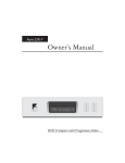
Figure 1 ~ The Long Wavelength Array in New Mexico consists of a forest of 257 crossed-dipole, tied-fork antennas. Beams
are formed through signal processing to observe specific celestial radio sources or areas of the sky. (Image © 2014 W.
Reeve)
One of the advantages of the approach described here is that no hardware construction or software
programming is required – off-the-shelf hardware and software is all that is needed. Another advantage is that
See last page for copyright and document information, File: Reeve_RPi-LWATV.doc, Page 1
the software for the LWA TV graphical user interface (GUI) is prepackaged by UNM and available for free. When
I started working on this project (August 2014) UNM’s software worked only with the Raspberry model B. I
contacted Jayce Dowell at UNM and he updated the software to run on both the model B and B+ (the B+ is the
latest Raspberry Pi hardware version). Although the LWA TV software is plug-and-play, there is room for some
customization, which I describe in section 5.
I started writing this article to answer most of the questions that might arise while setting up the LWA TV
application and ended up writing a reference manual. The first half provides general descriptive information and
the second half contains setup details.
2. Long Wavelength Array
The LWA is used to study celestial objects or areas of the radio sky in the
Note: Internet links in braces { }
and references in brackets [ ]
frequency range 10 to 90 MHz {LWA}. Its primary purpose is scientific but
are provided in section 6.
education and public outreach are important parts of its government-funded
mission. One of the features of the LWA website is LWA TV {LWA TV} – a near real-time visual representation of
the data produced by the array (figure 2).
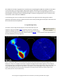
Figure 2 ~ Image from LWA TV as seen on the internet. The two circles represent the sky seen by the LWA at radio
frequencies, in this case, 37.80 MHz. The horizon is along the circle edges and the zenith (straight up) is in the middle of
each image. Dark blue is the background and brighter areas (in order of increasing radio intensity – blue, green, yellow, red)
are the Milky Way galaxy and spots are radio sources. The locations of some of the brighter celestial radio sources are
labeled. The images show total intensity (left) and intensity of circularly polarized radio waves (right). (Image source:
http://www.phys.unm.edu/~lwa/lwatv.html)
See last page for copyright and document information, File: Reeve_RPi-LWATV.doc, Page 2
Although LWA TV can be watched in near real-time on any PC with internet access, observers may want to setup
a dedicated monitor for LWA TV and then use the PC with their own radio telescope. For example, one could
observe Jupiter or the Sun with their own radio telescope using Radio-SkyPipe (RSP) or Radio-Sky Spectrograph
(RSS) while watching for activity on LWA TV. This allows confirmation or correlation of observations. Of course,
the radio sources would need to be in common view of the LWA and the observer’s radio telescope. Another
application is radio astronomy club outreach. The setup could be used at meetings, conventions and
conferences. It should be noted that LWA TV itself does not allow real-time access to the actual data nor does it
store any of the individual real-time images.
3. Raspberry Pi
The Raspberry Pi (abbreviated RPi throughout this article) is a small computer platform designed for educational
purposes by the Raspberry Pi Foundation {RPi}. The RPi is low cost, about 35 USD (40 USD with memory card),
and has HDMI video, Ethernet LAN and USB interfaces (figure 3). It is euphemistically advertised as “credit-card
size” but actually is much larger. It can be plugged into an ordinary computer monitor or TV and can use a WiFi
wireless access device for LAN and internet access and wireless or wired USB keyboard and mouse.
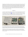
Figure 3 ~ Raspberry Pi model B and B+ hardware. The model B+ is shown in the middle with an optional clear plastic
enclosure. The model B on the left is in an optional milled aluminum enclosure and is shown with a Bluetooth USB dongle.
The model B on the right is in a molded clear plastic enclosure and rotated to show the opposite end. The interfaces vary
slightly between the model B and B+. Enclosure dimensions are approximately 100 x 65 x 25 mm. (Image © 2014 W. Reeve)
The RPi hardware usually runs an operating system derived from Linux and (as of this writing) has become
available in three versions – original model A model (not generally available in North America), model B and
model B+. The model B and B+ are compared (table 1). For the LWA TV application, there is no advantage of one
over the other model.
See last page for copyright and document information, File: Reeve_RPi-LWATV.doc, Page 3
I have not tried the RPi model A, and I initially could not get the LWA TV software image provided by UNM to
work on the RPi B+. I was successful only with the RPi B. All the information available from the Raspberry Pi
Foundation for the model B+ insists that it is software compatible with the model B but I found there were
problems that affected the LWA TV GUI. These were resolved in September 2014 and the software image now
available from UNM works fine on both the B and B+.
Table 1 ~ Comparison of Raspberry Pi Model B and B+ Hardware
Description
RPi B
RPi B+
RAM
512 MB
512 MB
Memory card
SD
micro-SD
Processor system
BCM2835 SOC
BCM2835 SOC
Video 1 connector
Standard HDMI
Standard HDMI
Video 2 connector
RCA Composite
3.5 mm audio + Composite
Audio connector
3.5 mm
see Video 2
USB connector
2
4
Power connector
micro-USB
micro-USB
GPIO connector
26 pin
40 pin
Network connector 10/100 Ethernet
10/100 Ethernet
Power
5 V, ~5 W
5 V, ~3 W
Dimensions
85 x 56 x 21 mm
85 x 56 x 21 mm
Mounting
2 holes
4 holes
Cost
35 USD
35 USD
Hardware: The Raspberry Pi can be purchased from any number of suppliers worldwide. It is necessary to add a
Secure Digital (SD) to the model B or micro-SD memory card to the model B+ for the LWA TV software image.
Sometimes the vendor supplies a card with the RPi purchase. A card with 8 GB minimum capacity is
recommended but 4 GB is sufficient. Also, an HDMI monitor is needed. A VGA monitor may be used if an HDMIto-VGA converter (figure 4) is connected between RPi and the monitor. A keyboard with or without a mouse
might be handy but is not necessary. No changes are required to the RPi platform but it should be installed in an
enclosure. A Secure SHell (SSH) terminal generally is used to communicate and manage RPi from another
computer on the same network. This is described in more detail in section 5.
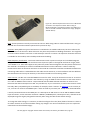
Figure 4 ~ HDMI-to-VGA converter allows the RPi to be used with most
computer monitors. The ones shown here cost about 10 USD. The RPi
requires a full-size HDMI connector seen on the left converter. An
adapter will be needed If the converter has a mini-HDMI connector as
seen on the right converter. (Image © 2014 W. Reeve)
The power requirements of the RPi are modest, about 5 W for the model B and 3 W for the B+ assuming no
current is being drawn from the USB ports. Because these powers are more than supplied by a standard USB
port on a PC it is necessary to use an external power supply or power adapter. If no USB peripherals are used,
the RPi can be powered by a well-regulated, low ripple, electrically quiet power source rated ≥ 1.0 A at 5.0 Vdc
See last page for copyright and document information, File: Reeve_RPi-LWATV.doc, Page 4
(≥ 5 W). If the RPi USB ports are to supply power to peripherals, then a 10 W or higher power source should be
used. Using a poor quality power supply will lead to unreliable operation so be sure it meets these
requirements. One of the most common problems users have with the RPi is inadequate power supply current.
To minimize electrical noise, it is recommended that ferrite beads be installed on the power cable (figure 5).
Figure 5 ~ AC wall power adapter with 5 V, 2.4 A (12 W) output
purchased at BestBuy. One or more clamshell ferrite beads on the dc
power lead help reduce radio frequency interference from the switchmode power supply. This image shows one bead on the right with three
windings of the power lead. The Raspberry Pi uses a micro-USB
connector for power. (Image © 2014 W. Reeve)
Software: The RPi uses a software image that includes the operating system and applications. The RPi image
developed by UNM for the LWA TV GUI is based on a Raspbian distribution. The software must be user-installed
on a memory card. Installation is not difficult but it is done in a way that is not obvious to most Windows PC
users. UNM provides links to web pages with the necessary procedures (see {LWA EPO}). These procedures also
are briefly listed in the Software installation part of section 5. To make this process a little simpler, I can provide
a preprogrammed micro-SD card in an SD card carrier to interested readers. See Contact information at the end
of this article. With this memory card, the system truly is plug-and-play.
When running the LWA TV GUI software, the RPi can be used only for that purpose. However, the software is
written in Python and may be modified by users if they feel “adventurous”. Python is an interpreted language
and, therefore, is not compiled so nothing more than a text editor is needed to write or modify an application.
Notepad++ is perfect for this purpose and is free {Notepad++}, but Windows Notepad will also work. The
advantage of Notepad++ is that it automatically formats and indents the code to make it easier to read and work
with.
The main piece of software in the LWA RV GUI is lwaTV3rpi.py, about 16.5 kB of text. Examining the code shows
that it includes four command line switches, or options, which may be used to customize the GUI. The program
operates normally with its default settings, and there is no compelling reason to change them except for
experimental purposes. Using these options requires knowledge of the operating system and I will not discuss
them further.
4. LWA TV on Raspberry Pi
The setup for LWA TV is very simple (figure 6). By default the LWA TV GUI uses the wired network interface
(Ethernet) built into the RPi and acquires a network (IP) address automatically using dynamic host configuration
protocol (DHCP). You can change this to a static IP address and add a WiFi interface. However, to eliminate many
See last page for copyright and document information, File: Reeve_RPi-LWATV.doc, Page 5
potential problems, I recommend first running the LWA TV GUI in its default configuration to become familiar
with it before making any changes. See section 5 for some changes that you might find useful.
With the programmed memory card installed, make all connections before applying power to the RPi: (1) HDMI
connection to your monitor or television set (be sure it is turned on); (2) Ethernet connection to your internet
router; and (3) micro-USB connection to an ac power adapter. When power is applied, the RPi system
automatically starts and the display will show lines of text that scroll by rather quickly. Upon completion of the
boot up process, the display will momentarily blank and then the LWA TV GUI will appear. The LWA TV GUI
shows the real-time images plus archived movies (figure 7). If the program is running but does not have a proper
network connection, you will see “Error Downloading Image” and “Network Connection Error” on the display
(figure 8). An archived movie may be running but the live portion of the display will be gray. The LWA TV GUI
connects within a second or two after the network connection is established. I did not have to make any
changes in my internet router for LWA TV, but if you have network connection problems your router and its
firewall are the first place to start troubleshooting (after checking that the cable is plugged in).
If everything seems to be working okay it is a good idea to update both the software and the archived movies
upon first use. Log into the RPi console as discussed in the RPi console part of section 5 and execute the
commands given in the Update part.
Memory
HDMI
or VGA
Monitor
Monitor
or TV
Video
Raspberry Pi
Model B or B+
Power
AC Power
Adapter
Long
Wavelength
Array
Station 1
New Mexico
Network
Internet
Minimum equipment list:
Raspberry Pi B or B+
Power supply
HDMI cable
4 GB memory card
Monitor or TV
Ethernet cable
USB Keyboard/mouse
Optional:
WiFi device
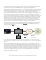
Figure 6 ~ Block diagram and equipment list for the RPi when setup for LWA TV. See text for description of each item.
Before applying power to the RPi make all connections and turn on power to the monitor or television set. (Image © 2014
W. Reeve)
When connected, LWA TV downloads a daily average of approximately 25 kB/s, 91 MB/h or 2.2 GB/d. The
internet traffic is split between the real-time images and archived movies. The LWA station processes the data
and prepares images in near real-time. The LWA TV GUI checks for and downloads a new image every 5 s. Each
image includes the total radio energy received during the 5 s interval, so transient emissions lasting less than 5 s
are recorded. The images are about 120 kB each so the average network traffic load is about 24 kB/s. The
archived movies are downloaded in the evening and are usually around 100 MB each. Downloading uses
whatever internet bandwidth is available.
See last page for copyright and document information, File: Reeve_RPi-LWATV.doc, Page 6
If your internet service has download limits and imposes penalties when exceeded, it would be wise to monitor
your usage closely. If you want to reduce the internet usage overnight or other times, you can simply unplug the
Ethernet cable rather than shutting down the RPi. If you use a wireless network connection, you will need to use
a software method to stop network usage. The LWA TV application updates the movie archive cache at 1830 in
the time zone used by the RPi. By default, the LWA TV software uses mountain daylight time (MDT) but both the
time zone and movie cache update time can be changed. See Date, time and time zone in section 5 for these
and a method to suspend the software at night or outside normal observation times to reduce network usage.
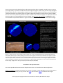
Figure 7 ~ LWA TV screen. The live image at top-left shows one or two circles depending on the current LWA operating
mode. When LWA is setup for beam pointing, only one circle may appear as shown here; otherwise, two appear. The two
circles at bottom-middle are archive movies from the previous several days. The movies cover a full day, often with gaps,
and each requires about 12 minutes to run. Sometimes radio frequency interference is seen along the edges of the circles.
The aerial image of the LWA at lower-left is fixed and text on right changes depending on normal or beam-pointing view of
the live image. (Image source: http://fornax.phys.unm.edu/lwa/trac/wiki/EPO)
5. Installation and Operation Notes
This section provides information that will help first-time users. It is focused on the LWA TV application.
Software installation: The brief instructions here assume the reader is using a Windows PC to install the LWA TV
GUI software on the memory card: (1) Install 7-Zip {7-Zip}, SD Formatter {SDFmt} and Win32 Disk Imager
See last page for copyright and document information, File: Reeve_RPi-LWATV.doc, Page 7
{WDImg} on the Windows PC. When running the latter two programs, run them as Administrator; (2) Put the
memory card in a card reader (see Note below) connected to the PC and use SD Formatter to format the card. In
SD Formatter set the Options to Format Type = Full Erase and Format Size Adjustment = On; (3) Download the
LWA TV GUI software image for the RPi from {LWASoft}. The file is compressed so decompress it with 7-Zip to a
raw image file (*.img). This will take a few minutes; (4) Write the software image to the memory card with
Win32 Disk Imager using its default settings. This will take a few minutes. After the Write operation is finished,
the memory card is ready to use in the RPi. Be sure RPi power is OFF and insert the card. Note: Some micro-SD
cards and card readers are incompatible, so it is best to install the micro-SD card in a full-size SD card carrier,
insert the carrier into the reader and then format the card and load the software image.
Figure 8 ~ If there is a network connection
problem, the live globes are gray and warnings
appear. During normal operation, the Error
Downloading Image message may momentarily
appear but it is nothing to worry about if it
happens only occasionally. (Image © 2014 W.
Reeve)
The RPi model B uses an ordinary push-to-insert/pull-to-release slot connector whereas the model B+ uses a
push-to-insert/push-to-release slot connector. When the RPi is powered ON, the software will load and run
automatically.
RPi console: In order to make changes to the RPi setup (described later in this section), it is necessary to log into
the RPi console. This may be done from a Windows PC that is on the same network as the RPi. or through a
wireless or wired keyboard. The RPi uses secure shell (SSH) for console communications so it is necessary to
install an SSH client application such as {PuTTY} or {TeraTerm} on your PC if using the network connection.
To use SSH, first determine the IP address assigned to the RPi by your internet router. Procedures vary widely
and it is best to read your router user manual or search for online help. The RPi host name is “lwatvgui” (without
quotes) and will be identified as such in your router’s local network status screen. An alternate, and perhaps
quicker, method is to download and install on a Windows PC a network scan program as described at {RPiNet}.
For PuTTY place the RPi IP address into the Host Name or IP address field and click Open (figure 9). After
authentication you will see the RPi login prompt. The default username is“pi” (without quotes). After you enter
the username, RPi will ask for the password. For obvious reasons I will not publish the password here, but it can
be obtained by emailing the address given at the very bottom of {LWA EPO}.
Updates: To update the LWA TV software and archived movie cache, send the following commands one at a
time using the SSH terminal described above. Wait for each process to complete before entering the next
command. It is necessary to send these commands only upon first use of the LWA TV GUI image:
See last page for copyright and document information, File: Reeve_RPi-LWATV.doc, Page 8
cd ~/LWATV/
svn update
./updateMovies.py -v
sudo rpi-update
sudo reboot
It is a good idea to routinely update the Raspbian software distribution as well. Send the following commands
with an SSH terminal to update the non-LWA TV software (these updates and upgrades can require tens of
minutes if new distributions have become available after the last update):
sudo apt-get update
sudo apt-get upgrade
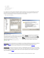
Figure 9 ~ Upper-left: Screenshot of PuTTY configuration
window with the IP address for one of my setups. Upperright: Upon first connection, PuTTY asks for authentication.
Lower-left: When PuTTY is connected, the window changes
to a simple command line interface. After login, you can
make changes to the RPi. (Images © 2014 W. Reeve)
Documentation: Online documentation for the Raspberry Pi including troubleshooting information is available at
{RPiDoc} and {RPiHub}. There also are numerous forums that have information related to RPi. The only
documentation that exists for the LWA TV application is this article and information at {LWA EPO}.
Keyboard-mouse: The LWA TV GUI has built-in drivers for a USB keyboard and mouse but they are not required
for normal operation. However, a keyboard is nice to have if you need to directly access the RPi or cannot access
it indirectly using SSH as described above. Small wired or wireless keyboards, with or without a mouse (figure
10), are available from {Adafruit}.
See last page for copyright and document information, File: Reeve_RPi-LWATV.doc, Page 9
Figure 10 ~.Wireless keyboard and mouse uses a Bluetooth
connection. The keyboard is about 285 mm long. A
Bluetooth dongle is included and requires one USB port as
seen on the left of the RPi model B in the image. (Image ©
2014 W. Reeve)
Heat: The RPi processor normally runs warm but not hot. While using LWA TV I measured about 30 °C using an
infrared non-contact thermometer pointed at the processor chip.
Enclosure: Many different types of enclosures are available for the model B and B+ RPi, but the enclosures for
one model do not fit the other. Most enclosures are plastic and provide no shielding whatsoever. This might be
of concern where the RPi is used near a radio telescope antenna or receiver. An expensive aluminum enclosure
is available for the model B, and it should provide better shielding.
Radio frequency interference: I took some measurements with a spectrum analyzer and a shielded magnetic
loop probe and electric field probe and found several spectral spikes in the high MF and low HF ranges, about
1.5 to 8 MHz or so. These were apparent only when the probes were held against the clear plastic enclosure of
the model B+. I checked up to several hundred MHz but found no other indications. I did not make any
measurements with the aluminum enclosure on the model B. It should be noted that conducted interference in
connecting cables often is radiated because the cables act like antennas, so each installation will have different
RFI characteristics and it may be necessary to install ferrite beads on all connecting cables.
Video monitor: The RPi uses a standard HDMi connector for video. It may be used with a monitor or TV with an
HDMI input. It also may be used with a VGA monitor by using an HDMI-to-VGA converter or with a DVI monitor
or TV with an HDMI-to-DVI converter. I experimented with the HDMI and VGA interfaces on monitors and
televisions but did not attempt to use DVI. For portable use, say at a convention, a small screen monitor would
be handy. Many compatible types are available; for example, search “monitor” at {Adafruit} to see a variety of
5.6, 7 and 10.1 in monitors with HDMI inputs. I have not tried any monitors/TVs except those discussed below.
I initially connected the RPi to the HDMI port on a Hannspree HF-199 monitor. The HF-199 has HDMI and VGA
input connectors, and its maximum resolution is WXGA+ (1440x900 pixels, 16:10 aspect ratio). I found that the
displayed image was slightly elongated horizontally when using the LWA TV GUI default settings.
To change the video settings, it is necessary to edit the config.txt file in the /boot/ folder of the RPi. It is best to
do a little research on the internet before making any changes. Use nano to edit the file (nano is a simple text
editor built-into the software image):
See last page for copyright and document information, File: Reeve_RPi-LWATV.doc, Page 10
sudo nano /boot/config.txt
After making the desired changes and saving the file, reboot the RPi:
sudo reboot
I tried changing the RPi video settings to different screen resolutions and eventually found that only one HDMI
mode provided a better display and that was at the monitor’s maximum resolution 1440x900 (hdmi_group=2,
hdmi_mode=47). However, at this high resolution, the real-time display and archive movies sometimes would
momentarily stall or skip.
I then tried an HDMI-to-VGA converter on the monitor’s VGA input and could not obtain a good display. With
many settings I had no display at all. I spent about one full day trying different port settings on the monitor and
RPi. I finally gave up and settled on using only the monitor’s HDMI port. This monitor works very well at
1440x900 pixel resolution with the VGA interface on the lab PC.
I also tried our Philips 47 in LCD television set. This TV has three HDMI ports and supports several resolutions,
480p, 720p, 1080p and 1080i. I found I could obtain a nice picture using RPi settings for 720p (hdmi_group=1,
hdmi_mode=4) and overscan (overscan_right=40, overscan_left=40, overscan_top=16, overscan_bottom=16)
(figure 11). Although this TV supports 1080p and 1080i, I could not find any RPi overscan settings that provided a
properly positioned horizontal display. Based on my experience so far, I think the video interface
implementation is the RPi’s biggest shortcoming (the video implementation is separate from the LWA TV GUI).
Perhaps with enough time and experimentation, I could make it work better at different resolutions.
See last page for copyright and document information, File: Reeve_RPi-LWATV.doc, Page 11
Figure 11 ~ Philips 47 in LCD television set connected through one of its HDMI ports to the RPi. The RPi HDMI port was set
for 720p resolution (see text). (Image © 2014 W. Reeve)
As a final video test, I connected a Dynex 19 in LED-LCD TV that I use in the lab. This is a small set designed as a
kitchen counter TV with a wide range of video inputs. After using the TV menu to select the HDMI port, the
screen immediately showed the correct display. I made no changes in the RPi video settings (720p) used with
the 47 in TV previously described.
Date, time and time zone: By default, the Raspbian distribution uses Network Time Protocol (NTP) to
automatically set the RPi time when it is connected to the internet. The RPi does not have a real-time clock or
battery backup, so it must be running and connected to the internet to correctly set time and date. To confirm
the date, time and time zone, enter the following at the RPi prompt on the SSH terminal:
date
To change the time zone, enter the following. The displayed instructions will lead you through the
reconfiguration:
sudo dpkg-reconfigure tzdata
To confirm the scheduled download time for the daily LWA TV movie archive update, enter the following to see
what is in the cron table (cron is a utility that runs automatically in the background at specified times):
crontab –l
You should see a number of comments with the last two lines as follows:
# m h dom mon dow
command
30 18 * * * python ~pi/LWATV/updateMovies.py
The last line is the scheduled event with a time of 1830 in the system time zone. It is shown in crontab with
minutes before the hour. To change the scheduled time, enter the following to edit the cron table. This will
invoke the default editor and allow you to change the time in the table. Do not change anything on the last line
except the minutes and hour:
crontab –e
The crontab function also can be used to temporarily stop and then restart the LWA TV application software at
regular intervals to reduce network usage. For example, you could use a stop process at a specified time, say
2200 in the evening, and then a start process the next morning at 0700. The stop and start times can be set as
required and are easy to change depending on observation activities. Each hour the software is suspended will
reduce network usage by about 91 MB. It will be necessary to coordinate the start and stop times with the
movie update time discussed above. To use the suspension feature, add the following three lines to the cron
table using the cron table editor (crontab –e). The lines shown here will start the program at 0700 and stop it at
2200:
DISPLAY=”:0”
0 7 * * * python ~pi/LWATV/lwatv3.rpi.py
0 22 * * * pkill –f lwatv3.rpi.py
When using this feature, the RPi must be running and connected to the network. Simply delete the lines if you
later change your mind about using the suspension feature.
See last page for copyright and document information, File: Reeve_RPi-LWATV.doc, Page 12
Static IP and WiFi: To setup a static IP address, see Appendix A, and to setup WiFi, see Appendix B. These
procedures are similar to those found here: {RPiWi-Fi} and {RPiIP}.
The RPi works fine with both the Ethernet and WiFi connections enabled and it is not necessary to unplug one
when using the other. You will need a WiFi dongle (figure 12). I purchased one from {Adafruit}. It should be
remembered that a wireless dongle derives power from the RPi USB port and this power is in addition to that
required by the RPi itself. The dongle should be plugged into the USB port before power is applied to the RPi;
otherwise, the RPi will reboot because of the momentary voltage drop on its power bus. This is a design
deficiency in the RPi.
Figure 12 ~.WiFi dongle provides wireless access and uses one USB port. I found the distance
from the RPI to the wireless access point to be surprisingly good (> 3 m) in spite of its very small
antenna. (Image source unknown)
The following commands can be used to check the quality of the wireless connection after it has been setup:
sudo iwlist wlan0 scan
or
sudo iwconfig
Downtime: Sometimes the LWA TV does not seem to be working or the display does not properly render the
archive movies or live presentation. You may see “Error Downloading Image” and “Network Connection Error”
on the display for brief periods. This does not appear to be a fault with the RPi but possibly with the network
connection or the UNM server and related maintenance activities. It also may occur during the transition from
normal view to beam pointing view at LWA1. The outages do not last long, maybe tens of minutes at most, and
always self-corrected (in other words, I just let the RPi run and never rebooted it). If you suspect your WiFi
connection, confirm connectivity as described in the previous item.
Backup: You will want to backup your memory card after any major changes. You will need this backup if you
corrupt the program so badly that it will not boot. There are several ways to run a backup. If you are a Windows
user, you can use Win32DiskImager, the same program used to Write the image to the memory card in the first
place. However, to backup, you will Read the image. This method requires removing the SD card from the RPi
and then inserting it in a card reader connected to the Windows PC. Be sure to shutdown the RPi before
removing the memory card (see next item).
Shutdown the RPi: To avoid corrupting the RPi software, the system must be properly shutdown before
removing power (just like a Windows PC). This may be done from a keyboard connected to the RPi by pressing
CTRL-ALT-F1 to invoke the console directly on the display, or by using an SSH client on a PC. Log into RPi at the
prompts and then enter;
sudo shutdown –h now
or
sudo halt
See last page for copyright and document information, File: Reeve_RPi-LWATV.doc, Page 13
The display will indicate the shutdown process. All LED indicators except the red power LED on the RPi board will
extinguish when the shutdown is complete. Power may then be removed. If you are at the console and change
your mind before entering the shutdown commands, press CTRL-ALT-F7 to return to LWA TV.
6. References and Web Links
{7-Zip}
{Adafruit}
{LWA}
{LWA TV}
{LWA EPO}
{LWASoft}
{Notepad++}
{PuTTY}
{RPi}
{RPiDoc}
{RPiHub}
{RPiNet}
{RPiIP}
{RPiWi-Fi)
{SDFmt}
{TeraTerm}
{WDImg}
http://www.7-zip.org/
http://www.adafruit.com/
http://www.phys.unm.edu/~lwa/index.html
http://www.phys.unm.edu/~lwa/lwatv.html
http://fornax.phys.unm.edu/lwa/trac/wiki/EPO
http://fornax.phys.unm.edu/lwa/trac/downloads/
http://notepad-plus-plus.org/
http://www.putty.org/
http://www.raspberrypi.org/
http://www.raspberrypi.org/documentation/
http://elinux.org/RPi_Hub
http://www.cpdforteachers.com/resources/finding-the-ip-address-of-your-raspberry-pi
https://www.modmypi.com/blog/tutorial-how-to-give-your-raspberry-pi-a-static-ip-address
http://www.howtogeek.com/167425/how-to-setup-wi-fi-on-your-raspberry-pi-via-thecommand-line/
https://www.sdcard.org/downloads/formatter_4/
http://ttssh2.sourceforge.jp/index.html.en
http://sourceforge.net/projects/win32diskimager/
Acknowledgement
Jayce Dowell at UNM helped me immensely with this project, and I hereby extend my thanks and appreciation.
The ratio of Jayce’s knowledge of the Raspberry Pi and LWA to my knowledge is very close to infinity/zero.
Contact Information for Preprogrammed Memory Card
A preprogrammed micro-SD memory card may be ordered by emailing:
The micro-SD card includes an SD carrier and will work in either the
Raspberry Pi model B or B+. The cost is 15 USD including postage to any US destination and most other
countries.
See last page for copyright and document information, File: Reeve_RPi-LWATV.doc, Page 14
Appendix A ~ Change from DHCP to Static IP Address
To log into the RPi console, you need its IP address. By default, RPI obtains the address automatically from the
LAN router using DHCP. However, the address can change whenever the RPi is removed from the network or
turned off. It may be preferable to operate the RPi with a static IP address, an address that never changes. For
one thing, it simplifies connection to the RPi console from an SSH terminal because the address is always known.
The following steps assume the RPi is connected to the LAN through a wired Ethernet interface. As you go
through the following steps, take screenshots before and after making changes – this will help in case you need
to reverse your changes.
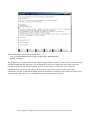
A.1. Check the existing setup
Log into the RPi using PuTTY and enter the following at the prompt. The default user and password is “pi” and
“Callisto_X!” without quotes:
cat /etc/network/interfaces
Note the line that indicates the interface named eth0 uses DHCP:
iface eth0 inet dhcp
Enter the following at the prompt:
ifconfig
See last page for copyright and document information, File: Reeve_RPi-LWATV.doc, Page 15
Note the information to the right of eth0:
eth0
Link encap:Ethernet
inet addr:10.0.0.11
HWaddr b8:27:eb:13:40:76
Bcast:10.0.0.255 Mask:255.255.255.0
In the above example:
inet addr: 10.0.0.11 (current IP address, example)
Bcast:
10.0.0.255 (broadcast IP range, example)
Mask:
255.255.255.0 (subnet mask, example)
Your console screen most likely will show different values. Copy the following details from your console:
inet addr:
________________ (your current IP address)
Bcast:
________________ (your broadcast IP range)
Mask:
________________ (your subnet mask)
Now enter the following at the prompt:
netstat -nr
See last page for copyright and document information, File: Reeve_RPi-LWATV.doc, Page 16
Note the information shown in the Destination and Gateway columns:
Destination: 10.0.0.0 (network destination)
Gateway:
10.0.0.1 (gateway address)
Your console screen most likely will show different values. Copy the following details from your console:
Destination: _____________________ (your network destination)
Gateway:
_____________________ (your gateway address)
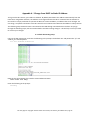
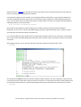
A.2. Edit the network configuration
Use the built-in editor nano to edit the network interface configuration file:
sudo nano /etc/network/interfaces
Using the keyboard cursors, move to the end of the line that reads:
iface eth0 inet dhcp
Replace dhcp with static, as in:
iface eth0 inet static
Directly below the iface line uncomment (delete the # character) the following lines and replace the address
parameters with those you obtained previously. Do not enter the text in parentheses below:
# address 10.0.0.11
(use the inet address)
# netmask 255.255.255.0
(use the subnet mask)
# network 10.0.0.0
(use the network destination)
# broadcast 10.0.0.255
(use the broadcast IP range)
# gateway 10.0.0.1
(use the gateway address)
The address field is the static IP address to be assigned to the RPi. It does not necessarily have to be the address
originally assigned by the LAN router but it must be within the router’s network range.
See last page for copyright and document information, File: Reeve_RPi-LWATV.doc, Page 17
Your console should look similar to above but it will have your parameter values.
Now press CTRL+X (Exit), Y (Yes) and then ENTER to save the changes.
Reboot the RPi so the changes can take effect:
sudo reboot
A.3. Check Static IP Configuration
After the RPi reboots, restart the PuTTY session (right-click the title bar at top of PuTTY window and select
Restart Session), log into the RPi and enter:
ifconfig
See last page for copyright and document information, File: Reeve_RPi-LWATV.doc, Page 18
Double-check your work by pinging the gateway (the -c 5 command line switch indicates to ping 5 times. Note:
Without the –c 5 switch the address will be pinged continuously. To stop continuous ping, press CTRL+C). Also,
be sure to use the IP address of your gateway (router) and not the one shown here:
ping 10.0.0.1 -c 5
The pings should be successful with no packet loss. If not successful, then your setup is incorrect. Recheck each
step above. If necessary, you can revert to DHCP by reversing the steps or by looking at your screenshots before
the changes.
You must reboot after making any interface changes:
sudo reboot
Alternately, instead of reboot, you also can simply stop and restart the RPi network:
sudo /etc/init.d/networking stop
sudo /etc/init.d/networking start
See last page for copyright and document information, File: Reeve_RPi-LWATV.doc, Page 19
Appendix B ~ Install Wireless LAN (WLAN)
Adding a wireless LAN connection to the RPi requires only a USB wireless access device (also called WLAN dongle
and Wi-Fi dongle) and some changes to the network interface configurations. Note: A USB BlueTooth dongle is
physically identical to the Wi-Fi dongle but is not compatible with this application. Most Wi-Fi dongles are
marked 802.11n.
The following steps assume the RPi is initially connected to the LAN through a a wired Ethernet cable. DO NOT
plugin the Wi-Fi dongle until told to do so. As you go through the following steps, take screenshots before and
after making changes – this will help in case you need to reverse your changes.
It should be remembered that a Wi-Fi dongle derives power from the RPi USB port and this power is in addition
to that required by the RPi itself. The dongle should be plugged into the USB port BEFORE power is applied to
the RPi; otherwise, the RPi will reboot because of the momentary voltage drop on its power bus. This is a design
deficiency in the RPi and can result in program corruption.
B.1. WLAN Dongle
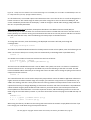
WLAN dongles are inexpensive and easy to obtain; for example, the Edimax EW7811Un Nano, 150Mbps 802.11n Wi-Fi USB Adapter costs 7 USD. These devices have a
very small antenna so their range is limited but ≥ 3 m between the dongle and a
wireless router or wireless access point should be achievable in most situations.
Caution: Some WLAN dongles use power management by default and they will go into sleep mode after a period
of inactivity. Sleep mode is manifested as a “dead” Wi-Fi connection from which the device will not recover
without rebooting the RPi. This is a well-known problem when these devices are used in the RPi, and the
solution depends on the chipset used in the dongle itself. The software image includes a configuration file that
solves this problem for the RealTek 8192cu/RTL8188CUS chipset used in many Wi-Fi dongles. If your Wi-Fi
dongle has that chipset, you should not have any problems. If your WLAN device does not operate reliably then
you will have to revert to a wired network connection.
B.2. Wi-Fi Setup Details
Check the configuration of the Wi-Fi access point to which you plan to connect. You will need to determine:
SSID
Password (or key)
Encryption type and method (for example, WPA and TKIP shared-key encryption)
Procedures for determining these parameters vary widely so you will need to refer to the wireless access point
user guide or do online research. The setup described in the following paragraphs assumes your Wi-Fi network
broadcasts the SSID (Service Set Identifier).
See last page for copyright and document information, File: Reeve_RPi-LWATV.doc, Page 20
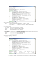
B.3. Setup W-Fi Configuration
Do not yet plug in the Wi-Fi dongle. Log into the RPi and enter the following commands:
sudo nano /etc/network/interfaces
Note the following lines. Do not change them:
auto lo
iface lo inet loopback
iface eth0 inet static
The above form the basic wired network interface configuration in which the RPi uses a static IP address (see
Appendix A). The lines that immediately follow show the static IP configuration. If your RPi is setup to use DHCP,
the third line of text will read as follows and there will be no addressing:
iface eth0 inet dhcp
Also note the following lines, which provide basic WLAN configuration details. Do not change them. The WLAN
configuration is defined by the wpa_supplicant.conf file:
allow-hotplug wlan0
iface wlan0 inet dhcp
wpa-conf /etc/wpa_supplicant/wpa_supplicant.conf
iface default inet dhcp
Press CTRL+X (Exit) to exit the nano editor.
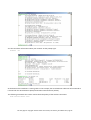
It is necessary to edit the configuration file. At the RPi prompt, enter the following command:
sudo nano /etc/wpa_supplicant/wpa_supplicant.conf
See last page for copyright and document information, File: Reeve_RPi-LWATV.doc, Page 21
Note the following two lines. Do not change them:
ctrl_interface=DIR=/var/run/wpa_supplicant GROUP=netdev
update_config=1
The configuration file supplied with the RPi software image includes a number of additional lines, all commented
out (deactivated) with the # character. Use the keyboard arrow keys to navigate the text and then make the
changes necessary for your wireless network. The first two parameters, ssid and psk, are the SSID and
PASSWORD values, and proto, key_mgmt, pairwise and auth_alg are the Encryption type and method
mentioned in par. B.2. To activate the WLAN, delete the # character and edit the values shown according to your
network details. When finished, the configuration file should look something like this:
See last page for copyright and document information, File: Reeve_RPi-LWATV.doc, Page 22
When done editing the file, press CTRL+X (Exit), Y (Yes) and ENTER to save and exit the configuration file.
If you have more than one Wi-Fi network at your station, you can add the details for each network in the
wpa_supplicant.conf file. The RPi will then connect to the one with the best signal. For a setup with multiple
networks, the text lines “network = { additional network details }” will need to be determined and specified for
each network.
Now, shut down the RPi:
sudo halt
All LED indicators on the RPi board except the red power LED will extinguish when the shutdown is complete.
When the shutdown is complete, remove power.
B.4. Install the WLAN Dongle
With power disconnected from the RPi, unplug the Ethernet cable and plug the WLAN dongle into any USB port
on the RPi. Connect power to RPi. As it boots, the power LED (red) will be steady and the Activity LED should
flash. After a moment, the RPi should automatically connect to your wireless access point. The RPi is setup to
use DHCP and will request an IP address from the router. Most WLAN dongles have a status LED, which should
flash when initialized. The LED will flash at about 1 Hz rate with occasional shorter, irregular flashes indicating
activity. If the status LED does not light at all or continues to flash at only 1 Hz rate for more than a minute (with
no occasional flashes), there may be a problem in your setup.
You will not be able to log into the RPi until you determine the wireless IP address and then setup the SSH client
(PuTTY) to use that address. Check your router or use a network scanning program (for example, SoftPerfect
See last page for copyright and document information, File: Reeve_RPi-LWATV.doc, Page 23
Network Scanner, {NetScan}) to find the hostname (same hostname as the wired network connection but this
time it most likely will have a different IP address).
If the RPi fails to appear on the network, you can plug the Ethernet cable back in, log into the wired Ethernet
interface and double-check the above steps. You most likely made a typing error. After finding and fixing the
error, you can either restart the network interface or reboot the RPi. To restart the network interface (without
rebooting the RPi), at the prompt enter
sudo /etc/init.d/networking restart
Disconnect the wired Ethernet cable and log into the wireless interface using the wireless IP address.
Remember, do not insert or remove the WLAN dongle with power applied to the RPi, but it is okay to remove
and install the wired LAN connection with power on.
It is recommended that either wireless LAN or wired LAN be used but not both at the same time. If wired LAN is
to be used, remove the WLAN dongle (with RPi power off). If wireless LAN is to be used, remove the wired LAN
connection.
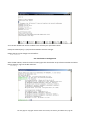
After logging into RPi, you can check the wireless connection quality. At the RPi prompt, enter:
iwconfig
To the right of the wlan0 interface the details include the SSID, frequency, bit-rate, link quality, signal level and
noise level plus other information about the wireless connection. To see packet information and IP addresses for
all connected interfaces enter (in the following example, both the wired and wireless connections are active):
ifconfig
See last page for copyright and document information, File: Reeve_RPi-LWATV.doc, Page 24
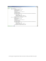
You also can obtain information about your network. At the prompt type:
netstat –nr
At the bottom of the window is a routing table. In this example, the wired Ethernet cable was left connected so
it shows both the wired Ethernet (eth0) and wireless LAN connection (wlan0).
The following commands also can be used to check the quality of the wireless connection:
sudo iwlist wlan0 scan
See last page for copyright and document information, File: Reeve_RPi-LWATV.doc, Page 25
See last page for copyright and document information, File: Reeve_RPi-LWATV.doc, Page 26
Document information
Author:
Whitham D. Reeve
Copyright: © 2014 W. Reeve
Revision: 0.0 (Original draft started, 29 Aug 2014)
0.1 (Numerous additions based on model B, 9 Sep 2014)
0.2 (Draft completed, 16 Sep 2014)
0.3 (Added suspension feature, 17 Sep 2014)
0.4 (Added equipment list, 18 Sep 2014)
0.5 (Added warnings, 22 Sep 2014)
0.6 (2nd Draft completed, 30 Sep 2014)
0.7 (Added Administrator, 4 Oct 2014)
1.0 (Corrected a couple spelling errors and distributed, 27 Nov 2014)
1.1 (Minor clarification beam pointing view, 06 Jan 2015)
1.2 (Added Appx A and B, 05 Feb 2015)
See last page for copyright and document information, File: Reeve_RPi-LWATV.doc, Page 27