1
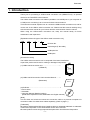
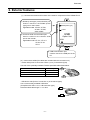
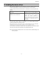
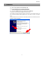
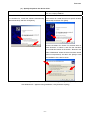
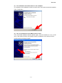
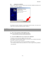
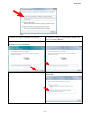
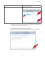
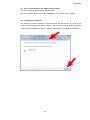
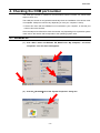
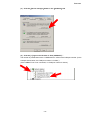
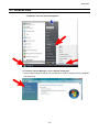
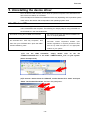
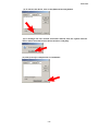
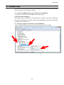
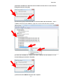
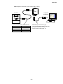
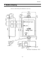
E6581299③ USB-to-Serial Conversion Unit Instruction Manual USB001Z Contents Safety precautions·································································································································1 1. Introduction ······································································································································4 2. Exterior features·······························································································································5 3. Installing the device driver ···············································································································6 3.1. Windows XP····················································································································· 7 3.2. Windows Vista················································································································ 10 4. Checking the COM port number ····································································································14 4.1. Windows XP··················································································································· 14 4.2. Windows Vista················································································································ 16 5. Uninstalling the device driver ·········································································································18 5.1. Windows XP··················································································································· 18 5.2. Windows Vista················································································································ 20 6. 7. 8. 9. Connecting and starting the USB001Z unit····················································································22 Outline drawing ······························································································································24 Specifications·································································································································25 Warranty ········································································································································25 NOTICE 1. Make sure that this instruction manual is delivered to the end user of USB-to-serial conversion unit. 2. Read this manual before installing or operating the USB-to-serial conversion unit. Keep it in a safe place for reference. 3. All information contained in this manual is subject to change without notice. Please confirm the latest information from the member service of web site “www.inverter.co.jp”. E6581299 Safety precautions The items described in these instructions and on the inverter itself are very important so that you can use the inverter safely, prevent injury to yourself and other people around you as well as to prevent damage to property in the area. Thoroughly familiarize yourself with the symbols and indications shown below and then continue to read the manual. Make sure that you observe all warnings given. Explanation of markings Marking Meaning of marking WARNING Indicates that errors in operation may lead to death or serious injury. CAUTION Indicates that errors in operation may lead to injury (*1)to people or that these errors may cause damage to physical property.(*2) (*1) Such things as injury, burns or shock that will not require hospitalization or long periods of outpatient treatment. (*2) Physical property damage refers to wide-ranging damage to assets and materials. Meanings of symbols Marking Meaning of marking Indicates prohibition (Don’t do it). The prohibition detail will be described in or near the symbol in either text or picture form. Indicates something mandatory (must be done). The mandatory detail will be described in or near the symbol in either text or picture form. Indicates caution. The caution detail will be described in or near the symbol in either text or picture form. ■ Limit in purpose Safety precaution ▼ Never use the USB-to-serial conversion unit with any device other than a TOSVERT series inverter, or it will cause an accident. - 1/26 - E6581299 ■ General Operations WARNING Never disassemble, modify or repair. This can result in electric shock, fire and injury. For repairs, call your sales agency. Disassembly prohibited Do not place or insert any kind of object into the unit(electrical wire cuttings, rods, wires). This can result in electric shock or fire. Prohibited Do not allow water or any other fluid to come in contact with the unit. This can result in electric shock or fire. If the unit begins to emit smoke or an unusual odor, or unusual sounds, immediately turn power off. If the equipment is continued to operate in such a state, the result will be fire. Call your local sales agency for repairs. Mandatory ■ Transportation & installation WARNING Don’t place any inflammable objects nearby. If a flame is emitted due to malfunction, it will result in a fire. Prohibited Don’t install in any location where the unit could come into contact with water or other fluids. This can result in electric shock or fire. Mandatory Must be used in the environmental conditions prescribed in the instruction manual. Use under any other conditions will result in malfunction. Provide your inverter or other equipment with safety devices to prevent a serious accident from resulting even if the unit malfunctions or fails to operate. Usage without a safety device can result in an accident. CAUTION Do not connect a LAN cable or modular cable for telephones to the conversion unit. Doing so will cause a failure or accident. Prohibited Do not connect more than one conversion unit to one host device (computer). Doing so will cause a failure or accident. Mandatory Use the Toshiba-specified cable for connecting this optional unit. (Refer to page 5.) The use of any other option will result in an accident. The following steps must be performed before wiring to an inverter. (1) Turn off all input power to the inverter. (2) Wait at least 15 minutes and check to make sure that the charge lamp of inverter is no longer lit. (3) Use a tester that can measure DC voltage 800VDC or more, and check to make sure that the voltage to the DC main circuits (between PA/+ and PC/-) is 45V or less. If these steps are not properly performed, the wiring will cause electric shock. -2- E6581299 ■ Operations WARNING Even if this product is deactivated by the occurrence of an event such as an abnormality, when power is supplied to the inverter, do not bring any regions of your Prohibited body into contact with the inverter terminals. Contact during the power-on status of the inverter can result in electric shock. CAUTION Do not apply a dropping shock or other physical shocks. Otherwise, damage or malfunction will result. Prohibited Do not yank the interconnect cable. Otherwise, damage or malfunction will result. Do not disconnect the USB cable during communication with the inverter. Otherwise, damage or malfunction will result. ■ Cautions in using the unit Notes Do not install the unit where it will be exposed to abrupt changes in temperature or humidity. Leave space between the interconnect cable (between the inverter and the USB device) and the power cable from the inverter. Or the inverter could malfunction because of noise. Do not connect the conversion unit to more than one inverter. Connect the conversion unit to either the “RS485 (2-wire type)” port or the “LOGIC” port on your inverter, depending on the type of the inverter. Avoid connecting the conversion unit to a USB hub or extended USB port (e.g., PCMCIA card). Or else the conversion unit may become unstable, depending on the environment in which it is used. To allow an emergency stop by means of an external device, insert a magnetic contact or similar device between the inverter and the power supply. ■ Cautions in creating a software program Notes The communications software created based on the instruction manual for each TOSVERT series communication function can be used as-is, if the COM port number is changed properly. The conversion unit may, however, be detached from the operating system as a result of a transmission error due to noise, and therefore the occurrence of transmission timeout errors should be monitored using the software, and if they occur in succession, open the port again. -3- E6581299 1. Introduction Thank your for purchasing a “USB-to-serial conversion unit (USB001Z unit),” an optional device for the TOSVERT series inverters. The USB-to-serial conversion unit makes it possible to use a USB port on your computer as a COM port for connecting it to an inverter for data communications. This instruction manual explains how to connect the USB-to-serial conversion unit, and for correct use of the USB-to-serial conversion unit. Please read this manual carefully along with the instruction manual for your inverter and the communication function manual. When using the USB-to-serial conversion unit, keep this manual handy for future maintenance and inspections. [Explanation about the type of the USB-to-serial conversion unit] USB 001 Z 2 Revision No. Cable length (Z: No cable) USB option No. USB option [Accessories check] The USB-to-serial conversion unit is composed of the items listed below. Unpack the product and check for missing or damaged components. (1) USB-to-serial conversion unit ...................................... 1 (USB001Z) RS485 type) (2-wire LOGIC USB Option Unit USB (2) USB-to-serial Conversion Unit Instruction Manual ....... 1 (E6581282) Instruction Manual (3)CD-ROM.......................................................................... 1 - Device driver - Uninstaller - Instruction Manual (Detailed version) (E6581298: Japanese manual, E6581299: this English manual) [Note] This unit does not include an inverter-unit connection cable or a personal computer-unit connection cable. Purchase these cables separately. (Refer to page 5.) [Trademark] Microsoft®, Windows® and Windows Vista® are either a registered trademark or trademark of Microsoft Corporation in the United States and/or other countries. Microsoft product screen shot(s) reprinted with permission from Microsoft Corporation. -4- E6581299 2. Exterior features (1) Here are the names and functions of the exterior components of the USB001Z unit. 1) RS485 (2-wire type) communication port Used to connect to the RS485 (2-wire type) port on the inverter Applicable model: VF-nC3, VF-FS1, VF-AS1, VF-PS1, other models 2) Common serial communication port Used to connect to the common serial port on the inverter Applicable model: VF-S11, VF-nC1 VF-S9, VF-A7 VF-P7 RS485(2wire type) LOGIC USB Option Unit USB 3) USB communication port Used to connect to a USB port on the PC (2) Interconnect cables (No cables are included with this converter unit.) - Inverter side (Point of connection: Either 1) or 2) in the above figure) Use one of the optionally available Toshiba-specified cables listed below. Inverter-to-unit interconnect cable CAB0011 CAB0013 CAB0015 Cable length 1.2m 3.6m 4.8m - USB device side (Point of connection: 3) in the above figure) Use a commercially available USB cable. (Compliant with USB 1.1/2.0, A-B connection type) Recommended cable length: 1 m or less -5- E6581299 3. Installing the device driver When using the USB001Z unit for the first time, you have to install its driver on your computer. These steps do not need to be performed from the next time onward. In order to install, there are two methods shown in a table below. This manual explains both methods. the method of using the CD-ROM of accessories the method of using the downloaded installation file from our company WEB site First insert the CD-ROM delivered with Download “ USB001Z_V208.zip” file from USB001Z into the CD-ROM drive. Toshiba Schneider Inverter Corporation website. (The member registration is required.) Extract the files from the .zip folder and place it in an appropriate location on your system. The device driver (version V208) in the CD-ROM or in our company WEB site doesn't correspond to Windows 98, so please be careful. When the device driver of the previous version is already installed, be sure to install after uninstalling a previous version. Refer to Chapter 5 for the un-installation method. Since the steps to be followed to install the driver vary depending on the operation system used, refer to the section that corresponds to the operating system used. Note: Unless otherwise specified, the term “click” means “left-click” (default setting) in the following chapters. -6- E6581299 3.1. Windows XP * In this example, Windows XP SP3 is used. (1) Turn on your computer and start Windows XP. Note: Log on to Windows XP as a computer administrator. (2) Connect the USB001Z unit to the computer with a USB cable. * At this time, do not connect the USB001Z unit to the inverter. The message “Found New hardware” appears on the screen of your computer monitor, and the “Found New Hardware Wizard” appears after a short while, as shown in the figure below. Click the checkbox for “No, not this time” in the window, make sure a check mark is put in the checkbox, and then click [Next]. -7- E6581299 (3) Specify the path to the device driver. the method of using the CD-ROM of accessories the method of using the downloaded installation file from our company WEB site In the “Found New Hardware Wizard” window, click In the “Found New Hardware Wizard” window, click the checkbox for “Install the software automatically the checkbox for “Install from a list or specific location (Recommended)” and then click [Next]. (Advanced)” and then click [Next]. Click the checkbox for “Search for the best driver in these locations.” to select it, and click the checkbox for “Include this location in the search.” Browse to the folder “GDM20802” where the driver has been stored (when uncompressed). And then click [Next] to start the installation of the device driver. * If the message “USB001Z has not passed Windows Logo testing to verify its compatibility with Windows XP.” appears during installation, click [Continue Anyway]. -8- E6581299 (4) The installation of the device driver is now complete. On completion of the installation of serial converter driver, the window shown below appears. Then, click [Finish]. (5) Then, the installation of the USB port driver starts. The “Found New Hardware Wizard” appears again. Click the checkbox for “No, not this time” in the window, and then click [Next] to start the installation of the serial port driver. Perform steps (2) through (4) again. -9- E6581299 (6) Complete the installation. When a window appears, telling you that the driver has been installed successfully, click [Finish] to complete the installation. The COM port number is needed for communications with the inverter. So, check on the COM number, following the steps described in Chapter 4. 3.2. Windows Vista * In this example, Windows Vista SP2 is used. (1) Turn on your computer and start Windows Vista. Note: Log on to Windows Vista as a computer administrator. (2) Connect the USB001Z unit to the computer with a USB cable. * At this time, do not connect the USB001Z unit to the inverter. The message “Found New hardware” appears on the screen of your computer monitor after a short while, as shown in the figure below. Select “Locate and install driver software (recommended)” in the window. * If the message “Windows needs your permission to continue” appears during installation, click [Continue]. - 10 - E6581299 (3) the method of using the CD-ROM of accessories the method of using the downloaded installation file from our company WEB site Insert the CD-ROM delivered with USB001Z into the Select “I don’t have the disk. Show me other options.” CD/DVD drive. Then click [Next]. - Select “Browse my computer for driver software (advanced)”. - 11 - E6581299 the method of using the CD-ROM of accessories - the method of using the downloaded installation file from our company WEB site Browse to the folder “GDM20802” where the driver has been stored (when uncompressed) and click [Next]. * If the message “Windows can’t verify the publisher of this driver software” appears during installation, click “Install this driver software anyway”. (4) The installation of the device driver is now complete. On completion of the installation, the window shown below appears. Then, click [Close]. - 12 - E6581299 (5) Then, the installation of the USB port driver starts. The “Found New Hardware Wizard” appears again. The driver software is also in the folder “GDM20802”. So, perform steps (3) again. (6) Complete the installation. The COM port number is needed for communications with the inverter. So, check on the COM number (example below shows “COM3”), when a window appears, telling you that the driver has been installed successfully. And then click [Close] to complete the installation. - 13 - E6581299 4. Checking the COM port number The COM port number is needed for communications with the inverter. So, follow these steps to check on it. The COM port number is recognized automatically when the installation of the device driver is completed. COM port numbers vary depending on how your computer is set up. * Perform this check with the USB001Z unit connected to your computer, or else the port number cannot be checked. Since the steps to be followed to check the number vary depending on the operation system used, refer to the section that corresponds to the operating system used. 4.1. Windows XP (1) Click “Start” button on Windows XP, RIGHT-click “My Computer,” and select “Properties” from the menu that appears. (2) Click the [Hardware] tab of the “System Properties” dialog box. - 14 - E6581299 (3) Click the [Device manager] button in the [Hardware] tab. (4) Click the [+] sign on the left side of “Port (COM&LPT).” The number in parentheses next to “USB/Serial Port” refers to the COM port number. (In the example shown below, the COM port number is “COM3.”) (If the USB001Z unit is not connected, no COM port number is shown.) - 15 - E6581299 4.2. Windows Vista (1) Click “Start” button on Windows Vista, RIGHT-click “Computer,” and select “Properties” from the menu that appears. (2) Click the “Device Manager” of the “System” dialog box. * If the message “Windows needs your permission to continue”” appears during installation, click [Continue]. - 16 - E6581299 (3) Click the [+] sign on the left side of “Port (COM&LPT).” The number in parentheses next to “USB/Serial Port” refers to the COM port number. (In the example shown below, the COM port number is “COM3.”) (If the USB001Z unit is not connected, no COM port number is shown.) - 17 - E6581299 5. Uninstalling the device driver Not to be able to install normally and to return the personal computer to the state before the device driver is installed, it’s uninstalled. Since the steps to be followed to uninstall the driver vary depending on the operation system used, refer to the section that corresponds to the operating system used. 5.1. Windows XP The uninstall application is used. The un-installation can start even when the conversion unit is connected to the computer. The following is a step by step for using uninstaller on the CD-ROM or in the downloaded files. the method of using the CD-ROM of accessories the method of using the downloaded installation file from our company WEB site Insert the CD-ROM delivered with USB001Z into Download “USB001Z_V208.zip” file from Toshiba the CD-ROM drive. Click “My Computer”, and Schneider Inverter Corporation website. (The then click your CD-ROM drive. Open the folder member registration is required.) Extract the files named “USB001Z_V208”. from the .zip folder and place it in an appropriate location on your system. (1)To run the CDM Uninstaller, simply double click on the file “CDMUninstallerGUI.exe” in the folder “CDMUninstaller_v1.4” on your system. (when uncompressed) (2)To remove a device driver for USB001Z, confirm Vendor ID is “0403” and input “E040” into Product ID text box. And then click [Add] button. - 18 - E6581299 (3) To remove the device, click on the [Remove Devices] button. (4) A message box will confirm successful removal from the system and the device will be removed from the device window. Click [OK]. (5) Click [Cancel] to complete the un-installation. - 19 - E6581299 5.2. Windows Vista Two drivers can be removed using the Device Manager. Do not reverse following (3) (5) in the order by which the driver software are deleted. (1) Connect the USB001Z unit to the computer with a USB cable. * At this time, do not connect the USB001Z unit to the inverter. (2) Open the Device Manager. Click “Start” button on Windows Vista, RIGHT-click “Computer,” and select “Properties” from the menu that appears. And then click the “Device Manager” of the “System” dialog box. For details, refer to section 4.2. (3) Click the [+] sign on the left side of “Port (COM&LPT).” Select “USB001Z Serial Port, right-click on the mouse and select “Uninstall”. - 20 - E6581299 (4)Click the checkbox for "Delete the driver software for this device" on the uninstall dialog box and then click [OK]. (5) Click the [+] sign on the left side of “Universal Serial Bus Controllers.” Select “USB001Z Serial Converter USB001Z”, right-click on the mouse and select “Uninstall” (6) Click the checkbox for "Delete the driver software for this device" on the uninstall dialog box and then click [OK]. (7) Disconnect the USB001Z unit from the computer. - 21 - E6581299 6. Connecting and starting the USB001Z unit To connect the USB001Z unit to your computer, follow these steps: 1) Turn off the input power to the inverter, and after waiting for at least 15 minutes, make sure that the charge lamp on the inverter is no longer lit. (Your personal computer can remain powered on.) 2) Connect a USB cable to the USB port on the USB001Z unit and to a USB port on your computer. When connecting the USB001Z unit to your computer for the first time, you have to install its driver. Refer to Chapter 3. 3) Connect an inverter-unit connection cable (optional) between the communication connector of the USB001Z and that of the inverter. Refer to the instruction manual of the inverter for connection to the connection port of the inverter, and choose either RS485 (2-wire type) side or LOGIC (common serial) side on the USB001Z. At this time, be careful not to apply force to the connectors. RS 485 (2-wire type) side: Connectable to such an RS485 (2-wire type) interface port as that of the VF-nC3, FS1, AS1, or PS1. LOGIC side: Connectable to such a common serial interface port as that of the VF-nC1, S9, S11, A7, or P7. * Connect the cable only to either RS485 or LOGIC. 4) Turn on the power to the inverter, and set communication parameters. * Before disconnecting the USB communication unit, also perform above step 1) beforehand. * Avoid connecting the conversion unit to a USB hub or extended USB port (e.g., PCMCIA card). Or else the conversion unit may become unstable, depending on the environment in which it is used. CAUTION Do not disconnect the USB cable during communication with the inverter. Otherwise, damage or malfunction will result. Prohibited - 22 - E6581299 Example of connection (In the case of the VF-AS1) RS485 type) (2-wire LOGIC USB Option Unit VF-AS1 USB - Inverter-unit connection cable (Optional) Model number Cable length CAB0011 1.2m CAB0013 3.6m CAB0015 4.8m Computer (USB port) - USB cable (A-B connection type) Use a commercially available USB cable. (Compliant with USB 1.1/2.0) Recommended cable length: 1m - 23 - E6581299 7. Outline drawing Here is an outline drawing of the USB001Z unit. (Unit: mm) - 24 - E6581299 8. Specifications Item Model number Specifications USB001Z Model with either an RS485 (2-wire type) connector or a common serial connector (optional). Applicable model Usable applications: PCM001Z (V013 or successor), PCS001Z (V001 or successor) Windows XP SP3, Windows Vista *1 SP1, SP2 However, the personal computer *2 must have a USB port (series A). Indoor operation at an altitude of 1,000m or less and free from direct sunlight, Use environments potentially corrosive or explosive gases, steam, dust particles, dust/dirt, and machining fluids (grinding liquid, coolant, included) Ambient temperature 0 to +50°C Storage temperature -25 to +65°C Relative humidity 20 to 93% (free from condensation and vapor) Vibration 5.9m/s2 (0.6G) or less (10 to 55Hz) (Compliant with IEC 60068-2-6) Cooling method Self-cooling Applicable OS *1: Windows® is listed above as the abbreviation for a Microsoft® Windows® operating system. Microsoft®, Windows® and Windows Vista® are either a registered trademark or trademark of Microsoft Corporation in the United States and/or other countries. *2: No warranty as to the suitability of this product for any computer and any peripheral equipment is either made or implied. 9. Warranty Any part of the unit that proves defective will be repaired free of charge under the following conditions: 1. This product will be repaired free of charge, if some trouble occurs under normal handling within one year of delivery and is caused obviously by a defect in design or workmanship. 2. The warranty applies only to the delivered unit. 3. For the following kinds of failure or damage, the repair cost shall be borne by the customer even within the warranty period. 1) Failure or damage caused by improper or incorrect use or handling, or unauthorized repair or modification of the inverter 2) Failure or damage caused by the unit falling or an accident during transportation after the purchase 3) Failure or damage caused by fire, salty water or wind, corrosive gas, earthquake, storm or flood, lightning, abnormal voltage supply, or other natural disasters 4) Damage due to the use of the USB-serial communication conversion unit for non-intended purposes. 4. If there are any warranty conditions otherwise provided for, those conditions will govern. - 25E -