1
E6581680
Multi-Loader
Parameter writer Instruction Manual
PWU003Z
Notice
1. Make sure that this instruction manual is delivered to the end user of the inverter.
2.
Read this manual before first using the communications function, and keep it handy as a
3.
All information contained in this manual are subject to change without notice. Please
reference for maintenance and inspections.
confirm the latest information on our web site “www.inverter.co.jp”.
E6581680
Safety precautions
On the inverter and in its instruction manual, important information is contained for preventing injuries to users,
damages to assets, and for proper use of the inverter.
Read the instruction manual attached to the inverter along with this instruction manual to completely
understand the safety precautions, the symbols and indications shown below. Please adhere to the contents of
these manuals at all times.
Explanation of markings
Marking
Meaning of marking
Warning Indicates that errors in operation may lead to death or serious injury.
Indicates that errors in operation may lead to injury (*1) to people or that these
Caution errors may cause damage to physical property. (*2)
(*1) Such things as injury, burns or shock that will not require hospitalization or long periods of
outpatient treatment.
(*2) Physical property damage refers to wide-ranging damage to assets and materials.
Meanings of symbols
Marking
Meaning of marking
Indicates prohibition (Don't do it).
What is prohibited will be described in or near the symbol in either text or picture form.
Indicates an instruction that must be followed.
Detailed instructions are described in illustrations and text in or near the symbol.
-Indicates warning.
What is warned will be described in or near the symbol in either text or picture form.
-Indicates caution.
What the caution should be applied to will be described in or near the symbol in either text
or picture form.
1
E6581680
Limitation of use
Safety precaution
Never use this unit with any inverter other than TOSVERT series inverters. Doing so may cause an accident.
Handling in general
Warning
Never
Disassemble
Prohibited
Mandatory
action
Never disassemble, modify or repair the product.
Disassembling the product may cause electric shocks, fire or injuries.
For repairs, call your sales/repair agency.
Do not put or insert foreign objects such as waste cable, bars, or wires into the product.
It may lead to electric shocks or fire.
Do not splash water over the product, and do not wipe the body with a wet cloth.
It may lead to electric shocks or fire.
Turn off input power before wiring.
Wait at least 15 minutes and check to make sure that the charge lamp (on the inverter unit) is no
longer lit.
Turn off the power immediately in case of any abnormalities such as smoke, smell or abnormal
noise.
Neglect of these conditions may lead to fire.
For repairs, call your sales/repair agency.
Transportation and usage
Warning
Prohibited
Mandatory
action
Do not install or operate the inverter if it is damaged or any part of it is missing.
Operating a defective inverter may lead to electric shocks or fire.
For repairs, call your sales/repair agency.
Do not put any flammable material near the product.
It may catch fire due to the product sparking in the case of a malfunction.
Do not connect a LAN cable or telephone modular cable to Parameter writer.
Doing so may cause a failure or accident.
Electrical construction work must be done by a qualified expert.
Connection of input power by someone who does not have expert knowledge may result in fire
or electric shock.
Operate under the environmental conditions prescribed in the instruction manual.
Operations under any other conditions may result in malfunction.
An emergency stop inverter must be installed that fits with system specifications
(e.g. shut off input power then engage mechanical brake).
Operation cannot be stopped immediately by the inverter alone, thus risking an accident or
injury.
Use the attached cable for connecting this optional unit.
The use of any other option may result in an accident.
Caution
Prohibited
Do not use the product in any place subject to vibrations or it may fall.
This may lead to the product falling and causing injury.
Do not use nickel-cadmium rechargeable battery or manganese battery.
This may lead to liquid spill and fire.
Do not use different type of battery together, or new battery and reuse one together
This may lead to liquid spill and fire.
2
E6581680
Operations
Warning
Do not apply a dropping shock or other physical shocks.
Otherwise, damage or malfunction will result.
Do not pull on the cable and connector
It may cause damage or error.
Do not bring any regions of your body into contact with the inverter terminals when power is
supplied to the inverter. Contact during the power-on status of the inverter can result in electric
shock.
Prohibited
Use an additional safety inverter with your inverter or system to prevent a serious accident due
to the unit malfunctions. Usage without an additional safety inverter may cause an accident.
Make sure to check that the parameter data from this product is not accidently copied to the
wrong inverter.
Usage with wrong parameter may result in an accident.
Mandatory
action
Caution
▼
Mandatory
action
Set up “Communication time-out (f803, f804 and f808)” (see the inverter instruction
manual for details) to stop the inverter when Parameter writer is deactivated by an unusual
event such as tripping, an operating error, power outage, failure, etc. Deactivated Parameter
writer may cause an accident, if the “Communication time-out” is not properly set up.
Please back up the data used with this unit.
The stored data might be lost according to using condition of the SD card.
Please be forewarned that our company cannot make compensation for the damage depend on
the loss of the stored data.
Disposal
Caution
Mandatory
action
If you dispose off this unit, have it done by a specialist in industrial waste disposal*. Improper
disposal may result in explosion of capacitors or produce noxious gases, resulting in injury.
(*) Persons who specialize in the processing of waste and known as “Industrial Waste Product
Collectors and Transporters” or “Industrial Waste Disposal Persons.” If the collection, transport
and disposal of industrial waste is done by someone who is not licensed for that job, it is a
punishable violation of the law (Laws in regard to cleaning and processing of waste materials).
Notes on operation
Notes
Avoid using in a place where ambient temperature or/and humidity change sharply.
Keep the transmission cable separate from the power cable of the inverter to prevent the
inverter from malfunctioning due to electromagnetic noise.
The integrity of data storage is guaranteed for up to 5 years.
The operating life of the data storage inverter is 10000 operations.
Do not execute more than 10000 writing operations.
Do not turn off power or remove the connection cable between the inverter and Parameter writer
or take off SD card while a copying operation is in progress. If the inverter power is turned off or
the connection cable is removed while parameters are being copied, data cannot be written
correctly.
Do not copy data from Parameter writer to inverter and inverter to Parameter writer while the
inverter is running. Some of the parameters cannot be written when the inverter is in operation.
When a copying operation is executed between two inverters with different capacities, some of
the parameters that vary with the capacity of the inverters will also be copied. Therefore, when
copying the parameters between inverters with different capacities or voltage class, the type
information parameters of the inverter should always be initialized. See the inverter instruction
manual on how to initialize their parameters.
3
E6581680
Contents
SAFETY PRECAUTIONS ................................................................................................................................. 1
1.
SETUP PROCEDURE ............................................................................................................................. 5
2.
INTRODUCTION ..................................................................................................................................... 6
3.
RECEIPT OF THE PARAMETER WRITER ............................................................................................ 7
3.1. Presentation ........................................................................................................................................ 8
3.2. Description .......................................................................................................................................... 9
4.
CONNECTING THE PARAMETER WRITER.........................................................................................11
4.1. Connection to a PC........................................................................................................................... 11
4.2. Connection to an inverter ................................................................................................................ 12
5.
CONFIGURATION TRANSFERS.......................................................................................................... 13
5.1. Loading a configuration from an inverter ...................................................................................... 13
5.2. Transferring the configuration to an inverter ................................................................................ 14
5.3. Transferring the configuration to more than one inverter using Quick Store ........................... 15
6.
PARAMETER WRITER MENUS ........................................................................................................... 16
6.1. Parameter writer main menu ........................................................................................................... 16
6.2. Action: Load configuration from Parameter writer to inverter .................................................... 17
6.3. Action: Load configuration from inverter to Parameter writer .................................................... 18
6.4. Quick Store mode ............................................................................................................................. 19
6.5. Supervision ....................................................................................................................................... 20
6.6. Parameter settings: Batteries.......................................................................................................... 21
6.7. Parameter settings: Diagnostics..................................................................................................... 22
6.8. Parameter settings: Password ........................................................................................................ 23
6.9. Parameter settings: Display ............................................................................................................ 23
7.
SPECIFICATIONS ................................................................................................................................. 24
8.
WARRANTY .......................................................................................................................................... 24
4
E6581680
1. Setup procedure
Thank you for purchasing Parameter writer (PWU003Z) for TOSVERT series inverters.
Before using Parameter writer, carefully read this instruction manual in order to completely and correctly utilize
Parameter writer’s excellent performance.
After reading this instruction manual, please keep it handy for future reference.
1. Receive and inspect the Parameter writer
Check that the reference printed on the label is the same as that on the purchase order. Remove the
Parameter writer from its packaging and check that it has not been damaged in transit.
2. Connect the Parameter writer (see chapter 4)
- To a PC
- To an inverter
3. Copy inverter configurations (see chapter 5)
- Load a configuration onto the Parameter writer
- Transfer a configuration to an inverter
- Transfer a configuration to several inverters (Quick Store)
4. Parameter writer menus (see chapter 6)
5
E6581680
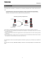
2. Introduction
The Parameter writer “PWU003Z” is a standalone tool for transferring configuration files to inverters with their power on
or off.
•The Parameter writer is used to set inverter parameters by loading a configuration file onto the inverter(s).
(Inverters must have the same reference. If the reference is not the same, the fault occurs before the data is
transfered.). The parameters can be set with them before they are powered up.
Duplicating or generating configuration files
A) The inverter's configuration file is copied to the Parameter writer's SD card. See the procedure on section 5.1.
B) The configuration file is generated by PCM software then transferred to the Parameter writer's SD card. See the
procedure on section 5.1.
1) The user selects and then transfers the configuration file from the Parameter writer to the inverter. See the procedure
on section 5.2.
2) Once the initial transfer is complete, the user can use Quick Store mode, which allows the Parameter writer to load the
same update file on several inverters in succession. (See section 5.3)
All representations of the VF-nC3 inverter throughout this document are given by way of example only to symbolize an
inverter.
All bold text in the manual (e.g. "Main menu / Action") corresponds to the messages displayed on the Parameter writer
screen.
6
E6581680
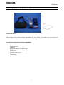
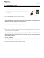
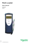
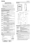
3. Receipt of the Parameter writer
(4)
(5)
(7)
(3)
(6)
(2)
(8)
(1)
Product reference:
Check that the product reference printed on the label is the same as that on the delivery note. This should also
correspond with the number on the purchase order.
Contents of the Parameter writer box (PWU003Z)
Check that the Parameter writer box contains the following:
(1) Parameter writer
(2) SD card
(3) Standard USB type A to Mini-B cable
(4) RJ45 (RJ45/RJ45) cable(Length: 1m)
(5) Carry case
(6) User’s manual (Japanese and English)
(7) Impact resistant cover
(8) Wrist strap
7
E6581680
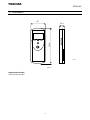
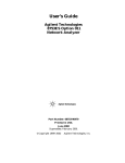
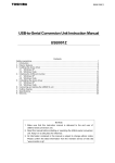
3.1. Presentation
65
27.4
TOSHIBA
ESC
181.5
ENT
( mm )
Figure 1
Approximate weight
250 g (including batteries)
8
E6581680
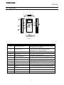
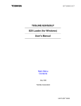
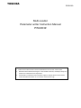
3.2. Description
C
B
H
F
J
TOSHIBA
ENT
I
ESC
D
L
K
A
G
E
M
Figure 2
Letter
Description
Comments
The connection between the Parameter writer (USB
Mini-B type) and the PC (USB type A) is via a 1 m (3.28
feet) USB type A to Mini-B cable.
The connection between the Parameter writer and the
inverter is via a RJ45 cable to load and transfer
configuration files or updated application.
A
Mini-B USB connector
B
RJ 45 connector
C
RJ11 connector with label cover For factory use only.
D
SD card slot
The SD card receives and stores the files. One SD card is
supplied with the Parameter writer.
E
Battery compartment
It can take 4 normal batteries and rechargeable batteries.
F
Power ON/OFF button
Press for 2 seconds to turn the tool on or off.
G
Quick Store key
Press this key to transfer data from the Parameter writer
to the inverter after an initial transfer in Quick store mode.
H
Screen
The screen comprises 2 lines of 16 characters.
I
ESC key
Returns to the previous screen.
J
ENT key
Confirms the parameter selection or cancels messages.
K
Up arrow key
For menu navigation.
L
Down arrow key
For menu navigation.
M
Holes
For wrist strap
9
E6581680
Data storage
One SD card is supplied with the Parameter writer. Any standard SD card and SDHC card are compatible with the
Parameter writer. (SD card is used in this instruction manual for explanation)
The SD card format must be FAT32.
Language
The menus are in English, Japanese, Spanish, German, Italian and French. (Default language is set to English)
Power supplies
Two kinds of batteries are available for powering the Parameter writer:
• 4 x LR6 (AA) alkaline batteries (batteries not attched)
• NiMH rechargeable batteries (batteries and charger not attched)
Battery life
Depending on the type of batteries used, the Parameter writer can transfer up to 300 configuration files.
Power save feature
To prolong battery life, a sleep mode is activated within a programmable time delay; the Parameter writer is reactivated
by pressing the ON/OFF button. (See the display parameters menu on section 6.9.) Connection to a powered-up PC or
inverter can also help conserve battery power, as the power supply from the connected inverter takes over from the
batteries.
Caution
Mandatory
action
Do not use nickel-cadmium rechargeable battery or manganese battery.
This may lead to liquid spill and fire.
It is not possible occasionally to read according to the kind of the SD card and record condition.
It is not warrantable operation and the power supply for all SD cards.
The specification of the SD card might be changed for reasons of manufacturer’s own.
It is not possible occasionally to operate normally according to the changes.
Even if it is the same type-form, the specification might be different in each selling area
according to the SD card.
The data file recorded except the specified format might not to be able to read normally and not
displayed the file name.
The SD card with the security function cannot be used.
The described specification might change without notice.
10
E6581680
4. Connecting the Parameter writer
This section describes the various ways of connecting the Parameter writer.
Default language is set to English. Refer to section 6.9 and change the language setting, according to need.
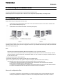
4.1. Connection to a PC
There are two ways of storing files on the SD card:
-Insert the SD card in the Parameter writer and connect the Parameter writer to the PC via the standard USB
type A to Mini-B cable (see Figure 3)
OR
-Insert the SD card in the SD card reader on the PC (see Figure 4)
For both these methods, the SD card is recognized as an external storage device. The SD card operates in Windows
operating system explorer using the same copy/paste actions as any standard external storage media. (OS: Windows
XP/Vista/7 operating system)
Note:
•Windows is the registered trademark of Microsoft Corporation in U.S.A. and other countries.
•The PC must be on and operational before connecting the Parameter writer to avoid an incorrect start up of the PC.
•The SD card must not be removed when the Parameter writer is on and a transfer is in progress. Otherwise, data on
the SD card may be lost.
•The file name length is 255 letters maximum.
•The number of files that can be saved in the SD card is up to 65535 or less.
(N.B. Too many files cause slow key operation response and display. Number of files should be little.)
•The following priority rules come into play when the Parameter writer is connected to a PC:
-If no transfer is in progress between the Parameter writer and the drive, the connection to the inverter is
ignored and the Parameter writer is detected by the PC.
-If a transfer is in progress between the Parameter writer and the inverter, the user has to wait until the transfer
is complete. The Parameter writer must then be reconnected so the PC can detect it.
Source of configuration files
-If a inverter's configuration is to be duplicated, it is copied to another inverter via the Parameter writer. See
"Loading a configuration from inverter" on section 5.1 and "Configuration transfers" on section 5.2 and 5.3.
11
E6581680
4.2. Connection to an inverter
Parameter files can be transferred to the inverter in whichever A and B condition.
A. When the inverter is off, the Parameter writer is powered
B. When the inverter is on, the Parameter writer is powered by the inverter via
the RJ45 cable.
Connect the Parameter writer to the inverter as following procedures
A.
1. Insert the Parameter writer's communication cable into the inverter's RJ45 communication port. Refer to the inverter's
installation manual for more information about how to perform this task.
2. Perform the desired transfer.
3. Remove the Parameter writer communication cable from the inverter.
B.
1. Remove all power from the inverter and all enclosures housing the inverter and wait more than 15 minutes and more
to allow the DC bus of the inverter to discharge.
2. Insert the Parameter writer's communication cable into the inverter's RJ45 communication port. Refer to the inverter's
installation manual for more information about how to perform this task.
3. Install and close all covers and doors before applying power to the inverter. The inverter must be powered on before
performing an upload or download.
4. Perform the desired transfer.
5. Upon completing the transfer, remove all power from the inverter and the enclosures housing the inverter and wait 15
minutes to allow the DC bus of the inverter to discharge.
6. Remove the Parameter writer communication cable from the inverter.
12
E6581680
5. Configuration transfers
5.1. Loading a configuration from an inverter
This procedure allows the user to retrieve a configuration file ("LOADFRMD00.CFG" to "LOADFRMD99.CFG") from an
inverter and load it onto the Parameter writer's SD card.
Main menu
Action
1
ENT
Action Config
MLD -> Device
Action Config
Device -> MLD
ENT
Action Config
XXXXXXXX
Device -> MLD
LoadFrmDxx.cfg
ENT
ENT
LoadFrmDxx.cfg
<<<<
LoadFrmDxx.cfg
<<<<<<<<
LoadFrmDxx.cfg
<<<<<<<<<<<<
Load config
Successful
STEP
1
2
2
Actions
• Turn the Parameter writer on using the ON/OFF button "F" (see section 3.2).
• Connect the Parameter writer to the inverter using the RJ45 cable (see section 4.2).
• Press "ENT" when the screen displays "Main menu / Action".
• Select the "Action Config / Device -> MLD" menu using the arrow keys and press "ENT".
• "Device -> MLD / LoadFromDevicexx" appears on the screen. Press ENT until the transfer
starts.
• "Load Config / Successful" : The configuration has been loaded successfully onto the
Parameter writer;
disconnect the RJ45 cable from the inverter. The inverter configuration file ("filexx.CFG") is
now loaded onto the Parameter writer's SD card.
• Pressing "ENT" returns the user to the "Action Config" menu.
Note :
•If a configuration file has already been loaded 100 files onto the Parameter writer's SD card, it will be overwritten by
the new configuration file from 101 files. Renaming the file on the SD card (via a PC connection) means that the user
can store more than one file on the SD card. ( "file.CFG" can be renamed as "file1.CFG" )
13
E6581680
5.2. Transferring the configuration to an inverter
This procedure allows the user to select the configuration file to be transferred to the inverter.
The user must already have:
-Loaded the inverter configuration file ("*.CFG”) onto the Parameter writer (see section 5.1)
OR
-Generated the configuration file using PCM software and loaded this file onto the Parameter writer
1
Main menu
Action
ENT
Action Config
MLD -> Device
ENT
Action Config
XXXXXXXX
2
MLD -> Device
Filename1
MLD -> Device
Filename2
ENT
MLD -> Device
FilenameN
ENT
ENT
FilenameX
>>>>
FilenameX
>>>>>>>>
FilenameX
>>>>>>>>>>>>
Store config
Successful
3
ENT
STEP
1
2
3
Procedure
• Turn the Parameter writer on using the ON/OFF button “F” (see section 3.2).
• Connect the Parameter writer to the inverter using the RJ45 cable (see section 4.2).
• Press “ENT” when the screen displays “Main menu / Action”.
• Press “ENT” when the screen displays “Action Config / MLD -> Device”.
• Select the file to be transferred using the arrow keys and press “ENT” to start the transfer.
(see section 6.7).
• The configuration has been transferred successfully from the Parameter writer. Disconnect
the RJ45 cable from the inverter.
• Pressing “ENT” returns the user to the “Action Config / MLD -> Device” menu.
Note :
• Keep on pushing ESC key if the process of searching communication mode is canceled.
• Display is changed faster by keeping on pushing
or
key.
14
E6581680
5.3. Transferring the configuration to more than one inverter using Quick Store
This procedure describes how to use the Quick Store function (see section 6.4) to duplicate configurations.
The user must already have:
-Loaded the inverter configuration file (*.CFG) onto the Parameter writer (see section 5.1)
OR
-Generated the configuration file using PCM software and loaded this file onto the Parameter writer
(filename1, filename 2, etc.)
STEP
1
2
3
Transfer
• Turn the Parameter writer on using the ON/OFF button "F" (see section 3.2).
• Connect the Parameter writer to the inverter using the RJ45 cable (see section 4.2).
• Press "ENT" when the screen displays "Main menu / Action".
• Press "ENT" when the screen displays "Action Config / MLD -> Device".
• Select the file to be transferred using the arrow keys and press "ENT" to start the transfer. If
no inverter is connected, a message "No device / connected" appears on the screen
(see section 6.7).
• The configuration has been transferred successfully from the Parameter writer; disconnect the
RJ45 cable from the inverter.
• Connect the Parameter writer to the next inverter, then press the Quick Store key
• "Store Config Successful" : The configuration has been loaded successfully onto the
second inverter; remove the RJ45 cable from the inverter.
• This action can be carried out as many times as necessary.
Note :
• Keep on pushing ESC key if the process of searching communication mode is canceled.
• Display is changed faster by keeping on pushing
or
key.
15
E6581680
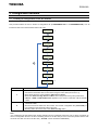
6. Parameter writer menus
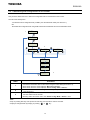
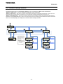
6.1. Parameter writer main menu
On power-up, the "Parameter writer / Version "x.x"" menu is displayed on the screen.
The diagram below shows the various menus that can be accessed from the Parameter writer main menu.
Main menu / Action accesses the following functions:
-Load from Parameter writer to inverter
-Load from inverter to Parameter writer
Main menu / Device accesses the following information:
-Device type
-Device version
Main menu / Parameters accesses:
-Battery parameters
-Diagnostic parameters
-Password parameters
-Display parameters
Main menu / About MLD accesses:
-Parameter writer version information
The Quick Store key (see section 3.2) allows the user to transfer the most recent configuration file or update the inverter
(see section 6.4).
16
E6581680
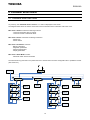
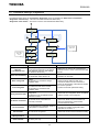
6.2. Action: Load configuration from Parameter writer to inverter
The diagram below shows the "Action Config / MLD -> Device" menu accessible from "Main menu / Action".
"Action Config / MLD -> Device" : This menu accesses the transfer function for loading configurations from the
Parameter writer to the inverter.
Note :
• Keep on pushing ESC key if the process of searching communication mode is canceled.
• Display is changed faster by keeping on pushing
or
key.
17
E6581680
6.3. Action: Load configuration from inverter to Parameter writer
The diagram below shows the "Action Config / Device -> MLD" menu accessible from "Main menu / Action".
"Action Config / Device -> MLD" : This menu accesses the transfer function for loading configurations from the inverter
to the Parameter writer.
Note :
• Keep on pushing ESC key if the process of searching communication mode is canceled.
• Display is changed faster by keeping on pushing
or
key.
18
E6581680
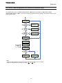
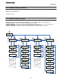
6.4. Quick Store mode
This mode is used to transfer the latest configuration file (See section 5.2). (1)
The diagram below shows the Quick Store mode, which can be accessed after using either of the "Action Config / MLD
-> Device" menus.
Note 1: Quick Store mode can only be used after an initial transfer to an inverter has been completed.
* Files can only be transferred between inverters with the same reference.
19
E6581680
6.5. Supervision
The diagram below shows the device main menu, accessible from "Main menu / Device". This supervisory menu is
used to check the reference and version of the inverter connected to the Parameter writer.
"Device Type" : This menu accesses the reference of the connected inverter.
"Device SW version" : This menu accesses the software version of the connected inverter.
20
E6581680
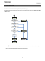
6.6. Parameter settings: Batteries
The diagram below shows the "Parameters / Battery" menu accessible from "Main menu / Parameters".
"Battery / Charge level" : This menu displays the Parameter writer charge level.
"Battery / Alarm level" : This menu is used to set message activation at a particular charge level. It warns the user
about the battery charge status according to the set value (see message fault detected on section 6.7).
"Battery / Set battery type" : This menu is used to select the type of battery used by the Parameter writer (normal
batteries or rechargeable batteries). Users must ensure that the correct battery type is selected so that the Parameter
writer can accurately display the charge level. This also affects message activation.
Parameters
Battery
ENT
ESC
ESC
Battery
Charge level
ESC
Battery
Alarm level
ENT
Battery
Set battery type
ENT
ENT
ENT
Charge level
78%
Press and hold the up
or down arrow key to
define this level value
more quickly.
Alarm level
20%
Value between
[0 and 50] %
Alarm level
NN%
ESC
ESC
Set battery type
Normal
ESC
ESC
Set battery type
Rechargeable
ENT
ENT
Save the level
Save the battery type
21
E6581680
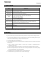
6.7. Parameter settings: Diagnostics
The diagram below shows the "Parameters / Diagnostic" menu accessible from "Main menu / Parameters".
"Diagnostic / Fault History" : This menu accesses the detected fault history.
"Diagnostic / Clear Faults" : This menu is used to clear the detected fault history
Parameters
Diagnostic
ENT
ESC
Diagnostic
Fault History
ESC
Diagnostic
Clear faults
ENT
ENT
ESC
Diagnostic
fault1
ESC
Are you sure to
clear faults?
List of cleared
faults codes
ENT
See the table of
faults codes
below
ESC
Diagnostic
fault2
Clear faults
History done
ENT
ESC
Diagnostic
fault3
Parameter writer display
Warning:
Low Battery Level
Switch off Low battery
Store config fault
Load config fault
Wrong reference Fault
No device connected
No file selected
Probable cause
Remedy
The battery charge is low. The appearance
- Make sure you have a set of replacement
of this message depends on the charge
batteries to hand, as the current set have little
level defined by the user. (See setting
life left.
the detection section 6.6)
The battery charge is too low.
- Replace the batteries immediately. No more
transfers can be made.
The Parameter writer will turn off.
Incomplete or incorrect transfer to the
inverter.
The inverter is in parameter change
prohibition state.
Incomplete or incorrect transfer from
the Parameter writer to the inverter
The inverter is in parameter read
prohibition state.
Bad transfer to the inverter; the
configuration
file selected is not compatible with the
destination inverter.
The inverter is not connected or is
incorrectly connected.
No configuration file is selected. There is
no file present on the SD card.
- Check the RJ45 cable and both of its
connectors. Make sure the connection is
secure for the duration of the transfer. Restart
the transfer operation.
- Confirm the inverter parameter setting.
- Check that the configuration file is compatible
with the inverter to be configured.
- Check the RJ45 cable and both of its
connectors. Make sure the connection is
secure for the duration of the transfer.
Connect the RJ45 cable.
- Select a file to transfer. - Follow the
procedure for loading configuration files
described on section 5.1.
The card is not recognized.
- Check that the SD card is inserted correctly.
- Check that the SD card is formatted correctly.
SD card
Write protected
The SD card is locked.
- Check if the SD card is locked.
Flash FW Fault
For factory use only
-
SD card fault
22
E6581680
6.8. Parameter settings: Password
"Parameters / Password FW"
For factory use only.
6.9. Parameter settings: Display
The diagram below shows the "Parameters / Display" menu accessible from "Main menu / Parameters".
"Display / Contrast" : This menu is used to set the display screen contrast.
"Display / Backlight" : This menu is used to set the display screen time. (OFF, ON, 1 to 5 seconds are selected)
"Display / Sleep mode" : This menu is used to set the Parameter writer's sleep mode.
"Display / Language" : This menu accesses the language selection for the Parameter writer interface.
Parameters
Display
ENT
ESC
ESC
Display
Contrast
ESC
Display
Backlight
ENT
ENT
ESC
Set contrast
50
Display
Language
ENT
ENT
ENT
ESC
ESC
Set backlight
3 sec
ESC
Set contrast
NN
ESC
Display
Sleep mode
Set sleep mode
05 mn
ESC
ENT
Language
English
ESC
ESC
Set backlight
2 sec
Set sleep mode
NN mn
ESC
Language
日本語
ENT
ENT
ESC
ESC
Save the contrast
Set backlight
1 sec
Save the sleep mode
Language
Français
ESC
Press and hold the up
or down arrow key to
define the contrast
value more quickly.
ESC
Set backlight
ON
Press and hold the up
or down arrow key to
define the sleep mode
value more quickly.
ESC
Language
Italiano
ESC
Set backlight
OFF
Language
Deutsch
ENT
Value between
[0 and 100]
Value between
[1 and 60] min
ESC
Save the backlight
Language
Español
ENT
Save the language
23
E6581680
7. Specifications
Item
Part number
Applicable model
Applicable OS
Communication
setting
Applicable battery
Service environment
Protective method
Specifications
PWU003Z
VF-nC3 or successor Note)
Windows XP, Windows Vista, or Windows 7
Communication setting automatic detection
Communication baud rate : 4800, 9600, 19200, 38400 bps
Parity : Non / Even / Odd parity
Communication scheme: RS485
4 x LR6 (AA) alkaline batteries or
4 x NiMH rechargeable batteries
Indoor operation at an altitude of 1,000m or less and free from direct sunlight,
potentially corrosive or explosive gases, steam, dust particles, dust/dirt, and
machining fluids including grinding liquid and coolant
IP20
Ambient temperature
-10 to +50°C
Storage temperature
-25 to +65°C
Relative humidity
20 to 93% (free from condensation and vapor)
Note) Update is needed this product’s software for future inverters.
8. Warranty
Any part of the unit that is proved to be defective will be repaired free of charge under the following conditions:
1. This product will be repaired free of charge, if problem/fault occurs under normal handling within one year of
delivery and is caused obviously by a design or manufacturing defect.
2. The warranty applies only to the delivered unit.
3. For the following kinds of failure or damage, the repair cost shall be borne by the customer even within the
warranty period.
i)
Failure or damage caused by improper or incorrect use or handling, or unauthorized repair or
modification of the inverter.
ii) Failure or damage caused by the unit falling or an accident during transportation after the purchase.
iii) Failure or damage caused by fire, salty water or wind, corrosive gas, earthquake, storm or flood, lightning,
abnormal voltage supply, or other natural disasters.
iv) Damage due to the use of Parameter writer for non-intended purposes.
4. If an additional warranty is provided then those conditions will also apply.
24