1
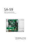
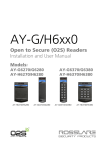
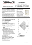
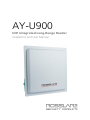
AY-U900 UHF Integrated Long-Range Reader Installation and User Manual Copyright © 2014 by Rosslare. All rights reserved. This manual and the information contained herein are proprietary to ROSSLARE ENTERPRISES LIMITED and/or its related companies and/or subsidiaries’ (hereafter: "ROSSLARE"). Only ROSSLARE and its customers have the right to use the information. No part of this manual may be re-produced or transmitted in any form or by any means, electronic or mechanical, for any purpose, without the express written permission of ROSSLARE. ROSSLARE owns patents and patent applications, trademarks, copyrights, or other intellectual property rights covering the subject matter in this manual. TEXTS, IMAGES, AND ILLUSTRATIONS INCLUDING THEIR ARRANGEMENT IN THIS DOCUMENT ARE SUBJECT TO THE PROTECTION OF COPYRIGHT LAWS AND OTHER LEGAL RIGHTS WORLDWIDE. THEIR USE, REPRODUCTION, AND TRANSMITTAL TO THIRD PARTIES WITHOUT EXPRESS WRITTEN PERMISSION MAY RESULT IN LEGAL PROCEEDINGS. The furnishing of this manual to any party does not give that party or any third party any license to these patents, trademarks, copyrights or other intellectual property rights, except as expressly provided in any written agreement of ROSSLARE. ROSSLARE reserves the right to revise and change this document at any time, without being obliged to announce such revisions or changes beforehand or after the fact. Table of Contents Table of Contents 1. Introduction ....................................................................... 6 1.1 Installation Kit..................................................................................... 6 2. Technical Specifications ................................................... 7 3. Installation ........................................................................ 8 3.1 General .............................................................................................. 8 3.1.1 1-Shaped Stand Bracket Side-Loaded ........................................................... 9 3.1.2 L-Shaped Stand Bracket Top-Loaded ............................................................ 9 3.2 Adjusting the Azimuth Angle of Antenna ............................................ 9 4. Wiring ............................................................................... 11 5. Operation Instructions ................................................... 12 6. Software Installation and Configuration ..................... 13 6.1 Installing the Software ...................................................................... 13 6.2 Connecting the Reader ..................................................................... 16 6.3 Configuring the Reader..................................................................... 17 6.3.1 Tag Type ................................................................................................... 17 6.3.2 Reader RF.................................................................................................. 17 6.3.3 Data Output Setting .................................................................................. 17 6.3.4 Read Mode ............................................................................................... 17 7. UHF Credential Programming ........................................ 18 7.1 Installing the Card Programming Software ........................................ 18 7.2 Programming a UHF Credential ......................................................... 21 A. Limited Warranty ............................................................ 23 AY-U900 Installation and User Manual iii List of Figures List of Figures Figure 1: AY-U900 Reader .............................................................................. 6 Figure 2: Reader Components ........................................................................ 8 Figure 3: Reader Fixing Mode ......................................................................... 9 Figure 4: Antenna Angle Top View ............................................................... 10 Figure 5: Antenna Angle Side View .............................................................. 10 Figure 6: Interfaces ....................................................................................... 11 iv AY-U900 Installation and User Manual Notice and Disclaimer Notice and Disclaimer This manual’s sole purpose is to assist installers and/or users in the safe and efficient installation and usage of the system and/or product, and/or software described herein. BEFORE ATTEMPTING TO INSTALL AND/OR USE THE SYSTEM, THE INSTALLER AND THE USER MUST READ THIS MANUAL AND BECOME FAMILIAR WITH ALL SAFETY REQUIREMENTS AND OPERATING PROCEDURES. The system must not be used for purposes other than those for which it was designed. The use of the software associated with the system and/or product, if applicable, is subject to the terms of the license provided as part of the purchase documents. ROSSLARE exclusive warranty and liability is limited to the warranty and liability statement provided in an appendix at the end of this document. This manual describes the maximum configuration of the system with the maximum number of functions, including future options. Therefore, not all functions described in this manual may be available in the specific system and/or product configuration you purchased. Incorrect operation or installation, or failure of the user to effectively maintain the system, relieves the manufacturer (and seller) from all or any responsibility for consequent noncompliance, damage, or injury. The text, images and graphics contained in the manual are for the purpose of illustration and reference only. All data contained herein subject to change without prior notice. In no event shall manufacturer be liable for any special, direct, indirect, incidental, consequential, exemplary or punitive damages (including, without limitation, any and all damages from business interruption, loss of profits or revenue, cost of capital or loss of use of any property or capital or injury). All graphics in this manual are for reference only, some deviation between the image(s) and the actual product may occur. All wiring diagrams are intended for reference only, the photograph or graphic of the PCB(s) are intended for clearer illustration and understanding of the product and may differ from the actual PCB(s). AY-U900 Installation and User Manual v Introduction 1. Introduction The AY-U900 is a UHF reader that is compatible with multiple protocols and can read multiple tag formats. The reader is waterproof and is suitable for use in a wide range of RFID applications, such as transport management, vehicle management, car parking, production process control, and access control. Figure 1: AY-U900 Reader The AY-U900 series includes the following three models: AY-U900US: 902–928 MHz (America) AY-U900CH: 920–925 MHz (China) AY-U900EU: 865–868 MHz (Europe) 1.1 Installation Kit The AY-U900 package includes: 1 installation and user manual 1 AY-U900 reader 1 switching power supply: 9 VDC, 3 A 1 RS-232 cable 1 DATA communication cable 1 installation bracket kit 6 AY-U900 Installation and User Manual Technical Specifications 2. Technical Specifications Electrical Characteristics Operating Voltage Range 9 to 12 VDC (2 A) Input Current Read: 1.2 A max Credential Read Distance* 1.2 to 12 m (3.9 to 39.4 ft) (adjustable) Transmission Protocol Wiegand 26-Bit (Custom: Wiegand 34-Bit) Maximum Cable Distance 150 m (500 ft) Frequency AY-U900US: 902–928 MHz (America) AY-U900CH: 920–925 MHz (China) AY-U900EU: 865–868 MHz (Europe) Modulation Type ASK Standby: 0.2 A max Read Sensitivity Dual polarization read mode Cards and Tags Rosslare’s AT-T910 and AT-T911 cards ISO18000-6B Tags EPC GEN2 (ISO18000-6C) Tags Environmental Characteristics Operating Temp. Range -20°C to 80°C (-4°F to 176°F) Operating Humidity Range 0 to 95% (non-condensing) Suitable for outdoor use (IP 54) Dimensions Height x Width x Depth 44.5 x 44.5 x 6.7 cm (17.5 x 17.5 x 2.6 in.) Weight 2.32 kg (5.1 lb) * Read range was tested with Rosslare’s AT-T910 card. AY-U900 Installation and User Manual 7 Installation 3. Installation Installation of an RFID reader adjacent to metallic surfaces might alter the reader’s specifications. To diminish this interference, use a plastic spacer when mounting the reader. 3.1 General Figure 2 shows the structure of the reader. Figure 2: Reader Components Installed Fixture Upright Post There are two ways to install the stand-bracket of the AY-U900 reader as shown in Figure 3: 1-shaped stand bracket side-loaded L-shaped stand bracket loaded 8 AY-U900 Installation and User Manual Installation Figure 3: Reader Fixing Mode Reader Reader Road Pavement 1-shaped stand bracket side-loaded L-shaped stand bracket loaded Each installation method is selected based on application requirements and actual location. The user can use the provided template to install AY-U900 reader in more convenient and easier way, but the read distance is a little short; the situation becomes opposite if using the latter. 3.1.1 1-Shaped Stand Bracket Side-Loaded In this method, the stand pole installed to the AY-U900 reader should have a diameter of between 50 and 60 mm and the length of 2.2 m. The pole should be made of stainless steel with a thickness of more than 1.20 mm. Use the fastener contained in package box to mount AY-U900 reader to the top of the stand pole according to actual vehicle type (mainly large car and small car) and then adjust the height from the center of AY-U900 reader to lane level to be around 2.0 m (between 1.8 and 2.2 m). 3.1.2 L-Shaped Stand Bracket Top-Loaded In this method, the L-shaped stand pole (or dragon shape) installed to AYU900 reader should have a diameter of between 60 to 80 mm. The pole should be made of stainless steel with the thickness of more than 1.20 mm. Use the fastener contained in package box to mount AY-U900 reader to the rail near the center of the lane. Adjust the height between the rail and the ground to between 3.5 to 4.0 m, depending on the height of vehicle. 3.2 Adjusting the Azimuth Angle of Antenna The angle of inclination with the ground plane of the antenna should be approximately 60° to 75°, while the deviation angle of the antenna should be biased towards the lane direction (Figure 4). AY-U900 Installation and User Manual 9 Installation Figure 4: Antenna Angle Top View Barrier Gate 30–40° Figure 5: Antenna Angle Side View Reader 60–75° 2.0–2.2 m 10 AY-U900 Installation and User Manual Wiring 4. Wiring The unit has three interfaces (Figure 6): 2-pin power interface RS-232 interface 7-pin interface Figure 6: Interfaces The unit operation voltage is 9–12 VDC, by an independent power supply connected to the 2-pin power interface. The RS-232 serial connection is used to configure the reader through the included software (see Chapter 6). The functions and wiring instructions for the 7-pin interface are shown in Table 1. Table 1: Wiring Function Wire Color Output Wiegand Output Green White Data 0/Data Data 1/Clock Blue Red Black GND Trigger GND Brown Yellow RS-485-A+ RS-485-B- Trigger Mode RS-485 Output AY-U900 Installation and User Manual 11 Operation Instructions 5. Operation Instructions After wiring the unit to a power supply and a controller (Wiegand output, D0, D1, GND), you should test the AY-U900 long-range UHF reader. To test the reader: 1. 2. 12 Power up the reader. One beep is emitted and then it begins an autocalibration procedure. After 2 seconds, the reader enters working mode. Present the appropriate type of credential to the reader. A short beep is emitted, indicating that the credential is read properly. AY-U900 Installation and User Manual Software Installation and Configuration 6. Software Installation and Configuration 6.1 Installing the Software The UHF Reader Setup Application v1.1 is used to configure the reader. To install the UHF Reader Setup Application: 1. 2. Insert the CD into the computer's CD drive. If the Autoloader does not initiate the installation, open My Computer, double-click on the CD drive icon and then double-click the setup file. The installation package extracts the installation files. After the files are extracted, the Welcome to the UHF Reader Application Setup Wizard screen opens. 3. Click Next. AY-U900 Installation and User Manual 13 Software Installation and Configuration The Select Installation Folder screen opens. 4. [Optional]Click Disk Cost…. to ensure the computer has sufficient space. The UHF Reader Application Setup Disk Space window opens. 5. Select the users allowed to use the program, Everyone or Just me. For security purposes it is suggested that Just me is selected. 6. 7. 14 [Optional] You can change the destination folder of the installation: a. Click Browse. b. The standard Windows Explorer window opens. Navigate to and select the required folder. Click Next to continue the installation process. AY-U900 Installation and User Manual Software Installation and Configuration The Confirm Installation screen opens. 8. Click Next. The installation process is initiated. When the process finishes, the Installation Complete screen opens. 9. Click Close to complete the installation process. AY-U900 Installation and User Manual 15 Software Installation and Configuration 6.2 Connecting the Reader Once you’ve installed the UHF Reader Setup Application, you must verify that there is a connection between the reader and the software. To connect the AY-U900: 1. 2. Connect the UHF reader to the PC using a RS-232 cable Click the UHF Reader Setup icon on the desktop or select the program from the Rosslare folder in the Start menu. The application opens. 3. From the Comm Port dropdown, select the correct COM port. 4. Click Query. If the connection is successful, the software displays information on the bottom left of the screen to indicate the connection is successful. The current parameters in the reader are displayed. 16 AY-U900 Installation and User Manual Software Installation and Configuration 6.3 Configuring the Reader There are four main sections in the software interface to be configured: Tag Type, Reader RF, Data Output Setting, and Read Mode. To configure the reader: 1. Configure the four sections as needed according to the field descriptions in the subsections below. 2. Click Set to save the settings. 6.3.1 Tag Type Select one of the two types of credentials: ISO 18000-6B EPC GEN2 (ISO 18000-6C 6.3.2 Reader RF There are two parameters in this section. Frequency: Select one of the three kinds of frequencies for the different regions: America, China, or Europe. Power: Use the Power slider to choose a power between 0 and 30 dBm. 6.3.3 Data Output Setting There are two parameters in this part. Interval: Select the rate that the reader uploads credential information to controller (between 0 to 255 seconds). For example, if you set the interval time to 5 seconds, the reader uploads the credential information to the controller every 5 seconds, even if the reader reads the credential many times during those 5 seconds. Format: Select either Wiegand 26 or Wiegand 34. 6.3.4 Read Mode The software can configure the reader to work in one of two modes: Timing mode: The reader reads a credential continually at a reading rate according to the interval time. Trigger mode: The reader starts to read a credential by connecting a red wire (trigger) and a black wire (ground) at a reading rate according to the interval time. The reader stops after the indicated time as set in the Read time(s) spin box. AY-U900 Installation and User Manual 17 UHF Credential Programming 7. UHF Credential Programming The AY-U900 can be used to program UHF credentials using the UHF Card Programmer application. 7.1 Installing the Card Programming Software To install the UHF Card Programmer softw are: 1. Download the installation setup file from the Rosslare site. 2. Double-click the setup file. The installation package extracts the installation files. After the files are extracted, the Welcome to the UHF Card Programming Setup Wizard screen opens. 3. Click Next. 18 AY-U900 Installation and User Manual UHF Credential Programming The Select Installation Folder screen opens. 4. [Optional]Click Disk Cost…. to ensure the computer has sufficient space. The UHF Card Programmer Setup Disk Space window opens. 5. Select the users allowed to use the program, Everyone or Just me. For security purposes it is suggested that Just me is selected. 6. 7. [Optional] You can change the destination folder of the installation: a. Click Browse. b. The standard Windows Explorer window opens. Navigate to and select the required folder. Click Next to continue the installation process. AY-U900 Installation and User Manual 19 UHF Credential Programming The Confirm Installation screen opens. 8. Click Next. The installation process is initiated. When the process finishes, the Installation Complete screen opens. 9. 20 Click Close to complete the installation process. AY-U900 Installation and User Manual UHF Credential Programming 7.2 Programming a UHF Credential The UHF Card Programmer GUI consists of three areas: Comm port setting EPC GEN2 Display area To program a UHF credential: 1. 2. Connect the UHF reader to the PC using a RS-232 cable. Power on the reader. 3. From the Comm Port dropdown in Comm Port setting, select the correct COM port. 4. Click Connect to connect the programmer via RS-232 cable. 5. If the connection is successful, the software displays “Connect reader success” in the display area. 6. From the Format dropdown In EPC GEN2, choose the card ID format you want, Wiegand 26 or Wiegand 34. For Wiegand 26, the card ID range is 1 to 65535, and the Facility code range is 0 to 255. For Wiegand 34, the ID range is 1 to 4294967295. 7. In the ID spin box, enter the ID you want to assign to the credential. 8. If needed, in the Facility code spin box, enter the Facility code. 9. Present the credential to the reader and click Write. If the credential is written successfully, the software displays “write success!” in the display area and the reader emits a beep. The Card ID in the programmer adds 1 automatically. AY-U900 Installation and User Manual 21 UHF Credential Programming If the credential is written unsuccessfully, the software displays “write fail!” in the display area. The Card ID in the programmer does not add 1 automatically. 10. When finished programming, click Disconnect. To read a UHF Card ID: 1. Present the credential to the reader. 2. Click Read icon. If the credential is read successfully, the software displays “Read success!” followed by the card ID in the display area. If the credential is read unsuccessfully, the software displays “Read fail!” in the display area. 3. 22 When finished reading, click Disconnect. AY-U900 Installation and User Manual Limited Warranty A. Limited Warranty The full ROSSLARE Limited Warranty Statement is available in the Quick Links section on the ROSSLARE website at www.rosslaresecurity.com. Rosslare considers any use of this product as agreement to the Warranty Terms even if you do not review them. AY-U900 Installation and User Manual 23 AY-U900 Rosslare Enterprises Ltd. Kowloon Bay, Hong Kong Tel: +852 2795-5630 Fax: +852 2795-1508 [email protected] United States and Canada Rosslare Security Products, Inc. Southlake, TX, USA Toll Free: +1-866-632-1101 Local: +1-817-305-0006 Fax: +1-817-305-0069 [email protected] Europe Rosslare Israel Ltd. Rosh HaAyin, Israel Tel: +972 3 938-6838 Fax: +972 3 938-6830 [email protected] Latin America Rosslare Latin America Buenos Aires, Argentina Tel: +54-11-4001-3104 [email protected] China Rosslare Electronics (Shenzhen) Ltd. Shenzhen, China Tel: +86 755 8610 6842 Fax: +86 755 8610 6101 [email protected] India Rosslare Electronics India Pvt Ltd. Tel/Fax: +91 20 40147830 Mobile: +91 9975768824 [email protected] 0706-0960473+03 Asia Pacific, Middle East, Africa