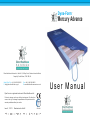
1
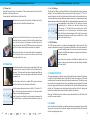
Dyna-Form
®
Mercury Advance
Direct Healthcare Services Ltd Units 8 -10, Withey Court, Western Industrial Estate,
Caerphilly, South Wales, CF83 1BF, UK.
Sales Office Tel: +44 (0) 845 459 9831
E: [email protected]
Fax: +44 (0) 845 459 9832
W: www.directhealthcareservices.co.uk
Dyna-Form is a registered trade mark of Direct Healthcare Ltd.
Products undergo continuous further development. We therefore
reserve the right to change the specifications of the product and the
warranty conditions without prior notice.
Issue 3, 11/1/12
Manufactured in the UK
ISO-9001
User Manual
Dyna-Form ® Mercury Advance User Manual
Dyna-Form
®
Mercury Advance
The Dyna-Form® Mercury Advance Mattress is a “High / Very High
Risk” dynamic replacement system, combined with the benefits
of modern foam technology.
Offering high levels of patient comfort, this unique system has the facility to “step
up” to that of a dynamic mattress when clinically required. Similarly, the mattress‘s
function can be downgraded as the patient’s condition improves. These features
make it particularly beneficial for use within the patient’s home or palliative care
environment and help reduce logistic and decontamination costs. The clinical
benefits of a single system are equally applicable to those of a modern hospital
setting. A higher maximum weight capacity, up to *40 stone / 254kg, allows the
product to meet the modern challenges of those heavier clients. All component
parts are interchangeable and replaceable, maximising product life and reducing
environmental impact.
*Denotes when in Static Mode
CONTENTS
1. INTRODUCTION ......................................2
2. INSTALLATION ........................................2
3. OPERATION .............................................3
4. TRANSPORTATION.................................4
Dyna-Form ® Mercury Advance User Manual
1. INTRODUCTION
The product consists of a “Foam and Air” filled mattress, that rests on top of the bed
platform, and is connected via an umbilical hose, to a separate power/control unit.
In Static Mode, the mattresses attains the pressure reducing properties of the
Dyna-Form® Mercury static foam mattress (details available on request), whilst in
Alternating Mode the mattresses is able to offer similar properties to a pressure relieving
dynamic system. The Mattress consists of a series of 14 transverse
air cells, each containing a unique foam profiled insert, which are
in turn held within a foam U Core, all protected by a vapour
permeable waterproof cover. The transverse cells are arranged
into alternate pairs of A and B cells which are filled and emptied
in sequence while the single head end cell and the formers
remain inflated.
The digitally controlled Power Unit controls a pump that allows air to flow into, or
out of the air cells as required according to the operating mode selected. It also
maintains the air pressure within the mattress at the required level and controls the
action of the audible/visual alarm system in the event of mains supply failure or over
or under inflation pressure. A CPR Valve located at the pump end of the umbilical
hose permits the rapid deflation of the Mattress in an emergency.
2. INSTALLATION
2.1. Mattress
Place the Dyna-Form® Mercury Advance Mattress directly on to the bed platform
ensuring that the Blue multi-stretch waterproof cover is on top and that the umbilical
hose is located at the left hand corner at the foot end of the bed.
Note: The umbilical hose can be located inside the cover under the “Open Here for
Air Inlet” printed in the bottom left hand corner of the mattress. Cover the Mattress
with a loose fitting sheet. In line with MDA/2013/073 the manufacturer warns
against the dangers of smoking in bed
Static Mattress Use
The Dyna-Form® Mercury Advance Mattresses can be used as a pressure reducing
mattress for patients at High / Very High Risk of pressure ulcer damage without the
need to attach the pump.
5. ALARMS...................................................4
6. MAINTENANCE PROCEDURES .............5
7. TECHNICAL DATA...................................6
Alternating Mattress Use
If / When required, the Dyna-Form® Mercury Advance Mattress can be used as an
alternating mattresses system by attaching the Dyna-Form®
Mercury Advance pump system. No other system should be
attached to the mattress as the design settings and internal air
pressure properties of the Dyna-Form® Mercury Advance pump
are specific to this mattress only.
The Dyna-Form® Mercury Advance is a replacement mattress system
and should NOT be placed on top of any existing mattress.
2
Dyna-Form ® Mercury Advance User Manual
Dyna-Form ® Mercury Advance User Manual
2.2. Power Unit
Hang the Power Unit onto the footboard. The mounting hooks swivel to suit the
thickness of the footboard or rail.
Connecting the Umbilical Hose to the Power Unit:
3.1. Lo / Hi Settings
The Dyna-Form® Mercury Advance Mattress, in Alternating Mode, has two pressure
settings. The initial setting that the pump will revert to upon set up is “Lo”. The “Lo”
comfort setting is ideal for the lighter patient of those who feel discomfort when on
a normal alternating air type mattresses system. However, for patients with existing
pressure damage or those at Very High Risk, it is recommended that dependant on the
clinical judgement of the clinician, the “Hi” setting is activated
by pressing the +/- button once, which is located on top
o f t h e pump. In “Hi” Mode the pump attains more of the
characteristics of an alternating air mattresses system
whilst still utilising the advantages of the static foam inserts.
Repeatedly pressing the ‘mode’ button enables the Lo & Hi
modes to be selected in turn.
(a) Open the zip located at the bottom left hand side of the
mattress and pull out the Blue Umbilical hose.
(b) Attach the Blue Umbilical Hose to the power unit by
connecting the air connector at the end of the umbilical hose
to the air inlet connector at the bottom left hand side of the
pump. Ensure that the Red CPR Release button is located on
top of the Air Inlet connector after connection is complete.
(c) Re-close the zip as far as possible without clamping the
Blue Umbilical Hose to ensure the mattress and air cells
are sealed within the cover.
3.2. CPR Deflation
The CPR system consists of a manually operated button located on the Air Inlet
connector attached to the pump. By pressing the Red Button, which will release the
connector locking system, the user can remove the connector
unit which will deflate the mattress air system back to that of a
static foam mattress.
Note: After a short period as the Mattress deflates the ‘Low
Pressure’ alarm is activated and can be cancelled by switching
the Power Unit off.
3. OPERATION
Attach the mains cable to the pump by inserting the “kettle” type
connector into the recess on located on the left hand side of
the pump. The mains cable has been designed specifically as
a removable part to aid in easy replacement should it become
damaged in use.
Plug the mains cable into a suitable 230v mains socket and
switch on the Power Unit using the on/off switch.
After the pump has been turned on both the “Hi “and the “Lo”
lights will flash together intermittently until the pump has
attained its initial operating pressure.
Once the pump has attained its initial operating pressure the
“Lo” light will stay on constantly and the mattress is ready for
use.
4. TRANSPORTATION
To change the location of the bed, remove the Umbilical cord and allow the mattress
to return to its Static Mattress form. Switch off the Power Unit using the on/off switch
and disconnect the electrical supply cable from the mains socket. The bed can now
be moved to a new location where it must immediately be reconnected to the mains
electrical supply and the Power Unit switched back on. Once the Mattress has been
refilled, the ‘Alternating’ mode will automatically revert back to the Lo setting and
should be reselected to Hi should this be desired by the clinician.
Warning: The Mattress will not ‘alternate’ when disconnected from the Power Unit
and /or the mains electrical.
5. ALARMS
Alarm conditions are indicated by a flashing red display accompanied by an audible
warning. In each case the user should respond by turning the Power Unit’s switch
off and investigating the cause.
3
4
Dyna-Form ® Mercury Advance User Manual
Dyna-Form ® Mercury Advance User Manual
5.1. High Pressure Alarm
This condition could be caused, for example by a kinked umbilical hose or visitors,
and others, sitting suddenly on the Mattress.
7. Using suitable brush, hot water, detergent or Hypochlorite solution, clean
Umbilical Hose and CPR Valve. Dry with paper towel.
5.2. Low Pressure Alarm
This condition could be caused, for example, by incorrect fitting of the air inlet connector,
opening of the CPR Valve or a leak in the Mattress due to a cut or puncture.
8. If required, the Mattress Cover may be removed and machine-washed at a
temperature of 90 degrees C, for not less than 10 minutes. The individual Air Cells
can be wiped down with established disinfectants.
5.3. Mains Failure Alarm
If mains power is lost the all Mode lights will turn off. This alarm condition will only
be audible. The red alarm light will not flash.
6.4. Cleaning the Power Unit
The Power Unit can be cleaned by wiping with a cloth dampened with a detergent
solution or Hyperchlorite solution.
6. MAINTENANCE PROCEDURES
7. TECHNICAL DATA
6.1. Safety
Only qualified technicians trained or formally approved by Direct Healthcare Services
Ltd. in the operation and maintenance of Direct Healthcare Services products may
carry out maintenance, modification or repair work on the equipment.
Unqualified personnel attempting to work on Direct Healthcare Services Power Units
risk serious injury to themselves and others and possibly death by electrocution.
7.1. Power Unit
6.2. Cleaning Procedures
Warning: Before cleaning the System make sure that the Power Unit is disconnected
from the mains electricity supply.
Do not immerse the Power Unit in water or other fluids.
Do not autoclave, nor use phenol for cleaning.
Do wash hands before commencing the cleaning process.
Don appropriate protective clothing such as gloves, apron and a mask.
Ensure all work surfaces are cleaned before and after contact with the Mattress.
Protection against shock.............................Class 2
6.3. Cleaning the Mattress
1. With cover left on the Mattress disconnect the Mattress from the Power Unit.
Serial Number.............................................Label on inside of mattress cover
2. Clean the surface of the wash down table with Hypochlorite solution or equivalent
disinfectant.
Dimensions.................................................880 x 1980 x 150 mm (Nominal)
Serial Number.............................................As per label on rear of pump
Electrical Supply.........................................220-240 volt, 50 Hz
Power Consumption...................................10 watts
Fuses..........................................................500 mA
Noise Level................................................. Approx. 30 dB (A)
Dimensions.................................................235 x 180 x 80 mm
Weight........................................................1.7 kg
Service Interval...........................................12 months
7.2 Mattress
Number of Air Cells....................................14 Air Cells / 1 Static Foam Cell
Weight........................................................13.4kg
3. Wash Mattress top using hot water (60 degrees C) containing detergent – dry
with a paper towel.
4. For heavy contamination use a Hypochlorite solution 1,000 parts per million
available chlorine.
5
6