1
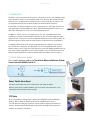
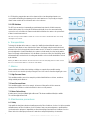
User Manual DIRECTHEALTHCARESERVICES.CO.UK DY N A - F O R M M E R C U RY A D VA N C E The Dyna-Form® Mercury Advance mattress is a “High / Very High Risk” dynamic replacement system, combined with the benefits of modern foam technology. Offering high levels of patient comfort, this unique system has the facility to “step up” to that of a dynamic mattress when clinically required. Similarly, the mattress‘s function can be downgraded as the patient’s condition improves. These features make it particularly beneficial for use within the patient’s home or palliative care environment and help reduce logistic and decontamination costs. The clinical benefits of a single system are equally applicable to those of a modern hospital setting. A higher maximum weight capacity, up to *40 stone / 254kg, allows the product to meet the modern challenges of those heavier clients. All component parts are interchangeable and replaceable, maximising product life and reducing environmental impact. *Denotes when in Static Mode Contents 1. Introduction ...........................................................................................................................3 2. Quick Reference Guide ...........................................................................................................3 3. Troubleshooting.....................................................................................................................4 4. Installation ��������������������������������������������������������������������������������������������������������������������������� 5 5. Operation ����������������������������������������������������������������������������������������������������������������������������� 5 6. Transportation����������������������������������������������������������������������������������������������������������������������� 6 7. Alarms���������������������������������������������������������������������������������������������������������������������������������� 6 8. Maintenance Procedures ������������������������������������������������������������������������������������������������������� 6 9. Technical Data����������������������������������������������������������������������������������������������������������������������� 7 10. Environment conditions for transport, storage and use������������������������������������������������������������� 7 11. Symbols Guide......................................................................................................................7 2 DIRECTHEALTHCARESERVICES.CO.UK USER MANUAL 1. Introduction The Mattress consists of a foam head cell and series of 14 transverse air cells, each containing a unique foam profiled insert, which are in turn held within a foam U Core, all protected by a vapour permeable waterproof cover. The single head end cell and the formers consist of foam only. The transverse cells are arranged into alternate pairs of A and B cells which are filled and emptied in sequence. In Static Mode, the mattress attains the pressure reducing properties of the Dyna-Form Mercury static foam mattress (details available on request), whilst in Alternating Mode the mattresses is able to offer similar properties to a pressure relieving dynamic system. The Mattress consists of a series of 14 transverse air cells, each containing a unique foam profiled insert, which are in turn held within a foam U Core, all protected by a vapour permeable waterproof cover. The transverse cells are arranged into alternate pairs of A and B cells which are filled and emptied in sequence while the single head end cell and the formers remain inflated. The digitally controlled Power Unit controls a pump that allows air to flow into, or out of the air cells as required according to the operating mode selected. It also maintains the air pressure within the mattress at the required level and controls the action of the audible/visual alarm system in the event of mains supply failure or over or under inflation pressure. A CPR Valve located at the pump end of the umbilical hose permits the rapid deflation of the Mattress in an emergency. 2. Quick Reference Guide This is a quick reference guide for the Dyna-Form Mercury Advance System Product Code MAT/MERADV/198/88/15 Power Switch Alarm Reset The power switch simply switches the mains power to the pump on and off. When the pump detects an alarm condition, this can be silenced as below and re-set by switching the pump off and then back on again. CPR Valve Please ensure that the CPR connector is always placed fully home, prior to inflating the mattress. NB: The mattress will NOT inflate properly should this not be the case. The CPR connector is only to be used in the event of a clinical emergency for priority use. However, disconnecting this function will cleverly deflate air rapidly from the mattress in readiness for transport / static mode. DIRECTHEALTHCARESERVICES.CO.UK 3 DY N A - F O R M M E R C U RY A D VA N C E LED Mode Settings This symbol when illuminated indicates that the mattress is powered ON. Simply de-select to power OFF. When a patient requires a true dynamic function or indeed more pressure in the cells, as they may be uncomfortable or feel as though the support surface if too soft or unstable, then please select a “Hi” setting. This must only be used by a trained clinician as often too higher pressures can further agitate certain patients conditions. When a patient requires less pressure in the cells, as they may be uncomfortable or indeed hyper sensitive to cell movement or indeed if the patient is still reddening further, then please select a “Lo” setting. This must only be used by a trained clinician. This function is used to silence the alarm. The LED will remain lit if the alarm has been silenced previously, however a fault is still detected. Refer to the power switch (as above) in order to re-set fully. If the alarm continues to sound repeatedly, along with an illuminated light, then an engineer must be called. Power On / Off True Dynamic /Firmer Setting Lo I Comfort Pressure Setting Silence Alarm This symbol indicates an “Alarm Failure”. Please see trouble shooting guide below for how to re-set. Note: Please ensure that all securing straps on the base of the mattress are secured onto the NON MOVING PARTS of the bed frame. Alarm Failure 3. Troubleshooting Symptoms Problems / Cause Low Pressure The mattress is set to a mode that is too SOFT. Change the mode button to standard (from Lo to High(+) a firmer pressure setting) as required. If the mattress is still too soft after a short period of 5 to 10 minutes, then please call an engineer. The CPR connector is not fully home. Check all tubing is not kinked within the mattress. There may be a leak in the system. High Pressure Points to check Ensure that the tubing within the mattress is fully connected. The mattress is excessively firm on a Set mattress to a softer setting as clinically required. constant basis. Evaluate that the mattress to be of a “less firm” state after a short period of 5 to 10 minutes. If this is not achieved, then please follow the task as below before calling an engineer for assistance. Note: Check all tubing is not kinked within the mattress. 4 DIRECTHEALTHCARESERVICES.CO.UK USER MANUAL 4. Installation 4.1. Mattress Place the Dyna-Form® Mercury Advance Mattress directly on to the bed platform ensuring that the Blue multi-stretch waterproof cover is on top and that the umbilical hose is located at the left hand corner at the foot end of the bed. Note: The umbilical hose can be located inside the cover under the “Open Here for Air Inlet” printed in the bottom left hand corner of the mattress. Cover the Mattress with a loose fitting sheet. Static Mattress Use The Dyna-Form® Mercury Advance Mattresses can be used as a pressure reducing mattress for patients at High / Very High Risk of pressure ulcer damage without the need to attach the pump. Alternating Mattress Use If / When required, the Dyna-Form® Mercury Advance Mattress can be used as an alternating mattresses system by attaching the Dyna-Form® Mercury Advance pump system. No other system should be attached to the mattress as the design settings and internal air pressure properties of the Dyna-Form® Mercury Advance pump are specific to this mattress only. The Dyna-Form® Mercury Advance is a replacement mattress system and should NOT be placed on top of any existing mattress. 4.2. Power Unit (Pump) Hang the Power Unit (Pump) onto the footboard. The mounting hooks swivel to suit the thickness of the footboard or rail. Connecting the Umbilical Hose to the Power Unit (Pump): (a) Open the zip located at the bottom left hand side of the mattress and pull out the Blue Umbilical hose. (b) Attach the Blue Umbilical Hose to the Power Unit (Pump) by connecting the air connector at the end of the Umbilical Hose to the air inlet connector at the bottom left hand side of the pump. Ensure that the Red CPR Release button is located on top of the Air Inlet connector after connection is complete. (c) Re-close the zip as far as possible without clamping the Blue Umbilical Hose to ensure the mattress and air cells are sealed within the cover. 5. Operation Attach the mains cable to the pump by inserting the “kettle” type connector into the recess on located on the left hand side of the pump. The mains cable has been designed specifically as a removable part to aid in easy replacement should it become damaged in use. Plug the mains cable into a suitable 230v mains socket and switch on the Power Unit using the on/off switch. After the pump has been turned on both the “Hi “and the “Lo” lights will flash together intermittently until the pump has attained its initial operating pressure. Once the pump has attained its initial operating pressure the “Lo” light will stay on constantly and the mattress is ready for use. 5.1. Lo / Hi Settings The Dyna-Form® Mercury Advance Mattress, in Alternating Mode, has two pressure settings. The initial setting that the pump will revert to upon set up is “Lo”. The “Lo” comfort setting is ideal for the lighter patient of those who feel discomfort when on a normal alternating air type mattresses system. However, for patients with existing pressure damage or those at Very High Risk, it is recommended that dependant on the clinical judgement of the clinician, the “Hi” setting is activated by pressing the +/- button once, which is located on top of the pump. DIRECTHEALTHCARESERVICES.CO.UK 5 DY N A - F O R M M E R C U RY A D VA N C E In “Hi” Mode the pump attains more of the characteristics of an alternating air mattresses system whilst still utilising the advantages of the static foam inserts. Repeatedly pressing the ‘mode’ button enables the Lo & Hi modes to be selected in turn. 5.2. CPR Deflation The CPR system consists of a manually operated button located on the Air Inlet connector attached to the pump. By pressing the Red Button, which will release the connector locking system, the user can remove the connector unit which will deflate the mattress air system back to that of a static foam mattress. Note: After a short period as the Mattress deflates the ‘Low Pressure’ alarm is activated and can be cancelled by switching the Power Unit off. 6. Transportation To change the location of the mattress, remove the Umbilical cord and allow the mattress to return to its Static Mattress form. Switch off the Power Unit (Pump) using the on/off switch and disconnect the electrical supply cable from the mains socket. The mattress can now be moved to a new location where it must immediately be reconnected to the mains electrical supply and the Power Unit (Pump) switched back on. Once the Mattress has been refilled, the ‘Alternating’ mode will automatically revert back to the Lo setting and should be reselected to Hi should this be desired by the clinician. Warning: The Mattress will not ‘alternate’ when disconnected from the Power Unit (Pump) and /or the mains electrical. Also refer to environmental conditions section at rear of this manual. 7. Alarms Alarm conditions are indicated by a flashing red display accompanied by an audible warning. In each case the user should respond by turning the Power Unit’s switch off and investigating the cause. 7.1. High Pressure Alarm This condition could be caused, for example by a kinked Umbilical Hose or visitors, and others, sitting suddenly on the Mattress. 7.2. Low Pressure Alarm This condition could be caused, for example, by incorrect fitting of the air inlet connector, opening of the CPR Valve or a leak in the Mattress due to a cut or puncture. 7.3. Mains Failure Alarm If mains power is lost the all Mode lights will turn off. This alarm condition will only be audible. The red alarm light will not flash. 8. Maintenance procedures 8.1. Safety Only qualified technicians trained or formally approved by Direct Healthcare Services Ltd. in the operation and maintenance of Direct Healthcare Services products may carry out maintenance, modification or repair work on the equipment. Unqualified personnel attempting to work on Direct Healthcare Services Power Units risk serious injury to themselves and others and possibly death by electrocution. 6 DIRECTHEALTHCARESERVICES.CO.UK USER MANUAL 8.2. Cleaning Procedures Warning: Before cleaning the System make sure that the Power Unit (Pump) is disconnected from the mains electricity supply. Do not immerse the Power Unit (Pump) in water or other fluids. Do not autoclave, nor use phenol for cleaning. Do wash hands before commencing the cleaning process. Wear appropriate protective clothing such as gloves, apron and a mask. Ensure all work surfaces are cleaned before and after contact with the Mattress. 3. Wash Mattress top using hot water (60 degrees C) containing detergent – dry with a paper towel. 4. F or heavy contamination use a Hypochlorite solution 1,000 parts per million available chlorine. 5. Using suitable brush, hot water, detergent or Hypochlorite solution, clean Umbilical Hose and CPR Valve. Dry with paper towel. 6. If required, the Mattress Cover may be removed and machine-washed at a temperature of 80 degrees C, for not less than 10 minutes. The individual Air Cells can be wiped down with established disinfectants. 8.3. Cleaning the Mattress 1. With cover left on the Mattress disconnect the Mattress from the Power Unit (Pump). 2. Clean the surface of the wash down table with Hypochlorite solution or equivalent disinfectant. 8.4. Cleaning the Power Unit (Pump) The Power Unit can be cleaned by wiping with a cloth dampened with a detergent solution or Hypochlorite solution. Also refer to symbol chart. 9. Technical data 11. Symbols Guide 9.1. Power Unit (Pump) Serial Number.............................As per label on rear of pump Electrical Supply.....................................220-240 volt, 50 Hz Power Consumption................................................10 watts Fuses..................................................................... 500 mA Protection against shock............................................Class 2 Noise Level................................................Approx. 30 dB (A) Dimensions............................................235 x 180 x 80 mm Weight...................................................................... 1.7 kg Service Interval....................................................12 months Mattress Symbols 9.2KEEP Mattress DRY REFER TO DO NOT DISPOSE OF USER MANUAL WITH HOUSEHOLD WASTE. Serial Number......................Label onPLEASE insideREFER of mattress cover TO WEBSITE Number of Air Cells................. 14 Air Cells / 1 Static Foam Cell Dimensions......................... 880 x 1980 x 150 mm (Nominal) SUITABLE FOR DOUBLE INSULATED MEDICAL DEVICES Weight.....................................................................13.4kg CONNECTION TO CLASS II APPLIED PART TYPE BF DIRECTIVE 93/42EEC 10. E nvironment conditions for transport, storage and use Mercury Advance Serial No Transport..................................................... -5˚C – +40˚C Storage.........................................................5˚C – +40˚C Usage.........................................................15˚C – +40˚C Humidity........................................................... 10% – 93% WASH AT 80˚ DO NOT TUMBLE DRY DO NOT DRY CLEAN REFER TO USER MANUAL MEDICAL DEVICES DIRECTIVE 93/42EEC SUITABLE FOR CONNECTION TO APPLIED PART TYPE BF DO NOT BLEACH DO NOT IRON NO SMOKING MAXIMUM USER WEIGHT LIMIT 254 KG / 40 STONES DO NOT USE SHARP INSTRUMENTS DO NOT USE PHENOL Pump (Unit) Symbols KEEP DRY REFER TO USER MANUAL DOUBLE INSULATED CLASS II SUITABLE FOR CONNECTION TO APPLIED PART TYPE BF DIRECTHEALTHCARESERVICES.CO.UK DO NOT DISPOSE OF WITH HOUSEHOLD WASTE. PLEASE REFER TO WEBSITE MEDICAL DEVICES DIRECTIVE 93/42EEC 2 7 DY N A - F O R M M E R C U RY A D VA N C E EMI/EMC Statement and Manufacturer’s Declaration This equipment has been tested and found to comply with the limits of EN 60601-1-2 2007. These limits are designed to provide reasonable protection against harmful interference in both a medical and residential environment. This equipment generates, uses and can radiate radio frequency energy and, if not used in accordance with manufacturer’s instructions, may cause harmful interference to radio communications. However, there is no guarantee that interference will not occur in a particular installation. If this equipment does cause harmful interference to radio or television reception or other equipment, which can be determined by turning the equipment off and on, the user is encouraged to try to correct the interference by one of the following measures: • Reorient or relocate the receiving antenna. • Increase the separation between the equipment. • Connect the equipment to an outlet on a circuit different from that to which the receiver or equipment was connected. The equipment having been tested to operate within the limits of electromagnetic compatibility. (Immunity to interference from nearby sources radiating radio frequency energy). Sources exceeding these limits may give rise to operation faults. Where possible the system will sense the interference and if it is of short duration transparently take countermeasures whilst operating near normally, or failing this will issue a warning and take measures for the continued safely of the user. Further increased levels of energy may cause the system to stop operating, continuously generate random faults or continuous resets. Try to ascertain the source of the interference by turning nearby or suspect equipment off, and see if the interference effects stop. In any such event the user is encouraged to try to correct the interference by one of the following measures: • Have the interfering equipment repaired or replaced. • Reorient or relocate the interfering equipment. • Increase the separation between the equipment and the possible source of the interference. • Connect the equipment to an outlet on a circuit different from that to which the interfering equipment was connected. Information regarding Electro Magnetic Compatibility (EMC) according to IEC60601-1-2:2007, clause 6.8 With the increased number of electronic devices such as PC’s and mobile telephones, medical devices in use may be susceptible to electromagnetic interference from other devices. The EMC (Electro Magnetic Compatibility) standard IEC60601-1-2 defines the levels of immunity to these electromagnetic interferences. From the other hand, medical devices must not interfere with other devices. IEC60601-1-2 also defines the maximum levels of emissions for these medical devices. With over 28 years experience in the provision of clinically proven, value for money solutions, you can be sure that our combination of innovative technologies, designed in partnership with leading clinical healthcare establishments, meet the needs of most patient groups, including our increasingly elderly population. Our specialist teams are dedicated to serving your needs by continually striving to provide excellent customer support through a personalised one-on-one service. Whether you need a full hospital installation or a single item, you can be sure that by putting your trust in us – we will ‘Deliver the Promise’. Direct Healthcare Services Ltd Unit 6/10 Withey Court, Western Industrial Estate Lon-y-Llyn, Caerphilly, CF83 1BF UK Sales Office +44 (0) 845 459 9831 F +44 (0) 845 459 9832 E [email protected] www.directhealthcareservices.co.uk Although Direct Healthcare Services Ltd will endeavour to provide the exact specification as printed, we reserve the right to change specification without prior notice. All equipment and information within this brochure, should be used in conjunction with appropriate clinical judgement and nursing procedures. All products manufactured to standards: 8 DIRECTHEALTHCARESERVICES.CO.UK