1
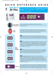
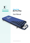
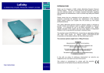
AIR PLUS USER MANUAL
Air Plus User Manual
Alternating pressure mattress for prophylaxis and treatment of pressure sores
Indications for use
• The Air Plus has been developed as a “state of the art” pressure relieving
system for high to very high risk patients.
Contra indications
• As with all alternating mattress systems, the Air Plus is contra indicated for
use where patients have unstable fractures or spinal injuries.
CONTENTS
1. INTRODUCTION ..................................................................................................................... 2 2. INSTALLATION ...................................................................................................................... 2 3. OPERATION............................................................................................................................ 2 4. TRANSPORTATION............................................................................................................... 3 5. ALARMS.................................................................................................................................. 4 6. MAINTENANCE PROCEDURES........................................................................................... 4 7. TECHNICAL DATA................................................................................................................. 5 8. SUPPLIER ADDRESS............................................................................................................ 6 ISSUE 2
PAGE 1 OF 6
AIR PLUS USER MANUAL
1. Introduction
The product consists of an air filled mattress, that rests on top of the bed platform, and is
connected, via an umbilical hose, to a separate power/control unit.
The objective of the product is to relieve the pressure created under a patient, when lying on a bed, so that blood
flow is maintained and tissue oxygenation achieved. It does this by intermittently relieving the pressure from the
patient by sequentially deflating the supporting air cells of the mattress.
The Mattress consists of a series of 17 transverse air cells located within 2 longitudenal side formers, all protected
by a vapour permeable waterproof cover. Sixteen of the transverse cells are arranged into alternate pairs of A and
B cells which are filled and emptied in sequence while the single head end cell and the formers remain inflated.
A foam underside is placed within the Mattress providing secondary support and appropriate height partnership.
The software based system within the Power Unit controls solenoid valves enabling air to flow into, or out of, the air
cells as required according to the operating mode selected. It also maintains the air pressure within the mattress at
the required level and controls the action of the audible/visual alarm system in the event of mains supply failure or
over or under inflation pressure.
A CPR Valve located in the umbilical hose permits the rapid deflation of the Mattress in an emergency.
2. Installation
2.1.
Mattress
Remove the bedding from the conventional mattress.
Place the Air Plus Mattress directly on to the bed platform ensuring that the removable waterproof cover is on top
and that the umbilical hose is at the foot end of the bed. Secure the Mattress to the bed by fastening the two head
end straps to the head platform area of the bed and its mid-position and foot-end straps around the bed platform. The
straps should not be too tight and should not interfere with the operation of the bed. They should be checked
regularly and secured on the moving parts only.
Cover the Mattress with a loose fitting sheet.
2.2.
Power Unit
Hang the Power Unit onto the footboard. The mounting hooks swivel to suit the thickness of the footboard or rail.
Connect the Umbilical Hose to the Power Unit by inserting the 3 male probes into the female quick connect
sockets. The Head Cell/Side Former supply probe is physically non-interchangeable with the other probes. Correct
connection is indicated by an audible ‘click’. Check that the CPR Valve is turned to the ‘Normal’ position.
3. Operation
Plug the mains cable into a suitable 230v mains socket and switch on the Power Unit using the on/off switch. The
LED display is illuminated and will flash 3 green horizontal bars ( _ _ _ ) followed by 3 green zeros ( 0 0 0 ) as the
Mattress is inflated.
Once the Mattress is fully inflated the Power Unit automatically switches into the ‘Dynamic’ mode and the display
changes to alternatively flash ‘_ 0 _’ and ‘0 _ 0’ (in green). The A cells are allowed to deflate for 3 minutes then
during the next 2 minutes they are re-inflated to the working pressure and held there. The process is then repeated
for the B cells so that the whole cycle repeats every 10 minutes.
The ‘Static’ mode in which all the cells remain inflated is selected by pressing the ‘mode’ switch on the control
panel. The LED display changes to ‘ 0 0 0’ and blinks every few seconds as an indication that the system is
operating correctly. If the mode has not already been changed by the user, the ‘Static’ mode is automatically limited
to a maximum time of 2 hours, after which, for reasons of clinical safety, operation reverts to the ‘Dynamic’ mode.
3.1.
Comfort (Version 2 software)
This facility enables the preset mattress inflation pressure to be reduced and so achieve a ‘softer’mattress.
ISSUE 2
PAGE 2 OF 6
AIR PLUS USER MANUAL
The ‘Soft-Dynamic’ mode is selected by selecting the ‘Static’ mode as above and then pressing the ‘mode’ button
again. The display changes to ‘o_o’ and ‘_o_’ and the dynamic cycle operates but at with reduced mattress
pressure.
The’Soft-Static’ mode is selected by pressing the ‘mode’ button again. The display changes to ‘ooo’ and the
mattress remains inflated at the reduced pressure.
Repeatedly pressing the ‘mode’ button enables the ‘Dynamic’, ‘Static’, ‘Soft-Dynamic’ and ‘Soft- Static’ modes to be
selected in turn.
3.2.
CPR Deflation
The CPR Valve consists of a manually operated rotary action valve which, when opened, connects all the Cells and
Formers to atmosphere and so achieving rapid Mattress deflation. For convenience and accessibility the Valve is
mounted in the umbilical hose between the Mattress and the Power Unit.
Turning the red operating knob clockwise to the ‘CPR’ position activates the Valve. As the Mattress deflates the
‘Low Pressure’ alarm is activated and should be cancelled by switching the Power Unit off.
Warning: Close the CPR Valve by rotating the red knob anti-clockwise to the ‘Normal’ position before switching the
Power Unit on again.
4. Transportation
To change the location of the bed, switch the system to ‘Static’ and allow all the Cells to fully inflate. Switch off the
Power Unit using the on/off switch and disconnect the electrical supply cable from the mains socket. The bed can
now be moved to a new location where it must immediately be reconnected to the mains electrical supply and the
Power Unit switched back on. Once the Mattress has been refilled, the ‘Dynamic’ mode will automatically be
selected.
To move just the patient and mattress, e.g. by trolley, switch the system to ‘Static’ and allow all the Cells to fully
inflate. Switch off the Power Unit using the on/off switch and disconnect the umbilical hose by depressing the
actuator buttons on the 3 quick-connect valves on the side of the Power Unit and withdrawing the probes. The
Mattress can now be moved independently and will remain inflated for several hours. It should be reconnected with
the Power Unit and mains electrical supply as soon as possible.
Warning: The Mattress will not ‘alternate’ when disconnected from the Power Unit and /or the mains electrical
supply and hence will not provide optimal pressure relief.
4.1.
Side Formers
The side formers normally remain fully inflated and providing a firm edge to the Mattress which creates a sense of
security for the patient and assists when transferring from the bed to a chair. However, for some patients it is
beneficial to be able to deflate the formers during transfer to/from a chair. Deflation is achieved by depressing the
actuator button on the single quick connect valve, located in the umbilical hose approximately 15 cms from the
Power Unit. Both the Formers and the Head Cell are deflated while the remaining transverse Cells remain inflated.
Note: For security the ‘Static’ mode should be selected prior to moving a patient on or off the Mattress.
Once the patient transfer has been completed the valve should be reconnected in order to re-inflate the Formers
and Head Cell. The ‘Low Pressure’ alarm may become activated and should be cancelled by switching off the
Power Unit using the on/off switch and immediately switching it back on.
ISSUE 2
PAGE 3 OF 6
AIR PLUS USER MANUAL
5. Alarms
Alarm conditions are indicated by a flashing red display accompanied by an audible warning. In each case the user
should respond by turning the Power Unit’s switch off and investigating the cause.
5.1.
High Pressure Alarm
This condition could be caused, for example by a kinked umbilical hose or visitors, and others, sitting suddenly on
the Mattress.
The high pressure alarm condition is shown by 0 0 0 (flashing red) plus an audible alarm.
5.2.
Low Pressure Alarm
This condition could be caused, for example, by opening the CPR Valve or a leak in the Mattress due to a cut or
puncture.
The low pressure alarm condition is shown by _ _ _ (flashing red) plus an audible alarm.
5.3.
Valve Failure Alarm
If either of the Solenoid Valves should fail electrically (either open circuit or short circuit) this causes a failure of the
Mattress to alternate. This condition is shown by 0 _ 0 (flashing red) plus an audible alarm.
5.4.
Mains Failure Alarm
If mains power is lost the main display will not function. This alarm condition is shown by an additional red LED (
close to the Mode switch) flashing red and an audible alarm.
6. Maintenance Procedures
6.1.
Safety
Only qualified technicians trained or formally approved by Rober Ltd. in the operation and maintenance of Rober
products may carry out maintenance, modification or repair work on Rober equipment.
Unqualified personnel attempting to work on Rober Power Units risk serious injury to themselves and others and
possibly death by electrocution.
6.2.
Cleaning Procedures
Warning: Before cleaning the System make sure that the Power Unit is disconnected from the mains electricity
supply.
Do not immerse the Power Unit in water or other fluids.
Do not autoclave, nor use phenol for cleaning.
Do wash hands before commencing the cleaning process. Don appropriate protective clothing such as gloves,
apron and a mask. Ensure all work surfaces are cleaned before and after contact with the Mattress.
6.3.
Cleaning the Mattress
1.
With cover left on the Mattress disconnect the Mattress from the Power Unit.
2.
Clean the surface of the wash down table with Hypochlorite solution or equivalent disinfectant.
3.
Wash Mattress top using hot water (60 degrees C) containing detergent – dry with a paper towel.
4. Fold Mattress in half, from head to foot end, clean table and the exposed bottom half of Mattress. Dry with
paper towel.
5.
ISSUE 2
Invert folded Mattress to top half of table, clean table and the exposed half of Mattress. Dry with paper towel.
PAGE 4 OF 6
AIR PLUS USER MANUAL
6.
Repeat steps 3 to 5 using Hypochlorite solution 1,000 parts per million available chlorine.
7. Using suitable brush, hot water, detergent and Hypochlorite solution, clean Umbilical Hose and CPR Valve.
Dry with paper towel.
8. If required, the Mattress Cover may be removed and machine-washed at a temperature of 90 degrees C, for
not less than 10 minutes. The individual Air Cells can be wiped down with established disinfectants.
9.
6.4.
The Mattress Cover may be sterilised using ETO or Draeger processes.
Cleaning the Power Unit
The Power Unit can be cleaned by wiping with a cloth dampened with a detergent solution, Hyperchlorite solution
or by sterilising using ETO or Draeger processes.
7. Technical Data
7.1.
Power Unit
Serial Number
On rear label
Electrical Supply
230 volt, 50 Hz
Power Consumption
Max – 70 watts
Fuses
2 x 500 mA
Protection against shock
Class 2
Class of Equipment
Class B
Noise Level
Approx. 30 dB (A)
Dimensions
295 x 220 x 90 mm
Weight
2.5 kg
Service Interval
12 months
Mattress
Serial Number
Number of Air Cells
Internal, at foot end
17
Dimensions
900 x 1970 x 130 mm (Nominal)
Weight
5.5 kg
ISSUE 2
PAGE 5 OF 6
AIR PLUS USER MANUAL
8. Supplier Address
Direct Healthcare Services Limited
Unit 8, Withey Court
Western Industrial Estate
CF83 1BF
United Kingdom
Tel: 0845 459 9831
Fax: 0845 459 9832
Dyna-Form is a registered trade mark of Direct Healthcare Ltd.
Products undergo continuous further development. We therefore reserve the right to change the specifications of
the product and the warranty conditions without prior notice.
Issue 2, 08/04/10
Manufactured in the UK
ISSUE 1
PAGE 6 OF 6