1
THE MICROCANOPEN CLASSIC PROTCOL STACK
c
i
s
s
Cla
MICROCANOPEN CLASSIC USER MANUAL
Revision 251 for Version 1.16 of MicroCANopen Classic
1
THE MICROCANOPEN CLASSIC PROTCOL STACK
MICROCANOPEN CLASSIC COMMERCIAL LICENSE
EMBEDDED SYSTEMS ACADEMY, INC.
For MicroCANopen Classic V1.16
You should carefully read the following terms and conditions before using this
software. Unless you have a different license agreement signed by Embedded
Systems Academy, Inc. ("ESA") your use of this copy of MicroCANopen Classic
(the "SOFTWARE") indicates your acceptance of this license.
If you do not agree to any of the terms of this License, then do not use this copy
of the SOFTWARE.
If the SOFTWARE is used for a project that is rented, leased, sold or otherwise
traded (a "COMMERCIAL PROJECT") then this commercial license is required
to use the SOFTWARE. If the SOFTWARE is used to develop knowledge of
CANopen for a COMMERCIAL PROJECT then this commercial license is
required.
This license is not free! TO USE THIS LICENSE YOU MUST PURCHASE A
LICENSE FOR MICROCANOPEN CLASSIC FROM
WWW.CANOPENSTORE.COM, PEAK-SYSTEM TECHNIK, GMBH, OR
ONE OF IT'S DISTRIBUTORS.
Installation and Use. You may install and use an unlimited number of copies of
the SOFTWARE.
Reproduction and Distribution. You may not reproduce and distribute copies of
the SOFTWARE without written permission of ESA.
All title and copyrights in and to the SOFTWARE (including but not limited to
any images, photographs, animations, video, audio, music, text, and "applets"
incorporated into the SOFTWARE), any accompanying printed materials, and any
copies of the SOFTWARE are owned by ESA. The SOFTWARE is protected by
copyright laws and international treaty provisions. Therefore, you must treat the
SOFTWARE like any other copyrighted material. All copyright notices, this
license, header comments and similar statements include with this distribution of
the SOFTWARE must remain in the source code at all times. No claim must be
made as to the ownership of the SOFTWARE.
THIS SOFTWARE, AND ALL ACCOMPANYING FILES, DATA AND MATERIALS, ARE
DISTRIBUTED "AS IS" AND WITH NO WARRANTIES OF ANY KIND, WHETHER
EXPRESS OR IMPLIED. Good data processing procedure dictates that any program be
thoroughly tested with non-critical data before relying on it. The user must assume the entire risk
of using the program. THIS DISCLAIMER OF WARRANTY CONSTITUTES A ESSENTIAL
PART OF THE AGREEMENT.
2
THE MICROCANOPEN CLASSIC PROTCOL STACK
IN NO EVENT SHALL ESA, OR ITS PRINCIPALS, SHAREHOLDERS,
OFFICERS, EMPLOYEES, AFFILIATES, CONTRACTORS, SUBSIDIARIES,
OR PARENT ORGANIZATIONS, BE LIABLE FOR ANY INCIDENTAL,
CONSEQUENTIAL, OR PUNITIVE DAMAGES WHATSOEVER RELATING
TO THE USE OF THE SOFTWARE, OR YOUR RELATIONSHIP WITH ESA.
IN ADDITION, IN NO EVENT DOES ESA AUTHORIZE YOU TO USE THE
SOFTWARE IN APPLICATIONS OR SYSTEMS WHERE THE SOFTWARE'S
FAILURE TO PERFORM CAN REASONABLY BE EXPECTED TO RESULT
IN A SIGNIFICANT PHYSICAL INJURY, OR IN LOSS OF LIFE. ANY SUCH
USE BY YOU IS ENTIRELY AT YOUR OWN RISK, AND YOU AGREE TO
HOLD ESA HARMLESS FROM ANY CLAIMS OR LOSSES RELATING TO
SUCH UNAUTHORIZED USE.
This Agreement is the complete statement of the Agreement between the parties
on the subject matter, and merges and supersedes all other or prior
understandings, purchase orders, agreements and arrangements. This Agreement
shall be governed by the laws of the State of California. Exclusive jurisdiction
and venue for all matters relating to this Agreement shall be in courts and for a
located in the State of California, and you consent to such jurisdiction and venue.
All rights of any kind in the SOFTWARE which are not expressly granted in this License are
entirely and exclusively reserved to and by ESA.
3
THE MICROCANOPEN CLASSIC PROTCOL STACK
TABLE OF CONTENTS
TABLE OF CONTENTS.....................................................................................................4
THE MICROCANOPEN CLASSIC PROTOCOL STACK...............................................8
RTOS USAGE.................................................................................................................8
CANOPEN DOCUMENTATION...................................................................................8
FILE AND DIRECTORY STRUCTURE.......................................................................8
MYNODE EXAMPLE CONFIGURATION AND APPLICATION...........................10
APPLICATION INTERFACE..........................................................................................11
THE PROCESS IMAGE...............................................................................................11
CONFIGURATION OF THE PROCESS IMAGE...................................................11
MYNODE EXAMPLE..............................................................................................13
OBJECT DICTIONARY CONFIGURATION.............................................................13
CONSTANT EXPEDITED OBJECT DICTIONARY ENTRIES............................14
VARIABLE EXPEDITED AND MAPPABLE OBJECT DICTIONARY ENTRIES
....................................................................................................................................15
VARIABLE GENERIC NON-MAPPABLE OBJECT DICTIONARY ENTRIES..16
RPDO COMMUNICATION PARAMETERS.........................................................17
TPDO COMMUNICATION PARAMETERS..........................................................17
PDO MAPPING PARAMETERS.............................................................................18
MYNODE CONFIGURATION EXAMPLE............................................................18
CANOPEN API FUNCTIONS......................................................................................21
The CCO_Init_CANopen function............................................................................21
The CCO_Read_Process_Data function....................................................................21
The CCO_Write_Process_Data function...................................................................22
CANOPEN API CALL-BACK FUNCTIONS..............................................................23
The CCOCB_NMT_Change function.......................................................................23
The CCOCB _Data_Received function.....................................................................24
The CCOCB_SYNC_Received function...................................................................25
The CCOCB_EMCY_Received function..................................................................25
The CCOCB_Fatal_Error function............................................................................25
4
THE MICROCANOPEN CLASSIC PROTCOL STACK
The CCOCB_TX_Error function...............................................................................26
The CCOCB_SDO_Response_Received function for SDO Clients.........................26
The CCOCB_RPDO_Received function...................................................................27
CANOPEN API EXTENDED FUNCTIONS...............................................................28
The XNMT_Transmit_NMT_Msg function..............................................................28
The XNMT_Process_HB_Check function................................................................29
The XNMT_Init_SDO_Client function.....................................................................29
The XNMT_SDO_Client_Read function..................................................................30
The XNMT_SDO_Client_Write_Expedited function...............................................31
CANOPEN CODE CONFIGURATION...........................................................................33
TABLE SIZE SETTINGS OF CCO_CFG.H................................................................33
#define TABLE_MAXSIZE 0xFF............................................................................33
#define PROC_IMG_SIZE 96...................................................................................33
NMT SERVICE SETTINGS OF CCO_CFG.H............................................................33
#define AUTOSTART 0............................................................................................33
#define BOOTUP_TIMEOUT 10000........................................................................33
#define USE_NODE_GUARDING 0........................................................................33
#define USE_EMCY 1..............................................................................................34
#define NR_EMCY_CONSUMERS 0......................................................................34
#define NR_HB_CONSUMERS 0............................................................................34
#define NR_OF_SDO_CLIENTS 0..........................................................................34
#define SDO_REQUEST_TIMEOUT 100................................................................34
#define GENERATE_NMT 0....................................................................................34
PDO SETTINGS OF CCO_CFG.H...............................................................................35
#define NR_OF_RPDOS 4........................................................................................35
#define NR_OF_TPDOS 4........................................................................................35
#define USE_SYNC 1...............................................................................................35
#define USE_EVENT_TIME 1.................................................................................35
#define USE_INHIBIT_TIME 1...............................................................................35
#define USE_RTR_TRIGGER 0...............................................................................35
#define DYNAMIC_PDO_COM 1...........................................................................35
#define DYNAMIC_PDO_MAP 1............................................................................35
5
THE MICROCANOPEN CLASSIC PROTCOL STACK
OBJECT DICTIONARY SETTINGS OF CCO_CFG.H..............................................36
#define USE_NVOL_STORE 0................................................................................36
#define USE_NVOL_CFG 0.....................................................................................36
#define USE_SEGMENTED_SDO 0........................................................................36
OPTIONAL CALL-BACK SETTINGS OF CCO_CFG.H..........................................36
#define USE_CB_DATA_RECEIVED 0..................................................................36
#define USE_CB_RPDO 0........................................................................................36
HARDWARE SETTINGS OF CCO_CFG.H...............................................................36
#define USE_RX_SWBUF 0.....................................................................................36
#define EXTENDED_RX_FILTER 0.......................................................................37
LSS SETTINGS OF CCO_CFG.H................................................................................37
#define USE_LSS USE_LSS_NONE......................................................................37
#define LSS_LEVEL LSS_LEVEL_COMP............................................................37
#define LSS_SAVE_NODELIST 0..........................................................................37
DEBUGGING SETTINGS OF CCO_CFG.H...............................................................38
#define CHECK_PARAMETERS 1..........................................................................38
HARDWARE SETTINGS OF CCOHW.H...................................................................38
#define PROCIMG_LITTLEENDIAN 1..................................................................38
#define USE_LED 0..................................................................................................38
#define TIMERTICK 16............................................................................................38
#define TTIMER UNSIGNED16..............................................................................38
#define MAX_TIMER_RUN 0x7FFF.......................................................................38
TASK MANAGEMENT...................................................................................................39
HIGHEST PRIORITY LEVEL FOR CAN MESSAGE RECEPTION:
TSK_CANMSG_RX.....................................................................................................39
CCO_Handle_NMT_Request....................................................................................39
PDO_Handle_TPDO (SYNC)...................................................................................39
PDO_Handle_RPDO.................................................................................................39
MEDIUM PRIORITY LEVEL FOR TIMER RELATED TASKS: TSK_TIMER......40
PDO_Handle_TPDO (TIMER).................................................................................40
LOWEST PRIORITY LEVEL FOR BACKGROUND TASKS:
TSK_PROCESS_STACK.............................................................................................40
6
THE MICROCANOPEN CLASSIC PROTCOL STACK
CCO_Handle_EMCY................................................................................................40
CCO_Handle_NMTSlave..........................................................................................40
CCO_Handle_SDO....................................................................................................40
PDO_Update_TPDO_Data........................................................................................41
EXTENDED FUNCTIONALITY TASKS...................................................................41
XNMT_Process_HB_Check......................................................................................41
XNMT_SDO_Handle_Client....................................................................................41
SETUP FILE FOR NON-VOLATILE MEMORY...........................................................42
SETUP FILE FORMAT................................................................................................42
Entries in the Setup File.................................................................................................42
Entry [COPTSK]........................................................................................................42
Entry [ID]...................................................................................................................43
Entry [NODE]............................................................................................................43
Entry [RPDO]............................................................................................................44
Entry [TPDO].............................................................................................................45
Entry [COD]...............................................................................................................46
Entry [RWOD]...........................................................................................................47
Entry [PIMG].............................................................................................................48
Entry [CHK]...............................................................................................................49
SETUP FILE DOWNLOAD.........................................................................................49
LAYER SETTING SERVICES (LSS)..............................................................................50
CONFIGURATION.......................................................................................................50
7
THE MICROCANOPEN CLASSIC PROTCOL STACK
THE MICROCANOPEN CLASSIC PROTOCOL STACK
The MicroCANopen Classic protocol stack implements the CiA (CAN in
Automation user’s and manufacturer’s group) standard DS301 “CANopen
Application Layer and Communication Profile” version 4.02 and parts of the
standard DSP302 “CANopen Framework for CANopen Managers and
Programmable CANopen Devices” version 3.21. The examples included are in
accordance to the standard DS401 “CANopen Device Profile for Generic I/O
Modules” version 2.1.
RTOS USAGE
MicroCANopen Classic supports both the operation with and without a real-time
operating system (RTOS). When used without an RTOS, the main functions/tasks
must either be called frequently from within the main loop or must be called from
interrupt service routines such as a timer interrupt or a CAN receive interrupt.
If used with an RTOS, several functions executing the main function blocks of
MicroCANopen Classic can be integrated into the RTOS.
CANOPEN DOCUMENTATION
It is assumed that programmers using MicroCANopen Classic have a general
understanding about how CANopen works. In addition they should either have
access to the CANopen specification or a CANopen book such as “Embedded
Networking with CAN and CANopen” (www.CANopenBook.com). The
MicroCANopen Classic manual does not explain regular CANopen features,
functions and terms.
FILE AND DIRECTORY STRUCTURE
The directory structure used by MicroCANopen Classic separates the files used
into four major groups. It is recommended to maintain this structure and to adopt
it for the grouping of source files in the project settings and layouts as supported
by most compiler systems.
1.) Common Shared Directory:
Name: ../src_shared
This directory contains all files implementing the core features of the CANopen
protocol. In order to allow easy future updates/upgrades and to ensure that the
code remains CANopen conformant these files should not be modified by the end
user.
8
THE MICROCANOPEN CLASSIC PROTCOL STACK
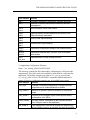
File / Module
Content
api.h
CANopen Application Programming Interface definitions
tsk.h
Definition of functions and tasks controlled by the task
management
cco.h
cco.c
MicroCANopen Classic core module
oda.h
oda.c
Object Dictionary Access implements the access to the
Object Dictionary data tables
sdo.h
sdo.c
Service Data Object handling
pdo.h
pdo.c
Process Data Object handling
nvol.h
nvol.c
Implements configuration storage in non-volatile memory
xnmt.h
xnmt.c
Implements extended NMT services, such as heartbeat
consumption
lss.h
lss_slv.c
Implementation of Layer Settings Services
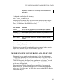
2.) Application Configuration Directory
Name: ../src_usercfg_APPLICATIONNAME
This directory contains the files and modules configuring the CANopen node
implemented. These files need to be modified or generated for each particular
application. The default examples provided are src_usercfg_mynode and
src_usercfg_ds401 a Device Profile DS401 compatible implementation of a
generic I/O device. Additional examples may be available upon request.
File / Module
Content
cco_cfg.h
CANopen functionality configuration; CANopen features
supported can be enabled/disabled via #define
img_NAME.h
Definition of symbolic offsets for locations in the process
image
uod_NAME.c
Contents of the CANopen Object Dictionary and default
configuration of the PDOs
ccocb_NAME.
c
Call-back module, implements all the call-back functions
from CANopen stack to the application
tsk_NAME.c
Task management module that controls with which priority
which CANopen function is executed; this must be modified
9
THE MICROCANOPEN CLASSIC PROTCOL STACK
depending on the RTOS or interrupt structure used in the
application
3.) Chip and Compiler Specific Directory
Name: ../CHIP_COMPILER_src
This directory contains the source files that are chip architecture and compiler
specific. This includes all handlers for hardware peripherals of a chip (CAN,
Timer, NVOL-Memory like EEPROM or Flash).
File / Module
Content
ccohw.h
ccohw_CHIP.c
Driver for CAN peripheral or interface and timer handling;
also implement CAN receive interrupt and timer interrupt
nvolhw.h
nvolhw_CHIP.
c
Non-volatile memory access functions; only needed if NVOL
support is enabled
main_CHIP.c
Main module for stand-alone operation of MicroCANopen
Classic
4.) Compiler Management Directory
Name: ../CHIP_COMPILER
This directory contains all files (and subdirectories) generated by the compiler:
project files, make files, object files, executables, maps, etc.
MYNODE EXAMPLE CONFIGURATION AND APPLICATION
This manual uses the simple example application MyNode that implements a
CANopen node producing two analog temperature values Temp1 and Temp2 of
type INTEGER16 and two digital values Butttons1 and Buttons2 of type
UNSIGNED8 reporting the state of some input buttons and switches. The node
consumes two digital values LEDs1 and LEDs2 of type UNSIGNED8 used to
switch some indication lights.
This example uses TPDO1 (Transmit Process Data Object 1) to transmit the
button values every 100 milliseconds and TPDO2 to transmit the temperature
values every 250 milliseconds. The LED values are received in RPDO1 (Receive
Process Data Object 1).
10
THE MICROCANOPEN CLASSIC PROTCOL STACK
APPLICATION INTERFACE
Both shared data memory and function calls are used to implement an interface
between MicroCANopen Classic the application program. A process image (array
of bytes) is used as shared memory that can be accessed from both
MicroCANopen Classic as well as from the application program. The process
image contains all process data variables that are communicated via CANopen, as
well as application specific configuration data. Several access functions are
provided to allow the application program to read or write data from or to the
process image.
THE PROCESS IMAGE
In order to offer a generic method for addressing and exchanging the data
communicated via CANopen, the data is organized into a process image which is
implemented as an array of bytes. The maximum length PROC_IMG_SIZE of that
array is either FFh or FFFFh depending on the maximum value defined for
TABLE_MAXSIZE and the type defined for TTABLE_SIZE in file cco_cfg.h.
A single variable of the process image can be addressed by specifying an offset
and a length. The offset specifies where in the process image the first byte of a
variable is stored and the length specifies how many bytes are used to store the
variable. The offset may have a value from 0 to TABLE_MAXSIZE-1. Using an
offset of TABLE_MAXSIZE indicates that the offset is invalid or unused.
If numeric values are stored in multiple byte variables, then the default format is
CANopen compatible: Little Endian – the lower bytes are stored at the lower
offset.
If required by the application, the data storage format in the process image can be
changed to Big Endian by setting the define PROCIMG_LITTLEENDIAN in file
ccohw.h to zero.
CONFIGURATION OF THE PROCESS IMAGE
Where exactly which variable is located in the process image is part of the
CANopen node configuration process that needs to be done by the
designer/programmer of the CANopen node. The CANopen configuration process
also includes assigning an Object Dictionary Index and Subindex to each variable
and to configure the PDOs (Process Data Objects) containing one or multiple
process data variables.
To simplify accessing the process image and to allow for easy re-configuration of
process images, it is recommended to use #define statements to define the offsets
to the individual variables in the process image. These should be defined in the
file img_xxx.h that can be included to all code modules requiring access to the
process image.
11
THE MICROCANOPEN CLASSIC PROTCOL STACK
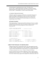
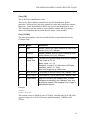
Besides the process data the process image also stores some vital configuration
and system data like the CANopen error register or the heartbeat time. The
following system entries must be provided in the process image:
#define Name
Bytes
Object Dictionary Entry
PIO_HEARTBEAT
2
[1017h,00h]
Producer Heartbeat Time
PIO_ERROR_REGISTER
1
[1001h,00h]
Error Register
PIO_RPDO_DUMMY
4
[0001h-0007h,00h]
Data types for dummy mapping
PIO_GUARDTIME
2
[100Ch,00h]
Node Guard Time
PIO_GUARDFACTOR
1
[100Dh,00h]
Node Guard Life Time Factor
PIO_HBCONSUMER_BASE
4*Cons [1016h,xxh]
Heartbeat Consumer
PIO_EMCYCONSUMER_BASE 4*Cons [1028h,xxh]
Emergency Consumer
Note 1: Dummy mapping is used when not all data bytes contained in a
process data message received are needed. All unused/unwanted bytes will
be written to the area reserved for “dummy mapping”.
HEARTBEAT CONSUMER FUNCTIONALITY
If heartbeat consumption [1016h,xx] is implemented, the Object Dictionary
entries for the consumer are also stored in the process image. The required storage
format is a 4-byte value for each heartbeat consumer entry. The define value (in
file img_xxx.h) PIO_HBCONSUMER_BASE defines the base address/offset of
where this array is stored in the process image. The define value
NR_OF_HB_CONSUMERS defines the number of heartbeat consumer channels
provided. The required storage space in the process image is 4 times
NR_OF_HB_CONSUMERS. A value of 0 turns off this feature.
EMERGENCY CONSUMER FUNCTIONALITY
If emergency consumption [1028h,xx] is implemented, the Object Dictionary
entries for the consumer are also stored in the process image. The required storage
format is a 4-byte value for each emergency consumer entry. The define value (in
file img_xxx.h) PIO_EMCYCONSUMER_BASE defines the base address/offset
12
THE MICROCANOPEN CLASSIC PROTCOL STACK
of where this array is stored in the process image. The define value
NR_OF_EMCY_CONSUMERS defines the number of heartbeat consumer
channels provided. The required storage space in the process image is 4 times
NR_OF_EMCY_CONSUMERS. A value of 0 turns off this feature.
ACCESSING THE PROCESS IMAGE
Although an application program could directly access the data in the process
image, it is strongly recommended to use the access functions provided by
MicroCANopen Classic. The functions CCO_Read_Process_Data() and
CCO_Write_Process_Data() ensure both data integrity and consistency by
implementing resource locking.
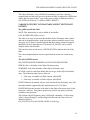
MYNODE EXAMPLE
When implementing a CANopen node with MicroCANopen Classic the variables
communicated via the network need to be assigned to the process image. For the
MyNode example the following assignment is chosen (defined in file
img_mynode.h):
// Size of process image
#define PROC_IMG_SIZE 16
// reserve 16 bytes
// Definition of Process Image Offsets (PIO)
#define PIO_Temp1 0
// 1 word at offset 0
#define PIO_Temp2 2
// 1 word at offset 2
#define PIO_Buttons1 4
// 1 byte at offset 4
#define PIO_Buttons2 5
// 1 byte at offset 5
#define PIO_LEDs1 6
// 1 byte at offset 6
#define PIO_LEDs2 7
// 1 byte at offset 7
// System Entries
#define PIO_RPDO_DUMMY 8
#define PIO_HEARTBEAT 12
#define PIO_ERROR_REGISTER 14
// 4 bytes at offset 8
// 2 bytes at offset 12
// 1 byte at offset 14
OBJECT DICTIONARY CONFIGURATION
Although working with CANopen EDS and DCF files is the standard procedure
for many CANopen configuration tools, many embedded CANopen nodes require
a specific default configuration that a node should use if not configured through a
CANopen configuration tool or by a CANopen Configuration Manager.
In MicroCANopen Classic the default configuration is setup via tables typically
implemented in a file called uod_xxx.c (“UOD” stands for User Object Dictionary
file). If non-volatile memory support and configurationis enabled, these tables can
13
THE MICROCANOPEN CLASSIC PROTCOL STACK
be stored in non-volatile memory such as EEPROM or FLASH memory allowing
for an implementation that can easily be configured via a configuration file.
The tables gODConstTable and gODRWTable define the contents of the Object
Dictionary. The tables gRPDOCom, gTPDOCom, gRPDOMap and gTPDOMap
define the PDO communication and mapping parameters.
CONSTANT EXPEDITED OBJECT DICTIONARY ENTRIES
The gODConstTable table
The table gODConstTable is an array of bytes that contains a list of SDO
responses for SDO requests to constant, read-only entries in the object dictionary
limited to 4 bytes or less. Typically these contain the [1000,00] Device Type
entry, the [1018,xx] Identity Objects and some “Number of Entries” type entries
with a Subindex of zero.
Each entry in this list has 8 bytes that directly contain the 8 bytes used in a CAN
message with an expedited SDO response to a read (upload) request.
The macros SDO_REPLY and SDO_REPLY4 are provided to ease the generation
of the 8-byte entries.
The last entry must be 8 times 0xFF to indicate the end of the table.
The current implementation does not require that the entries are sorted in any
way.
The SDO_REPLY macro
This macro generates the 8-byte SDO response required for a read (upload)
request from an Object Dictionary entry with a constant entry.
SDO_REPLY(INDEX,SUBINDEX,LENGTH,VALUE)
INDEX is the 16-bit Index of the Object Dictionary entry.
SUBINDEX is the 8-bit Subindex of the Object Dictionary entry.
LENGTH is the length of the Object Dictionary entry in bytes and must be in the
range of 1 to 4.
VALUE is the value of the Object Dictionary entry. It must be defined as a 32-bit
value even if LENGTH is less than 4-bytes. In that case the unused bytes must be
set to zero.
The Object Dictionary entry [1000h,00h] with a value of 00030191h can be
generated by:
SDO_REPLY(0x1000,0x00,4,0x00030191L),
The SDO_REPLY4 macro
This macro generates the 8-byte SDO response required for a read (upload)
request from an Object Dictionary entry with a constant entry of 4 bytes with an
14
THE MICROCANOPEN CLASSIC PROTCOL STACK
ASCII interpretation. This simplifies the generation of 32-bit Object Dictionary
entries whose contents is not interpreted as a 32-bit value but as 4 characters.
SDO_REPLY4(INDEX,SUBINDEX,CHAR1,CHAR2,CHAR3,CHAR4)
INDEX is the 16-bit Index of the Object Dictionary entry.
SUBINDEX is the 8-bit Subindex of the Object Dictionary entry.
CHAR1 through CHAR4 contain the 4 characters stored at this Object Dictionary
entry.
VARIABLE EXPEDITED AND MAPPABLE OBJECT DICTIONARY
ENTRIES
The gODTable table
This table is an array of structures that defines Object Dictionary entries whose
data is located in the process image and that can be mapped into PDOs (Process
Data Objects). All Object Dictionary entries that can be mapped to a PDO or need
to be shared with the application via the process image must be defined in this
table. The macro OD_ENTRY can be used to simplify entries into this table.
The last entry must use the macro LASTODENTRY to indicate the end of the
table.
The current implementation does not require that the entries are sorted in any
way.
The OD_ENTRY macro
OD_ENTRY(INDEX,SUBINDEX,TLINFO,OFFSET)
INDEX is the 16-bit Index of the Object Dictionary entry.
SUBINDEX is the 8-bit Subindex of the Object Dictionary entry.
TLINFO is an 8-bit value that defines access type and length of the Object
Dictionary entry. The TLINFO value can be generated by adding up the length of
the Object Dictionary entry (must be in the range of 1 to 4) and the following
status bits:
•
if the entry is readable via SDO requests, add ODRD
•
if the entry is writable via SDO requests, add ODWR
•
if the entry can be mapped to a TPDO, add RMAP
•
if the entry can be mapped to a RPDO, add WMAP
Note that an entry can be both readable and writable, but it may only be mappable
in one direction (either RMAP or WMAP, but not both).
OFFSET defines the location of the data for this Object Dictionary entry in the
process image. If set to 3, the data is located starting at the 4th byte in the process
image.
15
THE MICROCANOPEN CLASSIC PROTCOL STACK
The Object Dictionary entry [6200h,01h] containing a one byte value that
supports both read and write accesses but that can only be mapped to a RPDO and
whose data is located in the 8th byte of the process image is defined as follows:
OD_ENTRY(0x6200,0x01,1+ODRD+ODWR+WMAP,7),
VARIABLE GENERIC NON-MAPPABLE OBJECT DICTIONARY
ENTRIES
The gODGenericTable table
NOTE: This functionality is only available if the #define
USE_SEGMENTED_SDO is set to 1.
This table is an array of structures that defines Object Dictionary entries whose
data can be located anywhere in the processors memory and that can be of any
size up to 65,535 bytes. It should be noted that these entries cannot be mapped
into PDOs (Process Data Objects). The macro OD_GENTRY can be used to
simplify entries into this table.
The last entry must use the macro LASTODGENTRY to indicate the end of the
table.
The current implementation does not require that the entries are sorted in any
way.
The OD_GENTRY macro
OD_GENTRY(INDEX,SUBINDEX,ACCESS,LENGTH,POINTER)
INDEX is the 16-bit Index of the Object Dictionary entry.
SUBINDEX is the 8-bit Subindex of the Object Dictionary entry.
ACCESS is an 8-bit value that defines the access type of the Object Dictionary
entry. Tthe following status bits are allowed:
•
if the entry is readable via SDO requests, add ODRD
•
if the entry is writable via SDO requests, add ODWR
LENGTH defines the number of bytes stored in this Object Dictionary entry. The
maximum number supported by this implementation is 65,535 bytes.
POINTER defines the location of the data for this Object Dictionary entry in the
processor’s memory. This generic pointer may point to any memory location
available to the processor.
The fictitious Object Dictionary entry [2010h,01h] containing a 16 byte string
called “char myString[16]” and that supports both read and write accesses is
defined as follows:
OD_GENTRY(0x2010,0x01ODRD+ODWR,16,myString),
16
THE MICROCANOPEN CLASSIC PROTCOL STACK
RPDO COMMUNICATION PARAMETERS
The gRPDOCom table
This table is an array of structures containing the communication parameters for
the RPDOs (Receive Process Data Objects). The number of entries in this table
must match the global #define settings for NR_OF_RPDOS. The first entry in the
table is used to define the parameters for RPDO1, the second for RPDO2 and so
on. Each table entry consists of the COB-ID and the transmission type used for
the RPDO.
The macro RPDO_COM_ENTRY is provided to simplify the entries made into the
table.
The RPDO_COM_ENTRY macro
RPDO_COM_ENTRY(CANID,TTYPE,DUMMY,DUMMY)
The CANID specifies the default 11-bit CAN message ID used by this RPDO. If
set to zero, the default from the pre-defined connection set of CANopen is used.
TTYPE is a byte with the CANopen RPDO transmission type. Typically a default
of FEh (manufacturer specific) or FFh (device profile specific) is used.
The DUMMY values are currently not used, leave at zero.
Note: MicroCANopen Classic currently does not support RTR transmission or 29bit CAN message identifiers.
TPDO COMMUNICATION PARAMETERS
The gTPDOCom table
This table is an array of structures containing the communication parameters for
the TPDOs (Transmit Process Data Objects). The number of entries in this table
must match the global #define settings for NR_OF_TPDOS. The first entry in the
table is used to define the parameters for TPDO1, the second for TPDO2 and so
on. Each table entry consists of the COB-ID and the transmission type used for
the TPDO.
The macro TPDO_COM_ENTRY is provided to simplify the entries made into the
table.
The TPDO_COM_ENTRY macro
TPDO_COM_ENTRY(CANID,TTYPE,INHIBITT,EVENTT)
The CANID specifies the default 11-bit CAN message ID used by this TPDO. If
set to zero, the default from the pre-defined connection set of CANopen is used.
TTYPE is a byte with the CANopen TPDO transmission type. Typically a default
of FEh (manufacturer specific) or FFh (device profile specific) is used.
17
THE MICROCANOPEN CLASSIC PROTCOL STACK
INHIBITT defines the default inhibit time used by the corresponding TPDO. The
inhibit time is defined in multiples of 100 microseconds and can be in the range
from zero to 65535.
EVENTT defines the default event time used by the corresponding TPDO. The
event time is defined in multiples of milliseconds and can be in the range from
zero to 65535.
Note: MicroCANopen Classic currently does not support RTR transmission or 29bit CAN message identifiers.
PDO MAPPING PARAMETERS
The gRPDOMap and gTPDOMap tables
For each PDO, these tables contain the mapping parameters. The number of
entries in each table must match the global #define settings for NR_OF_RPDOS
and NR_OF_TPDOS.
For each PDO the table contains 9 entries – the number of items/variables mapped
and then 8 entries, allowing for a maximum of 8 Object Dictionary entries being
mapped into the PDO. Unused entries must have all bits set to indicate that these
entries are unused.
A single entry consists of an index into the gODTable table. A value of zero
indicates that the first entry of the array gODTable is mapped to the PDO. A value
of 3 indicates that the fourth entry of the array gODTable is mapped to the PDO.
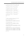
MYNODE CONFIGURATION EXAMPLE
For the MyNode example, the file odu_mynode.c contains:
#include “cco.h”
#include “img_mynode.h”
// implement the process image
UNSIGNED8 gProcImg[PROC_IMG_SIZE];
// OBJECT DICTIONARY TABLE FOR CONST, READ-ONLY ENTRIES
BYTE gODConstTable[] = {
// [1000h,00]: Device Type
SDO_REPLY(0x1000, 0x00, 4, OD_DEVICE_TYPE),
// [1018h,00]: Identity Object, Number of Entries = 4
SDO_REPLY(0x1018, 0x00, 1, 0x00000004L),
// [1018h,01]: Identity Object, Vendor ID
SDO_REPLY(0x1018, 0x01, 4, OD_VENDOR_ID),
18
THE MICROCANOPEN CLASSIC PROTCOL STACK
// [1018h,02]: Identity Object, Product Code
SDO_REPLY(0x1018, 0x02, 4, OD_PRODUCT_CODE),
// [1018h,03]: Identity Object, Revision
SDO_REPLY(0x1018, 0x03, 4, OD_REVISION),
// [1018h,04]: Identity Object, Serial
SDO_REPLY(0x1018, 0x04, 4, OD_SERIAL),
// [6000h,00]: Number of digital IN bytes: 2
SDO_REPLY(0x6000, 0x00, 1, 0x00000002L),
// [6200h,00]: Number of digital OUT bytes: 2
SDO_REPLY(0x6200, 0x00, 1, 0x00000002L),
// [6401h,00]: Number of analog IN words: 2
SDO_REPLY(0x6401, 0x00, 1, 0x00000002L),
// Last Entry
0xFF
};
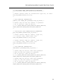
// OBJECT DICTIONARY TABLE FOR RD/WR ENTRIES
OD_PROCESS_DATA_ENTRY gODRWTable[] =
{
// 0-1: Digitial Inputs
OD_ENTRY(0x6000,0x01,1+ODRD+RMAP,PIO_Buttons1),
OD_ENTRY(0x6000,0x02,1+ODRD+RMAP,PIO_Buttons2),
// 2-3: Analog Inputs
OD_ENTRY(0x6401,0x01,2+ODRD+RMAP,PIO_Temp1),
OD_ENTRY(0x6401,0x02,2+ODRD+RMAP,PIO_Temp2),
// 4-5: Digital Outputs
OD_ENTRY(0x6200,0x01,1+ODRD+ODWR+WMAP,PIO_LEDs1),
OD_ENTRY(0x6200,0x02,1+ODRD+ODWR+WMAP,PIO_LEDs2),
// System entries
OD_ENTRY(0x1001,0x00,1+ODRD,PIO_ERROR_REGISTER),
OD_ENTRY(0x1017,0x00,2+ODRD+ODWR,PIO_HEARTBEAT),
OD_ENTRY(0x0005,0x00,1+ODWR+WMAP,PIO_RPDO_DUMMY),
OD_ENTRY(0x0006,0x00,2+ODWR+WMAP,PIO_RPDO_DUMMY),
OD_ENTRY(0x0007,0x00,4+ODWR+WMAP,PIO_RPDO_DUMMY),
LASTODENTRY
};
19
THE MICROCANOPEN CLASSIC PROTCOL STACK
// INITIALIZE RPDO COMMUNICATION PARAMETERS
PDO_COM_PARAM TMEM_FAR gRPDOCom[NR_OF_RPDOS] =
{
// RPDO1: Default node ID, Transmission Type 255, no timer
PDO_COM_ENTRY(0x000,255,0,0),
};
// RPDO MAPPING INFORMATION:
TTABLE_SIZE TMEM_FAR gRPDOMap[9*NR_OF_RPDOS] =
{
// RPDO1: map 5th and 6th element of gODTable
// Nr of entries + Map OD entries
2, 4,5,TABLE_MAXSIZE,TABLE_MAXSIZE,TABLE_MAXSIZE,
TABLE_MAXSIZE,TABLE_MAXSIZE,TABLE_MAXSIZE
};
// INITIALIZE TPDO COMMUNICATION PARAMETERS
PDO_COM_PARAM gTPDOCom[NR_OF_TPDOS] =
{
// TPDO1: Default CAN-ID, enable, ttype 255,
// 0 inhibit time, 100ms event time
TPDO_COM_ENTRY(0x000,0,255,0,100),
// TPDO2: Default CAN-ID, enable, ttype 255,
// 0 inhibit time, 250ms event time
TPDO_COM_ENTRY(0x000,0,255,0,250)
};
// TPDO MAPPING INFORMATION:
UNSIGNED16 gTPDOMap[8*NR_OF_TPDOS] =
{
// TPDO1: Map OD entries from table gODTable
// map 3rd and 4th element of gODTable
// Nr of entries + Map OD entries
2, 2,3,TABLE_MAXSIZE,TABLE_MAXSIZE,TABLE_MAXSIZE,
TABLE_MAXSIZE,TABLE_MAXSIZE,TABLE_MAXSIZE,
// TPDO2: Map OD entries from table gODTable
// map 1st and 2nd element of gODTable
// Nr of entries + Map OD entries
2, 0,1,TABLE_MAXSIZE,TABLE_MAXSIZE,TABLE_MAXSIZE,
TABLE_MAXSIZE,TABLE_MAXSIZE,TABLE_MAXSIZE};
20
THE MICROCANOPEN CLASSIC PROTCOL STACK
CANOPEN API FUNCTIONS
This section lists all the functions that can be called by the application program.
The CCO_Init_CANopen function
The CCO_Init_CANopen function (re-)initializes the CANopen protocol stack. It
needs to be called during system initialization. It may also be called tore-initialize
the CANopen stack, for example to force a reset of the CANopen communication
task(s).
Called
UNSIGNED8 CCO_Init_CANopen (UNSIGNED8 bps, UNSIGNED8 nodeid);
UNSIGNED8 BPS; // desired CAN bit rate
UNSIGNED8 NODEID; // desired CANopen node ID
UNSIGNED8 STATUS; // return value
STATUS=CCO_Init_CANopen(BPS,NODEID);
Passed
BPS selects the desired CAN bit rate to be used. The following values are
allowed:
0
use default or pre-defined bit rate
1
use 10 kbps
2
use 20 kbps
3
use 50 kbps
4
use 125 kbps
5
use 250 kbps
6
use 500 kbps
7
use 800 kbps
8
use 1,000 kbps
NODEID is the CANopen node ID to be used by this CANopen node. The
allowed value range is 0 to 127. If 0 is selected, MicroCANopen Classic will use
the default or pre-configured node ID.
Returned
STATUS is set to TRUE if the function executed successfully, else it is set to
FALSE.
The CCO_Read_Process_Data function
This function is used to read data from the process image.
21
THE MICROCANOPEN CLASSIC PROTCOL STACK
Called
UNSIGNED16 CCO_Read_Process_Data (UNSIGNED8 *pDest, UNSIGNED8
length, UNSIGNED16 offset);
UNSIGNED8 PDEST; // destination pointer to where the data is copied
UNSIGNED8 LENGTH; // length of the data
UNSIGNED16 OFFSET; // offset to data location in the process image
UNSIGNED8 NROFBYTES; // return value, number of bytes actually copied
NROFBYTES=CCO_READ_PROCESS_DATA(PDEST,LENGTH,OFFSET);
Passed
PDEST is a destination pointer to the location to which the requested process data
should be copied. The caller must ensure that the buffer at the destination
locations is large enough to hold the number of data bytes requested.
LENGTH defines the number of data bytes requested.
OFFSET defines the location of the requested data within the process image. If set
to zero, the data is located at the first byte of the process image.
Returned
NROFBYTES contains the number of bytes actually copied to the destination
buffer. If zero, no data was copied because the requested offset was out of range.
The CCO_Write_Process_Data function
This function is used to write data to the process image.
Called
UNSIGNED16 CCO_Write_Process_Data (UNSIGNED16 offset, UNSIGNED8
length, UNSIGNED8 *pSource);
UNSIGNED16 OFFSET; // offset to data location in the process image
UNSIGNED8 LENGTH; // length of the data
UNSIGNED8 PSOURCE; // source pointer from which the data is copied
UNSIGNED8 NROFBYTES; // return value, number of bytes actually copied
NROFBYTES=CCO_WRITE_PROCESS_DATA(OFFSET,LENGTH,PSOURC
E);
22
THE MICROCANOPEN CLASSIC PROTCOL STACK
Passed
OFFSET defines the location of the target data within the process image. If set to
zero, the data is located at the first byte of the process image.
LENGTH defines the number of data bytes to be copied.
PSOURCE is a source pointer to the location from which the process data should
be copied.
Returned
NROFBYTES contains the number of bytes actually copied to the process image.
If zero, no data was copied because the requested offset was out of range.
CANOPEN API CALL-BACK FUNCTIONS
This section lists all call-back functions that can be called by the CANopen
protocol stack. They indicate important CANopen events to the application.
The CCOCB_NMT_Change function
This function is called whenever the CANopen protocol stack receives the NMT
(Network Management) Master message, typically requesting a change in the
operating state.
Called
void CCOCB_NMT_Change (UNSIGNED8 NMTState);
UNSIGNED8 NMTSTATE; // the CANopen NMT state
CCOCB_NMT_STATE(NMTSTATE);
Passed
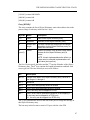
The value for NMTSTATE indicates which NMT state was requested by the
NMT Master. It can be one of the following values:
00h
Initializing (sent after receiving the ‘I’ command)
04h
CANopen NMT state “stopped” entered
05h
CANopen NMT state “operational” entered
7Fh
CANopen NMT state “pre-operational” entered
81h
An NMT Master message was received requesting to reset the entire
CANopen node, the application should reset itself
82h
An NMT Master message was received requesting to reset the CAN
communication interface, the application should re-initialize the CANopen
protocol stack
Returned
Nothing.
23
THE MICROCANOPEN CLASSIC PROTCOL STACK
The CCOCB _Data_Received function
This function is called after MicroCANopen Classic has copied data to the
process image. This function is called for both processed RPDOs as well as
executed SDO write requests to process data.
Called
void CCOCB_Data_Received (UNSIGNED8 length, TTABLE_SIZE offset);
CCOCB_Data_Received (LENGTH, OFFSET);
Passed
The value for LENGTH is the size of the mapped entry in bytes, as specified in
the Object Dictionary table.
The OFFSET value is the offset into the Process Image array for the mapped
entry, as specified in the Object Dictionary table.
Returned
Nothing.
24
THE MICROCANOPEN CLASSIC PROTCOL STACK
The CCOCB_SYNC_Received function
This function signals the receipt of the CANopen SYNC message for this device.
Synchronous RPDO data previously received and copied to the process image
may now be applied to the application. Per default configuration (see section
TASK MANAGEMENT, tsk_NAME.c) synchronous TPDO data transmission
will be triggered after execution of this call-back function.
Called
void CCOCB_SYNC_Received (void);
CCOCB_SYNC_Received();
Passed
Nothing.
Returned
Nothing.
The CCOCB_EMCY_Received function
This function is only available when emergency consumer functionality is
enabled. It is then called upon reception of an emergency, if the emergency is
configured for reception (via [1028h,00h]).
Called
void CCOCB_EMCY_Received (UNSIGNED8 channel, UNSIGNED8 *pErr);
UNSIGNED8 CHANNEL; // the emergency consumer channel number
UNSIGNED8 *PERR; // a pointer to the 8 data bytes of the emergency message
CCOCB_EMCY_Received (CHANNEL,PERR);
Passed
The value for CHANNEL is in the range of 1 to NR_OF_EMCY_CONSUMERS
and identifies the consumer channel on which this emergency was received
The PERR pointer points to an array of 8 UNSIGNED8 values containing the 8
data bytes of the emergency message.
Returned
Nothing.
The CCOCB_Fatal_Error function
This indication signals the application that the CANopen stack ran into a fatal
error situation and needs to be reset or re-initialized to start operation again.
Called
25
THE MICROCANOPEN CLASSIC PROTCOL STACK
void CCOCB_Fatal_Error(UNSIGNED16 errorcode);
UNSIGNED16 ERRORCODE; // 16-bit error code
CCOCB_Fatal_Error(ERRORCODE);
Passed
The ERRORCODE is an internal 16-bit error code.
Returned
Nothing.
The CCOCB_TX_Error function
This indication signals the application that the CANopen stack ran into a CAN
message transmit overrun situation A message could not be added to the transmit
buffer as the transmit buffer was full.
Called
void CCOCB_TX_Error(UNSIGNED16 ErrCode);
UNSIGNED16 ERRCODE; // 16-bit error code
CCOCB_TX_Error(ERRCODE);
Passed
The ERRCODE indicates the type of CAN message that could not be transmitted:
TXLOST_PDO, TXLOST_SDO or TXLOST_HB (TPSO, SDO or heartbeat).
Returned
Nothing.
The CCOCB_SDO_Response_Received function for SDO Clients
This function is only available if SDO Clients are enabled (by setting
NR_OF_SDO_CLIENTS to a value other than zero). It notifies the application of
the result of a previously sent SDO request.
Called
void CCOCB_SDO_Response_Received (UNSIGNED8 channel, UNSIGNED8
sdoerr);
UNSIGNED8 channel; // The SDO channel number for which this is a reponse
UNSIGNED8 sdoerr; // SDO error/ok/status value
CCOCB_SDO_Response_Received (CHANNEL,SDOERR);
26
THE MICROCANOPEN CLASSIC PROTCOL STACK
Passed
The CHANNEL number identifies the SDO Client channel for which this is a
response. This is a channel for which an SDO Request was sent previously.
The SDOERR value returned can be one of the following:
SDOERR_WRITEOK
The previously made write attempt is confirmed
SDOERR_READOK
The previously made read attempt is completed,
the data is now available
SDOERR_ABORT
An SDO Abort message was received
SDOERR_UNKNOWN
The response received is unknown
SDOERR_TIMEOUT
The previously made access attempt timed out,
the mode addressed did not reply
Returned
Nothing.
The CCOCB_RPDO_Received function
This function notifies the application of an RPDO received..
Called
void CCOCB_RPDO_Received (UNSIGNED16 PDONr, UNSIGNED8 len,
UNSIGNED8 *pData);
UNSIGNED16 PDONr; // The RPDO number in range from 1 to 512
UNSIGNED8 len; // Length of RPDO (1 to 8 bytes)
UNSIGNED8 *pData; // Pointer to the PDO data received
CCOCB_RPDO_Received (PDONR,LEN,PDATA);
Passed
The PDONR is in the range of 1 to 512 and indicates the PDO number of the
received RPDO.
The LEN value is in the range of 1 to 8, depending on the length of the data
received.
PDATA is a pointer to the data received.
Returned
Nothing.
27
THE MICROCANOPEN CLASSIC PROTCOL STACK
CANOPEN API EXTENDED FUNCTIONS
This section lists all functions considered extended functionality. They typically
require that certain define values are set to enable the functionality requested.
The XNMT_Transmit_NMT_Msg function
This function generates the NMT master message. Note that only the CANopen
NMT Master is allowed to transmit this message.
Called
UNSIGNED8 XNMT_Transmit_NMT_Msg (UNSIGNED8 nmt_cmd,
UNSIGNED8 node_id);
UNSIGNED8 nmt_cmd; // the CANopen NMT command
UNSIGNED8 node_id; // the CANopen node id of the receiving node
XNMT_Transmit_NMT_Msg(NMTCMD,NODEID);
Passed
The value for NMTCMD indicates which NMT state was requested by the NMT
Master. The following define values can be used
NMT_MSG_OP
0x01 // Go into operational state
NMT_MSG_STOP
0x02 // Go into operational state
NMT_MSG_PREOP
0x80 // Go into preoperational state
NMT_MSG_RNODE
0x81 // Reset Node
NMT_MSG_RAPP
0x82 // Reset Application
The value NODEID can be set to zero if this command is for ALL CANopen
slaves on the netork or it can be set to an individual node ID (in the range of 1 to
127) to only address the command to a single node.
Returned
TRUE, if the message was queued for transmission.
FALSE, if the transmit queue is full and the message could not be added.
28
THE MICROCANOPEN CLASSIC PROTCOL STACK
The XNMT_Process_HB_Check function
When heartbeat consumer functionality is enabled, this function verifies if a
timeout occurred with any of the heartbeats consumed.
Called
UNSIGNED8 XNMT_Process_HB_Check (VOID);
XNMT_Process_HB_Check(VOID);
Passed
Nothing.
Returned
Zero, if no heartbeat timeout was detected.
If unequal zero, the return value is the node ID number of the node whose
heartbeat was lost.
The XNMT_Init_SDO_Client function
This function initializes a single SDO Client channel. It must be called before the
channel can be used. This function may also be called again if an existing SDO
channel should be re-configured.
Called
UNSIGNED8 XNMT_Init_SDO_Client (UNSIGNED8 channel, UNSIGNED32
canid_request, UNSIGNED32 canid_response);
UNSIGNED8 channel; // SDO channel number in range of 1 to
NR_OF_SDO_CLIENTS
UNSIGNED32 canid_request; // CAN message ID used for the SDO request
UNSIGNED32 canid_response; // CAN message ID used for the SDO response
UNSIGNED8 XNMT_Init_SDO_Client (UNSIGNED8 channel, UNSIGNED32
canid_request, UNSIGNED32 canid_response);
XNMT_Init_SDO_Client (CHANNEL,CANIDREQ,CANIDRESP);
29
THE MICROCANOPEN CLASSIC PROTCOL STACK
Passed
The value for CHANNEL indicates the SDO Client channel to be (re-)initialized.
It must be in the range of 1 to NR_OF_SDO_CLIENTS.
CANIDREQ specifies the CAN message ID used for sending SDO requests. To
address the default SDO channel of a specific node this must be set to 600h plus
the node ID of the addressed node.
CANIDRESP specifies the CAN message ID used for receiving the SDO
responses. To receive the responses from a default SDO channel of a specific
node this must be set to 580h plus the node ID of the addressed node.
Returned
TRUE, if the channel initialization was successful.
FALSE, if the channel initialization failed.
The XNMT_SDO_Client_Read function
This function transmits an SDO Read (Upload) Request using one of the SDO
client channels. The channel must have been previously initialized with a call to
XNMT_Init_SDO_Client. The function does NOT wait for the response. If a SDO
response comes in, the application is informed via the call-back function
CCOCB_SDO_Response_Received that the data is now available.
Called
UNSIGNED8 XNMT_SDO_Client_Read (UNSIGNED8 channel, UNSIGNED16
index, UNSIGNED8 subindex, UNSIGNED8 **len, UNSIGNED8 **dat);
UNSIGNED8 channel; // SDO channel number
UNSIGNED16 index; // Object Dictionary Index to read
UNSIGNED8 subindex; // Object Dictionary Subindex to read
UNSIGNED8 **len; // Return: Ptr to length
UNSIGNED8 **dat; // Return: Ptr to data
XNMT_SDO_Client_Read (CHANNEL,INDEX,SUBINDEX,LEN,DAT);
30
THE MICROCANOPEN CLASSIC PROTCOL STACK
Passed
CHANNEL defines the SDO Client channel used for the request and must be in
the range from 1 to NR_OF_SDO_CLIENTS.
The values INDEX and SUBINDEX specify the Object Dictionary entry that is to
be read.
LEN and DAT are return values. The addresses passed in LEN and DAT will be
written to. After the function call these locations will contain pointers to a length
and a data value. Once a SDO Response is received, the length will indicate the
length of the data received (maximum of 4 bytes in current implementation) and
data will contain the data received.
NOTE: The data is NOT available until the call-back function
CCOCB_SDO_Response_Received is called with the appropriate parameters!
Returned
TRUE, if the SDO Request was placed into the transmit queue.
FALSE, if the transmit queue is full and the SDO request could not be queued for
transmission.
The XNMT_SDO_Client_Write_Expedited function
This function transmits an Expedited SDO Write (Download) Request using one
of the SDO client channels. The channel must have been previously initialized
with a call to XNMT_Init_SDO_Client. The function does NOT wait for the
response. If a SDO response comes in, the application is informed via the callback function CCOCB_SDO_Response_Received that the access was confirmed
or denied.
Called
UNSIGNED8 XNMT_SDO_Client_Write_Expedited(UNSIGNED8 channel,
UNSIGNED16 index, UNSIGNED8 subindex, UNSIGNED8 len, UNSIGNED8
*dat);
UNSIGNED8 channel; // SDO channel number
UNSIGNED16 index; // Object Dictionary Index to read
UNSIGNED8 subindex; // Object Dictionary Subindex to read
UNSIGNED8 len; // Length of data
UNSIGNED8 *dat; // Pointer to data
XNMT_SDO_Client_Write_Expedited
(CHANNEL,INDEX,SUBINDEX,LEN,DAT);
31
THE MICROCANOPEN CLASSIC PROTCOL STACK
Passed
CHANNEL defines the SDO Client channel used for the request and must be in
the range from 1 to NR_OF_SDO_CLIENTS.
The values INDEX and SUBINDEX specify the Object Dictionary entry that is to
be written to.
LEN and DAT specify the data that should be written to the selected Object
Dictionary entry. LEN may be in the range of 1 to 4 and DAT accordingly points
to 1 to 4 data bytes.
Returned
TRUE, if the SDO Request was placed into the transmit queue.
FALSE, if the transmit queue is full and the SDO request could not be queued for
transmission.
32
THE MICROCANOPEN CLASSIC PROTCOL STACK
CANOPEN CODE CONFIGURATION
The file cco_cfg.h contains the #define settings that configure and enable specific
CANopen code functionality. The settings in ccohw.h define hardware related
settings.
TABLE SIZE SETTINGS OF CCO_CFG.H
#define TABLE_MAXSIZE 0xFF
This define specifies the maximum length of all OD tables (number of entries in
gODConstTable, gODTable and gODSegTable) and the process image (number
of bytes). When set to 0xFF an UNSIGNED8 data type can be used to access the
arrays and to store location addresses in the process image. This setting is
recommended for all 8-bit and most 16-bit processor architectures with limited
resources.
When set to 0xFFFF the process image can be up to 65535 bytes big, all variables
with offset information are of type UNSIGNED16.
NOTE: the #define TTABLE_SIZE is set to UNSIGNED8 or UNSIGNED16 in
accordance to the value specified in TABLE_MAXSIZE.
#define PROC_IMG_SIZE 96
This value specifies the total size of the process image in bytes. It must not exceed
the value TABLE_MAXSIZE.
NMT SERVICE SETTINGS OF CCO_CFG.H
#define AUTOSTART 0
If set to 1 the device directly goes into the operational state after the boot-up
without waiting for the NMT Master. This is required in master-less networks
where no NMT Master is present to generate the NMT Master Message.
#define BOOTUP_TIMEOUT 10000
This value specifies for how many milliseconds the CANopen node will try to
transmit the initial boot up message before giving up and going into the fatal error
state. Failure to transmit the boot up message typically comes from an incorrect
bit rate setting or if the node is currently the only node on the network (nobody
acknowledges the boot up message).
#define USE_NODE_GUARDING 0
MicroCANopen Classic always implements production of the Heartbeat protocol.
In addition, Node Guarding may be enabled to be backward compatible with older
33
THE MICROCANOPEN CLASSIC PROTCOL STACK
equipment not capable of handling heartbeats. To enable Node Guarding, set
USE_NODE_GUARDING to 1.
The CiA recommends to NOT use node guarding. All new implementations
should use the heartbeat mechanism instead. The functionality is provided here
for completeness.
#define USE_EMCY 1
If set to 1 the device can generate CANopen emergency messages. Emergencies
can either be triggered by the application or by the CANopen stack (for example
if a RPDO received has an invalid length).
#define NR_EMCY_CONSUMERS 0
This value defines if the emergency consumer functionality is provided. If this
define is set to0, the emergency consumer functionality is disabled. If unequal
zero, it defines the maximum number of emergency messages that can be
monitored. The emergency consumer configuration values are stored in the
process image – also see section “Configuration of the process image”.
#define NR_HB_CONSUMERS 0
This value defines if the heartbeat consumer functionality is provided. If this
define is set to0, the heartbeat consumer functionality is disabled. If unequal zero,
it defines the maximum number of nodes that can be monitored. The heartbeat
consumer configuration values are stored in the process image – also see section
“Configuration of the process image”.
#define NR_OF_SDO_CLIENTS 0
If set to a value other than zero, the local node implements as many SDO client
channels as indicated by this number. The theoretical limit for the number of SDO
client channels is 127. Each channel requires at least 11 bytes of RAM to store
channel configuration information.
#define SDO_REQUEST_TIMEOUT 100
This value specifies the timeout used for SDO requests in milliseconds. If after
sending an SDO request no SDO response is received within the timeout, the
request is aborted and an SDO Abort message is generated.
#define GENERATE_NMT 0
If set to 1, the local CANopen node implemented by this code will produce the
NMT Master message “start all nodes”. The function
XNMT_Transmit_NMT_Msg is provided for the application if this value is set to
1.
34
THE MICROCANOPEN CLASSIC PROTCOL STACK
PDO SETTINGS OF CCO_CFG.H
#define NR_OF_RPDOS 4
This value defines the number of RPDOs (Receive Process Data Objects)
implemented. The value range may be from 0 to 512. This number defines the
maximum number of RPDOs supported, not necessarily the number of RPDOs
currently used or configured.
#define NR_OF_TPDOS 4
This value defines the number of TPDOs (Transmit Process Data Objects)
implemented. The value range may be from 0 to 512. This number defines the
maximum number of TPDOs supported, not necessarily the number of TPDOs
currently used or configured.
#define USE_SYNC 1
If USE_SYNC is set to 1, the TPDOs and TPDOs support synchronized
transmission.
#define USE_EVENT_TIME 1
If USE_EVENT_TIME is set to 1, TPDO trigger events may include using the
event timer (periodic transmission every X milliseconds).
#define USE_INHIBIT_TIME 1
If USE_INHIBIT_TIME is set to 1, TPDO trigger events may include COS
(Change Of State) detection with using the inhibit time.
#define USE_RTR_TRIGGER 0
If USE_RTR_TRIGGER is set to 1, TPDO trigger events include triggering via socalled remote requests.
RTR is a feature provided by CAN, however, the CiA recommends to NOT use
this feature! It is provided here for completeness only.
#define DYNAMIC_PDO_COM 1
If DYNAMIC_PDO_COM is set to 1, the PDO communication parameters are
configurable through the CANopen network. If set to 0, they are hard-coded and
cannot change during operation.
#define DYNAMIC_PDO_MAP 1
If DYNAMIC_PDO_MAP is set to 1, the PDO mapping parameters are
configurable through the CANopen network. If set to 0, they are hard-coded and
cannot change during operation.
35
THE MICROCANOPEN CLASSIC PROTCOL STACK
OBJECT DICTIONARY SETTINGS OF CCO_CFG.H
#define USE_NVOL_STORE 0
If set to 1, the device supports storing the current configuration into non-volatile
memory. This is implemented using the Object Dictionary entries [1010h] Store
Parameters and [1011h] Restore Default Parameters. Only the Subindex 1 for
storing and restoring ALL parameters is implemented. The Object Dictionary
entries [1020h] Verify Configuration can be used to date and times stamp the
configuration.
#define USE_NVOL_CFG 0
If set to 1, the device supports storage of the entire Object Dictionary in nonvolatile memory instead of a hard-coded configuration (in file uod_NAME.c). The
configuration can be uploaded and/or downloaded via a selected Object
Dictionary entry (default is [1F50h,002h]). The configuration file format is
described in the Appendix.
#define USE_SEGMENTED_SDO 0
If set to 1, the device supports Object Dictionary entries that are bigger than 4
bytes. SDO transfers to or from these Object Dictionary entries are automatically
segmented. The Object Dictionary entries accessible via segmented transfer are
defined in a separate table, see chapter Object Dictionary Configuration for more
details.
OPTIONAL CALL-BACK SETTINGS OF CCO_CFG.H
#define USE_CB_DATA_RECEIVED 0
If set to 1, the call-back function CCOCB_Data_Received is called when process
data in an Object Dictionary entry changed.
#define USE_CB_RPDO 0
If set to 1, the call-back function CCOCB_RPDO_Received is called upon
receiving an RPDO.
HARDWARE SETTINGS OF CCO_CFG.H
#define USE_RX_SWBUF 0
Set to 1 in order to use SW receive filters and a receive queue for CAN. The
module CANSW.C must be included in the project in this case. This mode is not
available on all CAN controllers.
36
THE MICROCANOPEN CLASSIC PROTCOL STACK
#define EXTENDED_RX_FILTER 0
Enables or disables the extended software filters, if USE_RX_SWBUF is set to
‘1’. If set to ‘0’ (disabled), a maximum of 255 receive filters is supported. If set
to’1’, the maximum is 2048 to allow every single 11-bit CAN identifier to be
received, at the expense of a higher RAM requirement for the filter array.
LSS SETTINGS OF CCO_CFG.H
#define USE_LSS USE_LSS_NONE
The default is USE_LSS_NONE, which disables all LSS support for this node.
When set to USE_LSS_SLAVE the LSS slave functionality is active for this node
and the module lss_slv.c must be included in the project. USE_LSS_MASTER
sets this node up to act as an LSS Master and the module lss_mas.c must be
included in the project (Note: This module is optional and not part of the standard
package of MicroCANopen Classic).
#define LSS_LEVEL LSS_LEVEL_COMP
Specifies the compatibility level used for the LSS mechanism on either master or
slave side. LSS_LEVEL_COMP is using LSS exactly as specified in CiA DS305.
Since full LSS is not highly efficient and can take a long time to execute,
MicroCANopen Classic offers the option to optimize the LSS mechanism.
Important: This is for closed CANopen networks only! Devices that need to be
certified always have to use LSS_LEVEL_COMP.
LSS_LEVEL_RANGES assumes that the LSS master knows Product Code and
Vendor ID of the slaves and they are not to be used in the LSS Identify and
Switch commands.
LSS_LEVEL_MINIMAL acts like LSS_LEVEL_RANGES, but in addition the
revision numbers of the slave nodes are also not used. Only the serial numbers are
used used to search, identify and configure the slave nodes. This further
minimizes the network traffic necessary during LSS, but it requires all slave
nodes in the network to have unique serial numbers.
LSS_LEVEL_SMART enables the Smart LSS extension to DS305 as proposed by
the “Embedded Networking Society” (www.embeddednetworking.com), used
with permission. Smart LSS uses normally unused CAN message identifiers
during LSS to speed up the auto detection and configuration process significantly.
It also introduces commands to inquire for Product Code and Vendor ID of the
slave nodes.
#define LSS_SAVE_NODELIST 0
For LSS masters only. If non-volatile support is available (USE_NVOL_CFG=1),
and LSS_SAVE_NODELIST is set to 1, the LSS master stores a list of nodes
detected during LSS in non-volatile memory. On following startups, the LSS
37
THE MICROCANOPEN CLASSIC PROTCOL STACK
master looks for changes in the network. If it hasn’t changed, the LSS master can
configure and start the network very quickly.
For a description of the lss_slv.c module see chapter LAYER SETTING
SERVICES (LSS).
DEBUGGING SETTINGS OF CCO_CFG.H
#define CHECK_PARAMETERS 1
Is set to 1, additional code is generated that does plausibility checks upon entry of
code functions, such as checking if parameters are within the allowed range. If a
parameter is out of range, a call to CCOCB_Fatal_Error() is executed.
HARDWARE SETTINGS OF CCOHW.H
#define PROCIMG_LITTLEENDIAN 1
All data formats in CANopen are specified to be in Little Endian format (low-byte
comes first in multiple-byte variables) and per default this storage format is also
adapted for the process image. In case the Big Endian format is preferable for a
particular application, this define needs to be set to zero.
#define USE_LED 0
If set to 1, code is generated to switch a CANopen run (green) and error LED
(red) as suggested by the CiA standard DR303-3. Additional macros are defined
to control switching the LEDs on and off.
#define TIMERTICK 16
This setting defines the width of the timer tick used. The allowed values are 16
and 32. If a 16-bit timer tick is used, it needs to be incremented by one every
milliseconds and the maximum run-time measurable with the timer is 0x7FFE
milliseconds (about 32 seconds). If a 32-bit timer is used, it needs to be
incremented by one every 100 microseconds (or by two every 200 microseconds
or by 3 every 300 microseconds, etc.).
#define TTIMER UNSIGNED16
This setting defines the type of the timer tick. It needs to be “UNSIGNED16” for
the 16-bit timer or “UNSIGNED32” for the 32-bit timer.
#define MAX_TIMER_RUN 0x7FFF
This setting defines the maximum run-time for 16-bit timer (for example used by
the heartbeat producer time or TPDO event time). If a 16-bit timer tick is used,
this value cannot exceed 0x7FFF, otherwise 0xFFFF is allowed.
38
THE MICROCANOPEN CLASSIC PROTCOL STACK
TASK MANAGEMENT
The examples delivered with MicroCANopen Classic are pre-configured using
three different task priority levels. This section describes which tasks are handled
at which priority level at default. For applications with specific real-time
requirements additional priority levels may be added or the existing priority may
be modified. All these tasks are collected centrally in the module tsk_NAME.c to
simplify the task control.
It must be noted that modifications of the priority levels may drastically change
the overall performance of the CANopen implementation. In worst case this
may stop the device from functioning.
HIGHEST PRIORITY LEVEL FOR CAN MESSAGE
RECEPTION: TSK_CANMSG_RX
CAN message reception is handled at the highest priority level to ensure that all
messages received are properly handled, specifically the NMT Master control
messages such a commands to start or stop operation needs to be processed at a
high priority level.
The function TSK_CANMsg_Rx of module tsk_NAME.c is executed upon the
reception of a CAN message, typically called directly from the CAN receive
interrupt service routine. Depending on the priority level of the CAN message
received it either directly executes a task to work on the message received or it
starts a task at a lower priority level to process the message later.
Per default, the following tasks are executed at this priority level.
CCO_Handle_NMT_Request
This task handles the reception of a NMT Master message that contains operation
commands such as starting or stopping operation. It should always execute at a
very high priority level.
PDO_Handle_TPDO (SYNC)
This task is started upon reception of the CANopen SYNC signal for this node
and checks if any TPDOs now need to be triggered for transmission.
Depending on the number of TPDOs, this task can get too long to execute at this
highest priority level and might need to get moved to a lower level.
PDO_Handle_RPDO
This task is started upon reception of a RPDO message and copies the received
data into the process image. To where exactly the data is copied depends on the
RPDO mapping parameter settings.
39
THE MICROCANOPEN CLASSIC PROTCOL STACK
MicroCANopen Classic implements this mapping process very efficiently
(executed in less than 100 microseconds on many 16-bit architectures) so that it
can be directly executed at this highest priority level.
MEDIUM PRIORITY LEVEL FOR TIMER RELATED TASKS:
TSK_TIMER
A regular timer interrupt is the default trigger event for all medium priority
interrupts. Besides maintaining the overall timer tick, this interrupt can also be
used to check if any real-time sensitive timestamps expired.
The function TSK_Timer of module tsk_NAME.c is executed with every timer
interrupt. It must be ensured that the total execution time of tasks executed at this
level does not exceed the run-time of the timer.
Per default, the following task is executed at this priority level.
PDO_Handle_TPDO (TIMER)
This tasks checks if any TPDOs are now due for triggering the transmission. In
order to keep the execution time minimal, only one TPDO is checked per
execution.
LOWEST PRIORITY LEVEL FOR BACKGROUND TASKS:
TSK_PROCESS_STACK
The function TSK_Process_Stack of module tsk_NAME.c is continuously called
in the background task (main while(1) loop) executing the lowest priority tasks.
Per default, the following tasks are executed at this priority level.
CCO_Handle_EMCY
This tasks checks if any emergencies occurred and need to be transmitted.
CCO_Handle_NMTSlave
This task handles the production of the heartbeat and the responses to node
guarding requests. It should always execute at the lowest priority level as these
tasks should be the first to be delayed when performance limits are reached. A
delay of the heartbeats (or node guarding responses) is a very good indication for
a device reaching its performance limits.
CCO_Handle_SDO
This tasks handles SDO requests and issues the appropriate SDO responses. As
SDO transfer is never real-time critical it should always execute at the lowest
priority level.
40
THE MICROCANOPEN CLASSIC PROTCOL STACK
PDO_Update_TPDO_Data
This tasks updates the TPDO data buffers by copying the required process data
from the process image to the transmit buffers for all enabled TPDOs. Which data
bytes are copied to where depend on the TPDO mapping parameter settings. The
idea is to constantly update the transmit buffers in the background.
If needed by the application, this task can be moved to a higher priority to more
frequently update the transmit buffers. However, if this function is used with
inhibit time and COS detection (this function checks if there was a Change-OfState in the data) it has quite some code to execute. If moved to a higher priority
level it must be ensured that it does not occupy all of the available CPU
performance.
EXTENDED FUNCTIONALITY TASKS
XNMT_Process_HB_Check
This task is only available if the CONSUME_HEARTBEATS functionality is
enabled. It loops through all heartbeat consumer channels and checks if any
channel had a timeout occurrence: if a heartbeat previously received was lost. If a
heartbeat is lost, the task returns the node ID of the first node it finds as recently
being lost.
XNMT_SDO_Handle_Client
This task is only available if the NR_OF_SDO_CLIENTS are set to unequal zero.
This task verifies if an SDO Request Timeout occurred for any of the SDO
channels. If a timeout occurred, the SDO Request is aborted and an SDO Abort
message gets generated. With each call to the task only one SDO channel gets
checked.
41
THE MICROCANOPEN CLASSIC PROTCOL STACK
SETUP FILE FOR NON-VOLATILE MEMORY
The file format is adapted from the “CANopen API” recommedation of the
“Embedded Networking Society” (www.embeddednetworking.com), used with
permission.
SETUP FILE FORMAT
The setup file is an ASCII text file with the default ending of “.txt” or “.cfg” to
allow simple editing with any text editors.
The file content is organized by lines. Lines starting with a semi-colon “;” or a
slash “/” are regarded comment and are ignored. So are all spaces, line-feed and
return characters.
All data values are in hexadecimal, using capitalized letters for the letters “A”
through “F”. Additional characters like “0x” or “h” are not allowed. If multiple
bytes are used for a data value (for example UNSIGNED16 or UNSIGNED32),
the byte ordering is Little Endian (lower significant byte(s) first).
Entries in the Setup File
Each entry section starts with a line containing a label in square brackets. All
labels use upper case letters only, for example: “[NODE]”. This section contains a
list of all labels defined. Note that the label length is kept short, to simplify
processing for embedded microcontrollers.
The line or lines following a label contain the data values for that entry.
In the current version all entries must be in the setup file exactly in the order
specified here!
Entry [COPTSK]
The first line MUST start with the 8 characters “[COPTSK]” followed by a line
with one byte identifying the file format. Currently only format “B8” is supported.
It is recommended to add a comment behind this byte to identify the configuration
and a generation timestamp, for example
[COPTSK]
B8 ; For MyEncoder, generated on 18-AUG-03 by John Doe
This comment line is the ONLY comment line that will also be stored into the
non-volatile memory allowing for additional identification
42
THE MICROCANOPEN CLASSIC PROTCOL STACK
Entry [ID]
This is the 4-byte identification value
The first two bytes contain a manufacturer specific identification for this
particular CANopen Task (first byte contains low-byte and second byte contains
high-byte). Values from F000h to FFFFh are reserved and should not be used.
The remaining two bytes contain a version number with the third byte being a
minor version number and the fourth byte the major version number.
Entry [NODE]
This data field contains a data record with the basic setup information for the
CANopen Task.
Byte Nr.
Name
Description
1
Bps
Default CAN bit rate. Same contents as used for the
function CCO_Init_CANopen
2
Node ID
Default CANopen node ID. Same contents as used
for the function CCO_Init_CANopen
3
Process
Image Size
The size of the process image used by the CANopen
Task. Value of 0 to 15.
Basic: (value + 1) * 16
Exception: In case of 1111b the size is 255 bytes
Extended: (value + 1) * 1024
Note: max image size is 16384 bytes
4
Nr of RPDOs
The number of RPDOs used by the CANopen Task.
5
Nr of TPDOs
The number of TPDOs used by the CANopen Task.
6
Functionality
Each bit in this entry can disable/enable a certain
CANopen functionality in the CANopen Task, such
as allowing dynamic PDO mapping or not. Usage is
manufacturer specific.
Example:
[NODE]
044001020200
The example selects a default bit rate of 125kbps, a default node ID of 40h (64d),
a process image size of 01h (32d in basic implementations), 2 RPDOs and 2
TPDOs.
43
THE MICROCANOPEN CLASSIC PROTCOL STACK
Entry [RPDO]
This data entry contains the communication and mapping parameters for each
RPDO used. The number of data fields must be matching the Nr of RPDOs value
used in the entry [NODE].
The first data field contains 3 bytes for each RPDO holding the communication
parameters. The first 2 bytes set the COB-ID and the 3rd byte the transmission
type.
Byte Nr.
Name
Description
1-2
COB-ID
RPDO COB-ID, leave at zero to use default
2
Transmission
Type
RPDO transmission type, typically FEh or FFh
The second data field contains 9 bytes for each RPDO holding the mapping
parameters. The first byte of each entry specifies the number of entries mapped.
Allowed values are 0 through 8. The following entries identify the Object
Dictionary entry mapped using a single byte. The byte is the offset that the
mapped Object Dictionary entry has in the [RWOD] section. Unused bytes must
be set to FFh.
Byte Nr.
Name
Description
1
Nr of Entries
Number of mapping entries for this RPDO
2-9
(or -17)
Mapping
Mapping entries, each byte refers to an entry
(starting at 0) in the list of Object Dictionary
entries [RWOD]
NOTE: In extended implementations each
mapping entry has 2-bytes (low-byte first).
Example:
[RPDO]
0000FF
0000FF
0400010203FFFFFFFF
020405FFFFFFFFFFFF
The example is for Nr of RPDOs being two. The COB-IDs selected are zero,
meaning the CANopen default COB-IDs (from the pre-defined connection set)
should be used. The transmission type is FFh.
The first RPDO has 4 Object Dictionary entries mapped. The mapped entries are
the first 4 Object Dictionary entries listed in the [RWOD] section. The second
RPDO has 2 entries mapped. They are the 5th and 6th entries listed in [RWOD].
44
THE MICROCANOPEN CLASSIC PROTCOL STACK
Entry [TPDO]
This entry contains the communication and mapping parameters for each TPDO
used. The number of data fields must be matching Nr of TPDOs value used in the
entry [NODE].
The first data field contains 7 bytes for each TPDO holding the communication
parameters. The first 2 bytes set the COB-ID, the next 2 bytes the inhibit time, the
next 2 bytes the event time and the 7th byte the transmission type.
Byte Nr.
Name
Description
1-2
COB-ID
TPDO COB-ID, leave at zero to use default
3-4
Inhibit Time
The TPDO Inhibit Time in 100s of
microseconds
5-6
Event Time
The TPDO Event Time in milliseconds
7
Transmission
Type
TPDO transmission type, typically FEh or FFh
The second data field contains 9 bytes for each TPDO holding the mapping
parameters. The first byte of each entry specifies the number of entries mapped.
Allowed values are 0 through 8. The following entries identify the Object
Dictionary entry mapped using a single byte. The byte is the offset that the
mapped Object Dictionary entry has in the [RWOD] section. Unused bytes must
be set to FFh.
Byte Nr.
Name
Description
1
Nr of Entries
Number of mapping entries for this TPDO
2-9
(or -17)
Mapping
Mapping entries, each byte refers to an entry
(starting at 0) in the list of Object Dictionary
entries [RWOD]. NOTE: In extended
implementations each mapping entry has 2bytes (low-byte first).
Example:
[TPDO]
0000F401FA00FF
0000C800E803FF
020607FFFFFFFFFFFF
020809FFFFFFFFFFFF
The example is for Nr of TPDOs being two. The COB-IDs selected are zero,
meaning the CANopen default COB-IDs (from the pre-defined connection set)
should be used. The inhibit times are 01F4h (500d) for the first and 00C8h (200d)
45
THE MICROCANOPEN CLASSIC PROTCOL STACK
for the second TPDO. The event times are 00FA (250d) for the first and 03E8
(1000d) for the second TPDO.
Both TPDOs have 2 Object Dictionary entries mapped. The mapped entries for
the first TPDO are the 7th and 8th Object Dictionary entries listed in the [RWOD]
section. The second TPDO use the 9th and 10th entries listed in [RWOD].
Entry [COD]
This entry contains a list of SDO responses for SDO requests to constant, readonly entries in the object dictionary. Typically these contain the [1000,00] Device
Type entry, the [1018,xx] Identity Objects and the “Number of Entries” type
entries with a Subindex of zero.
Each entry in this list has 8 bytes that directly contain the 8 bytes used in a CAN
message with an expedited SDO response to a read (upload) request.
Byte Nr.
Name
Description
1
CS
SDO response command specifier
2-3
Index
Index of the Object Dictionary entry
4
Subindex
Subindex of the Object Dictionary entry
5-7
Data
Data bytes to be send in the response
The last entry in this list must consist of 8 bytes with the value FFh.
Example:
[COD]
4300100091010F00
430810004C585858
4F18100003000000
4318100141534501
431810024C58794D
4318100350000100
4F00600006000000
4F00620004000000
FFFFFFFFFFFFFFFF
The example contains the SDO responses for the following Object Dictionary
entries:
[1000,00]: returns 000F0191h
[1008,00]: returns 5858584Ch (“XXXL”)
[1018,00]: returns 03h
[1018,01]: returns 01455341h
[1018,02]: returns 4D79584Ch
46
THE MICROCANOPEN CLASSIC PROTCOL STACK
[1018,03]: returns 00010005h
[6000,00]: returns 06h
[6200,00]: returns 04h
Entry [RWOD]
This entry contains the list of Object Dictionary entries that address data in the
process image. Each entry in this list has 5 bytes.
Byte Nr.
Name
Description
1-2
Index
Index of the Object Dictionary entry
3
Subindex
Subindex of the Object Dictionary entry
4
Access and
length
This byte contains the access-type and length
information for this Object Dictionary entry, for
details see next table.
5
(and 6)
Offset
Offset to a location in the process image where
the data for this Object Dictionary entry is
stored.
NOTE: In basic implementations the offset is a
1-byte value in extended implementations a 2byte value (low byte first).
The first 2 bytes specify the Index and the 3rd byte the Subindex of the Object
Dictionary entry. The 4th byte contains the length information combined with
access type bits. The bits in this byte are used as follows:
Bit
Description
Bit 0-2
Length of the data in this Object Dictionary entry. Must be in
the range of 1 through 4
Bit 3
Reserved
Bit 4
If set, SDO read (upload) access is allowed
Bit 5
If set, SDO write (download) access is allowed
Bit 6
If set, this entry can be mapped to a PDO
Bit 7
If bit 6 is set, this bit specifies the direction of the mapping: If
0, the entry can be mapped to a TPDO only.
If 1, the entry can be mapped to a RPDO only.
The 5th byte indicated the offset to the data in the process image that belongs to
this Object Dictionary entry.
The last entry in this list must consist of 5 bytes with the value FFh.
47
THE MICROCANOPEN CLASSIC PROTCOL STACK
Example:
[RWOD]
0060015100
0060025101
0060035102
0060045103
0060055104
0060065105
006201F106
006202F108
006203F108
006204F109
FFFFFFFFFF
The Object Dictionary entries specified by this example are:
[6000,01]: read-only, TPDO mapping, 1 byte of process image at offset 0
[6000,02]: read-only, TPDO mapping, 1 byte of process image at offset 1
through
[6000,06]: read-only, TPDO mapping, 1 byte of process image at offset 5
[6200,01]: read-write, RPDO mapping, 1 byte of process image at offset 6
through
[6200,04]: read-write, RPDO mapping, 1 byte of process image at offset 9
Entry [PIMG]
This entry contains the default data for the process image. During initialization of
the CANopen Task, this data will be copied to the process image. The length of
this data field must be identical to the length of the process image specified in the
[NODE] entry.
Example:
[PIMG]
0011223344556677
8899AABBCCDDEEFF
0011223344556677
8899AABBCCDDEEFF
48
THE MICROCANOPEN CLASSIC PROTCOL STACK
Entry [CHK]
This entry contains an optional 16 bit checksum (low byte first) of ALL visible
ASCII characters in this file. All visible ASCII characters in the range of 32d
(20h) to 126d (7eh) are added up, overflows carried over to the high byte.
Example:
[CHK]
0326
The checksum of all visible characters in this file is 2603h (9731d).
SETUP FILE DOWNLOAD
If the define USE_NVOL is set to one an additional Object Dictionary entry is
generated that accepts a segmented SDO download transfer (write). Per default
this entry is [1F50h,02h]. In order to protect an existing configuration from
accidental overwrite, a password needs to be written first to that entry to enable it
for the download of the setup file. Per default, this password is “Init”.
For downloading any CANopen configuration tool that supports download of files
can be used.
Step 1:
Execute a download (write) to [1F50h,02h] of the device (typically
selected via the Node ID) with the data “Init”
Step 2:
Execute a download (write) to [1F50h,02h] of the device (typically
selected via the Node ID) with the data being the setup file.
Step 3:
Send a NMT Reset Node command to the device (typically selected via
the Node ID)
49
THE MICROCANOPEN CLASSIC PROTCOL STACK
LAYER SETTING SERVICES (LSS)
The Layer Setting Services (CiA DS305) allow an unconfigured network (slave
nodes have no node IDs, final baudrate not set) to start up. A full explanation of
the mechanism used is beyond the scope of this document but can be found in
DS305 from the CiA (www.can-cia.com).
The basic mechanism is as follows: In a network that uses LSS on startup, all
nodes have to use LSS. LSS is a state outside of any CANopen NMT state (preoperational, operational, etc.), which means that none of the regular CANopen
services and objects will work. Instead, there is a limited set of LSS commands
that the LSS master uses to identify the slaves. By doing a binary search across
the ranges of possible LSS Addresses, the LSS master is able to narrow down the
range of LSS Adresses where a slave still responds to the point where the range is
just one single LSS Address – the LSS slave is identified.
This requires the slave nodes to have different LSS Addresses. The LSS Address
consists of the data normally accessible through Object Dictionary entry 1018h,
the Identity Object, which contains Vendor ID, Product Code, Revision Number
and Serial Number.
Once an LSS slave is identified the master can configure it’s Node ID. A
configured slave can be started to switch into regular CANopen mode and enter
pre-operational or operation mode. Optionally, the LSS Master can also switch
the network to a new, final CAN baudrate to use.
CONFIGURATION
The LSS Slave implementation in MicroCANopen Classic is transparent to the
user. The code module lss_slv.c has to be included in the project and LSS (slave
mode) has to be activated in cco_cfg.h (see LSS SETTINGS OF CCO_CFG.H).
After reset, the node switches into LSS mode and waits for LSS commands from
the LSS master. The LSS master is responsible for setting the slave node’s Node
ID and starts the node. The slave node then automatically switches into the
configured CANopen startup NMT state (either pre-operational or operational, see
#define AUTOSTART 0).
The LSS Addresses of all nodes have to be unique in order for LSS to work. The
data for the Identity Object (OD entry 1018h) is set in cco_cfg.h in the following
defines, all are UNSIGNED32 values:
#define
#define
#define
#define
OD_VENDOR_ID
OD_PRODUCT_CODE
OD_REVISION
OD_SERIAL
50