1
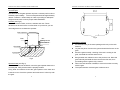
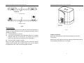
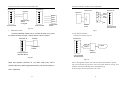
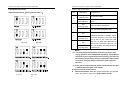
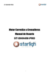
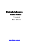
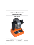
PY800AC/PY1400AC SLIDING GATE OPERATOR
1. Products introduction
Sliding Gate Operator
User's Manual
PY800AC/PY1400AC
Please read the instructions carefully before proceeding.
MCU is supplied to control the gate operator.
Keypad / single button interface.
Have Infrared safety sensor interface.
Soft start and soft stop function and the soft stop width are
adjustable.
Working time is adjustable.
Motor output torque is adjustable.
User can select Auto-close function.
Manual key release designed for emergency purposes.
2. Important safety information
Carefully read and follow all safety precautions and warning before
attempting to install and use this automatic gate operator.
z The gate operator should be installed by a qualified technician;
otherwise, serious personal injury or property damage may
occur.
z
When opening or closing the gate, do not attempt to walk or
drive through the gate.
z
If enable the auto-close function, must use the infrared sensor.
z
Children should not be allowed to play near or operate automatic
gates.
z
The automatic gate operator must be grounded.
z
Install the gate operator on the inside of the property; DO NOT
install it on the outside of the property where the public has
access to it.
z
Be careful when in close proximity to moving parts where hands
or fingers could be pinched.
z
Do not allow control devices to be placed so that a person can
1
PY800AC/PY1400AC SLIDING GATE OPERATOR
PY800AC/PY1400AC SLIDING GATE OPERATOR
access them by reaching through the gate.
z
In the event of power failure, an emergency release key allows
you to operate the gate manually.
z
The operator should be switched off before repairing it or
opening its cover.
z
Please erase and reprogram the transmitter code after installing
the operator.
The PY800AC/PY1400AC will handle gate weighting up to
800kg/1400 kg and up to 14m/20m if the proper installation
procedures have been followed.
The PY800AC/PY1400AC gate operator operates by forcing a drive
rack by a drive gear. The entire configuration is shown in the
diagram below. The gate operator must be installed on the inside of
the gate.
Switch
Make sure the Power supply (AC220V or AC110V) of the gate
operator is suitable for the power supply in your area.
Wall
3. Main technical parameters
Type
Power supply
Motor speed
Sliding gate
PY800AC
PY800ACU PY1400AC
PY1400ACU
220V, 50Hz 110V, 60Hz 220V, 50Hz
110V, 60Hz
52rpm
62rpm
52rpm
62rpm
Input power
Rated output power of
360W
500W
Remote control
30m
30m
operating distance
(Frequency: 433.92mHz)
(Frequency:433.92mHz)
Remote control mode
Single button
Single button
Output shaft height
58.5mm
58.5mm
Max. gate weight
800Kg
1400Kg
Fig.1
Output torque
22N·m
32N·m
Noise
≤60dB
≤60dB
Duty cycle
S2, 15 minutes
S2, 15 minutes
extra remote control
20
20
-20°C~+50°C
-20°C~+50°C
Gate preparation
Be sure the gate is properly installed and slides smoothly before
installing the PY800AC/PY1400AC sliding gate operator. The gate
must be plumb, level, and move freely.
Conduit
In order to protect the cable, use PVC conduit for low voltage power
cable and control wires. Conduit must be preset into the concrete
when it is poured. Wires within the conduit shall be located or
protected so that no damage can result from contact with any rough
motor
Environmental
temperature
Gate Move speed
12m/min
14m/min
4. Mechanical Installation
2
12m/min
Rack
14m/min
Gate operator
3
PY800AC/PY1400AC SLIDING GATE OPERATOR
or sharp part.
Concrete pad
The base unit of the gate operator requires a concrete pad in order to
maintain proper stability. The concrete pad should be approximately
450mm x 300mm x 200mm deep in order to providing for adequate
weight and structure to insure proper stable installation.
Anchors (see Fig.2)
You can use anchor bolts, anchors, washers and nuts. These
anchors must be set into the concrete when it is poured or you can
use wedge anchors to fasten the operator.
230
114
PY800AC/PY1400AC SLIDING GATE OPERATOR
Gate operator
Nut
Gear
Fig.3
Spring washer
Plain washer
Nut
Groundsill
Input power
Fig.2
Operator base (see Fig.3)
After the concrete has hardened, mount the gate operator base to the
concrete pad. Verify that the base is properly leveled.
Using bolts and washers mount the gate operator to the base and
insert the cover. Check the operator and make sure it is lined up with
the gate.
4
Installation of Rack
z Fix the three nuts (in the same package with rack) on the rack
element.
z Lay the first piece of rack on the gear and weld the first nut on the
gate.
z Move the gate manually, checking if the rack is resting on the
gear, and weld the second and third nut.
z Bring another rack element near to the previous one. Move the
gate manually and weld the three nuts as the first rack, thus
proceeding until the gate is fully covered.
z When the rack has been installed, to ensure it meshes correctly
with the gear.
z The space between rack and gear is about 0.5mm.
5
PY800AC/PY1400AC SLIDING GATE OPERATOR
PY800AC/PY1400AC SLIDING GATE OPERATOR
z
gate.
Release the gear with the key and push the sliding gate manually
to pre-determine the position, fix the block to the rack and lock
the gear by push up the release bar. Moving the gate electrically,
adjust the block to the proper position until the position of the
opening and closing meet the requirement.
Sliding gate
Fig.4
5. Adjustment
Spring limit switch
z To ensure safety, it is recommended to install limit switches at
both ends of the gate to prevent the gate from sliding out of the
rails. The rails must be installed horizontally.
z Install the limit block as shown in Fig.5 and Fig.6. The spring limit
switch and blocks are used to control the position of the gate.
z Release the gear with the key and push the sliding gate manually
to pre-determine the position, fix the block to the rack and lock
the gear by push up the release bar. Moving the gate electrically,
adjust the block to the proper position until the position of the
opening and closing meet the requirement.
Magnetic limit switch
z To ensure safety, it is recommended to install limit switches at
both ends of the gate to prevent the gate from sliding out of the
rails. The rails must be installed horizontally.
z Install the limit block as shown in Fig.4 and Fig.5. The magnetic
of limit switch and blocks are used to control the position of the
6
Spring of limit switch
limit block
Rack
Gear
Spring limit
Sliding gate
Magnetic
Limit block
Rack
Gear
Magnetic limit
Fig.5
7
PY800AC/PY1400AC SLIDING GATE OPERATOR
PY800AC/PY1400AC SLIDING GATE OPERATOR
M6X10
Spring limit
Magnetic limit
Pull 90°
Fig.6
Manual operation
In case of power failure use key unlock the lock and pull down the
release bar about 90 degree to open or close gate manually, use the
release key as follow:
z Fit the supplied key in the lock.
z Turn the key and pull down the release bar about 90°to release
the gear. (Note: Do not exceed 90°, be careful not to use too
much force, otherwise the release bar will be damaged.)
z Open and close the gate manually.
Note: If the gate bumps the mounting post and cannot be electric
opened, move the gate a few inches by hand, thus you can release
the gate with the key, open and close the gate manually.
8
Fig.7
6. Wire Connecting
Make sure that the power is OFF before making any electrical
connections.
Remove the cover, perform the wiring (See Fig.8 and wiring notes for
control board) and replace the cover again.
9
PY800AC/PY1400AC SLIDING GATE OPERATOR
VR1
VR3
VR2
PY800AC/PY1400AC SLIDING GATE OPERATOR
VR4
Learn button
ON
OFF
U1
7 8 9 10 11 12 13
POWER
S1
12
9 10
LEARN
U2
Open limit Limit
COM
swtich
Close limit
Loop detector
GND/COM
Infared sensor
+12VDC
5 6
U3
MOT
CAP
C20
J6
Capacitor
MOT1
C19
J4
F1
MOT
COM
POWER
Form two-terminal to the emitter
12--24V AC/ DC
power supply
9
8
JUMP
NC
COM
NO
OUT
7
Control board
NC OR NO
TX Emitter connecting
RX Receiver connecting
Q3
Fig.9 infrared Schematic diagram
PE PE N L
Protect Earth
LAMP
N
L
Caution light
From four-terminal
to the receiver
Terminal J5
Pedestrian switch
O/S/C switch
COM
Extral button
switch
J2
MOT2
OC1
1 2 3
OC2
F3
MOTOR
1 2 3 4 5 6
J5
7
RL2
RL1
C22
SPEED GND VCC
HALL
SW1
X1
J1
SL600ACU: AC110V
Output power supply: 12VDC(7 of J5), COM (9 of J5), I.R. (8 of
J5 is N.C Infrared)
If the infrared beam is interrupted during closing, the gate will reverse
and open immediately. The product is not factory equipped with an
infrared device; the infrared output signal must be N.C.
c.
VDR1
F2
J3
T2
Fig.8
Wiring notes of control board
a. Power Input (terminal J3): PE (Earth),L (Live),N (Neutral).
SL600AC: AC220V
SL600ACU:AC110V
b. Caution light: connect caution light wire to L and N of
LAMP(terminal J4)
SL600AC: AC220V
10
d. Three-button switch / single-button switch (keypad): The
SL600AC is equipped with interfaces for three-button switch and
single-button switch (keypad).
To install the keypad attach one lead of your keypad to ‘5’ of
terminal J2 and the other to the ‘4(COM)’. The keypad will
function in single channel mode.
For three-button switch installation, use the terminals for
multi-channel mode. Connect open wire of external button switch
to ‘1 (OPEN)’ of terminal J2, connect close wire of switch to ‘2
(CLOSE)’, connect stop wire of switch to ‘3(STOP)’, connect
common wire of switch to ‘4(COM)’.
11
PY800AC/PY1400AC SLIDING GATE OPERATOR
terminal J2
6
Capacitor
5
5
4
4
Com
3
3
Stop
Open
Close
2
2
Single-button
switch
or keypad
1
1
Control board
Control board
terminal J4
Terminal J6
6
U
Keypad
V W
Motor
terminal J2
PY800AC/PY1400AC SLIDING GATE OPERATOR
Mot1
Mot2
Mot
COM
PE
Three-button
switch
Control
board
Control board
terminal block
Fig.10A
e.
Pedestrian switch
Connect pedestrian switch wire to 4 and 6 terminal of J2. press
the switch the door will open 1 meter when the door is closed.
Switch
terminal J2
6
Fig.11
f. Loop detector interface
Connect wire see the Fig.11A
terminal J2
12
5
11
4
10
3
Pedestrian
switch
2
1
9
Fig.10B
Motor and capacitor (Terminal J2, J4): MOT COM (com), MOT1
(Positive direction), MOT2 (Opposite direction), PE (Protect Earth), C
and C (capacitor)
12
LOOP
8
7
Control board
terminal block
detector
output
Loop
detector
Control board
terminal block
Fig.11A
The car through the loop the door will close itself when the door opened.
The car arrived the loop the door will reverse when the door closing, and
the door will auto closed after the car through the loop.
If the car stops on the loop the door can’t close.
13
PY800AC/PY1400AC SLIDING GATE OPERATOR
PY800AC/PY1400AC SLIDING GATE OPERATOR
7. Tuning and operation
Remote Pedestrian button: After you learn the button 4, you
press the remote button 4 the door will open 1 meter when the door
is closed.
z You can program/learn button 1, button 2, button 3 and button 4
individually. You also can program/learn two buttons or three
buttons together, but you need repeat the program/learn process
if you want to use more than one button.
a. Adjust the Adjustable resistance (see Fig.8)
VR1: Sensitivity adjustment of meet obstacle.
Clockwise rotation to reduce sensitivity of obstacle, counter-clockwise
rotation increase sensitivity of obstacle.
Button 1
Button 2
VR2: For brake force adjustment in limit position.
Button 3
Clockwise rotation to increase, counter-clockwise rotation to reduce.
Button 4
Rotate to minimum to cancel brake function in place.
VR3: For slow stop width adjustment.
Clockwise rotation to increase, counter-clockwise rotation to reduce.
Fig.12 Remote transmitter
z
VR4: For motor output force adjustment to keep safe usage.
Clockwise rotation to increase, counter-clockwise rotation to reduce.
Warning:
Motor force can not be set too large, just drive the door is ok.
Remote control
z The remote control works in a single channel mode. It has four
buttons. See Fig.12 Remote transmitter. The function of button 1,
button 2、button3 are the same and button 4 is pedestrian mode.
With each press of the remote control button (1, 2 and 3) which
has been programmed, the gate will close, stop, open or stop
cycle.
14
z
z
Adding extra remote controls (Learn): Remove the cover, press
and hold the learn button ‘S1’ (Fig.8) more than 2 seconds, then
the ‘LED of LEARN’ (Fig.8) will be on, then press the remote
control button which you want to use, the ‘LED’ will turn on about
2 seconds and then turn off again. The learning process is
finished.
Up to 25 remote controls may be used.
Erase remote controls: To erase all existing remote controls,
press and hold learn button ‘S1’, the LED of ‘LEARN’ will turns
on, release the button until the LED turns off. This indicates
that all the remote controls have been erased completely.
Verify open direction: If the gate does not move in the desired
direction, then you will need to reverse the motor operating
direction, open the black plastic cover, you can do this by
exchanging wires ‘MOT1’ and ‘MOT2’, ‘Open limit(13 of J5)’ and
‘Close limit(11 of J5)’.
15
PY800AC/PY1400AC SLIDING GATE OPERATOR
PY800AC/PY1400AC SLIDING GATE OPERATOR
8. Programming Process
Table 1: DIP switch adjust
Adjust the DIP switch(see Fig13B and table 1)
DIP
1
1
2
3
4
1
2
3
4
2
DIP-switch
Function SET
ON
(see Fig.13A)
No soft start mode
OFF
(see Fig.13A)
Soft start mode(need to power on
reset).
ON
(see Fig.13B)
N.C. limit switch(spring limit)
OFF
ON
1
2
3
1
4
Fig. 13A
2
3
3
4
ON
Fig.13B
4
1
2
3
4
1
2
3
4
1
2
3
4
1
2
3
4
Fig. 13C
Fig. 13D
16
OFF
(see Fig.13C)
OFF
(see Fig.13D)
N.O. limit switch(magnetic limit)
When the 3 and 4 all OFF, the
Auto-close function is disable. When
the 3 OFF and the 4 is ON, auto-close
time is near 12 Sec. when the 3 ON
and the 4 is OFF auto-close time is
near 24 sec. when the 3 and the 4 is
all in ON position, the auto-close time
is near 36 sec.
NOTE:
(1) You must follow the operating instruction as above, any
wrong operation is not allowed during setting. If your device
responds to your requested function correctly, you have set
the function successfully, otherwise repeat the above setup
instruction until your device responds to your expected
function.
(2) If the gate can not be moved, please check whether the gate
is obstructed or the gate is too weight.
Activities Covered in this section
z Remote transmitter: With each press of the button, the gate will
close, stop, open or stop cycle. (Single-button mode)
17
PY800AC/PY1400AC SLIDING GATE OPERATOR
z
z
z
z
z
z
z
Three-button mode external button switch (not supply):
press ‘OPEN’ button, the gate opens. Press ‘STOP’ button, the
gate stops. Press ‘CLOSE’ button, the gate closes.
Single-button mode external button switch / keypad (not
supply): With each press of the button, the gate will close, stop,
open or stop cycle.
Auto-close function: This feature can be selected to make the
gate stay open for some seconds before it automatically closes.
The auto-close time can be adjusted to between 12, 24 and 36
seconds.
Safe guard (Infrared photocell): If infrared beam is interrupted
during closing, the gate will reverse and go open immediately.
This feature will not function if the gate is in fully opened and
closed positions or during opening.
Open priority: The gate will return to open if press ‘OPEN’
button of external button switch during closing.
Limit switch: The switch is used to accurately stop the gate in
the opened and closed positions.
If the gate stops at opened position when the limit switch is
reached, the gate will not move if you press ‘OPEN’ button.
If the gate stops at closed position when the limit switch is
reached, the gate will not move if you press ‘CLOSE’ button.
The device is installed with a thermal protector, the thermal
protector will switch off the motor automatically in case of the
temperature is higher than 120°C and switch on the motor
automatically when the temperature is lower than 85°C±5 °C.
9. LED indicate
a) LED of Power indicated the input power.
b) LED of LEARN indicated the transmitter learn status.
c) LED 1 indicate the ‘CLOSE’ external button, if the button is
18
PY800AC/PY1400AC SLIDING GATE OPERATOR
pressed the LED will light.
d) LED 2 indicate the ‘OPEN’ external button, if the button is
pressed the LED will light.
e) LED 3 indicate the ‘STOP’ external button, if the button is
pressed the LED will light.
f) LED 5 indicate the ‘O/S/C’ external button, if the button is
pressed the LED will light.
g) LED 6 indicate the ‘pedestrian switch’ external button, if the
button is pressed the LED will light.
h) LED 7 indicate the ‘infrared sensor’ status, if the output is
connected the LED will light.
i) LED 9 indicate the ‘Loop detector’ status, if the output is
connected the LED will light.
j) LED 10 indicate the ‘Close limit switch’ status, if the switch is
connected the LED will light.
k) LED 12 indicate the ‘Open limit switch’ status, if the switch is
connected the LED will light.
All these LED position see the Fig.8
10. Maintenance
z Check the door once a month. The door should be carefully
checked for balance. The door must be in good working order.
z We suggest for safety reasons, photocells be used on all gates.
z Disconnect from mains supply before replacing bulb.
z Be sure to read the entire manual before attempting to perform
any installation or service to the door operator.
z Our company reserves the right to change the design and
specification without prior notification.
19
PY800AC/PY1400AC SLIDING GATE OPERATOR
PY800AC/PY1400AC SLIDING GATE OPERATOR
11. Troubleshooting
12. Packing list
After receiving the gate operator, you should make an
unpack-inspection, in which you should check whether the product
was damaged. If you have any problem please contact our dealer.
You should find the following items in our standard packing:
Trouble
Possible causes
The door fails to
open and close.
LED
display
does not light.
1. Power is OFF
2. Fuse burn
The door can
open fails to
close.
1. Infrared beam is
obstructed.
2.
Infrared
sensor
function is enabling, but
the sensor has not been
installed.
Solutions
1. Make sure that
power is ON.
2. Replace fuse.
1.
Remove
obstructions.
2. Make sure the
infrared
sensor
function is disabling.
Remote
transmitter does
not work.
1. Battery level may be
low
2. Transmitter code is
lost
1.
Replace
battery inside
transmitter.
2. Reprogram
transmitter.
The transmitter
operating
distance is too
short.
Battery level may be
low.
Replace battery.
20
the
the
No.
1
Item
PY800AC/PY1400AC sliding
gate operator
Quantity
1
2
Transmitter
2
3
Release key
2
4
User’s manual
1
the
21