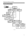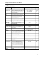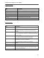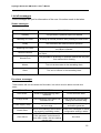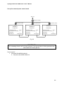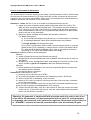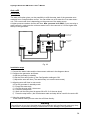
1
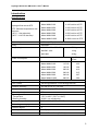
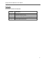
Hydrogen generator model NM Series II User’s manual Rev. E March 2008 This manual provides operation and maintenance instructions for model NMH2-100, NMH2160, NMH2-250, NMH2-300, NMH2-500, NMH2-600 and NMH2-1000 hydrogen generators. MATHESON TRI-GAS Keystone Drive Montgomeryville, PA 18936 Phone: 215-641-2700 Fax: 215-641-2714 Email: [email protected] Hydrogen Generator NM Series 2 User’s Manual Index INDEX.................................................................................................................................................................... 1 INTRODUCTION................................................................................................................................................. 2 SPECIFICATIONS .................................................................................................................................................. 2 NOTES ON FCC COMPLIANCE .............................................................................................................................. 3 CORRECT USE ...................................................................................................................................................... 3 PACKING LIST ...................................................................................................................................................... 4 DESCRIPTION ..................................................................................................................................................... 5 INSTALLATION .................................................................................................................................................. 6 RECEIVING THE GENERATOR ............................................................................................................................... 6 PLACING THE GENERATOR ................................................................................................................................... 6 GAS CONNECTIONS .............................................................................................................................................. 6 ELECTRICAL CONNECTIONS ................................................................................................................................. 7 INITIAL START-UP ............................................................................................................................................ 8 FILLING THE WATER TANK ................................................................................................................................... 8 INSTALLING THE DEIONIZER BAG ......................................................................................................................... 9 OPERATION ...................................................................................................................................................... 10 LAYOUT OF THE START UP DISPLAY .................................................................................................................. 11 MENU TREECONFIGURE PARAMETERS.............................................................................................................. 13 CONFIGURE PARAMETERS ................................................................................................................................. 14 DIAGNOSTIC DISPLAY ........................................................................................................................................ 15 SPECIAL FUNCTIONS .......................................................................................................................................... 15 LIST OF MESSAGES ........................................................................................................................................ 16 STATUS MESSAGES ............................................................................................................................................ 16 PRE-ALARM MESSAGES..................................................................................................................................... 16 ALARM MESSAGES............................................................................................................................................ 17 MAINTENANCE ................................................................................................................................................ 18 ROUTINE MAINTENANCE ................................................................................................................................... 18 CLEANING ......................................................................................................................................................... 18 WATER REFILLING ............................................................................................................................................. 18 DEIONIZER BAG REPLACEMENT ......................................................................................................................... 18 LONG TIME STORAGE ........................................................................................................................................ 18 OPTIONS............................................................................................................................................................. 19 REMOTE CONTROL ............................................................................................................................................ 19 CASCADING ....................................................................................................................................................... 21 AUTO REFILL ..................................................................................................................................................... 24 RETURNING THE UNIT .................................................................................................................................. 25 SPARE PARTS LIST.......................................................................................................................................... 26 1 Hydrogen Generator NM Series 2 User’s Manual Introduction Specifications Hydrogen flow rate at STP. STP: Standard temperature and pressure: (20°C / 1 bar absolute) (68°F / 14.4 PSI absolute) Model NMH2-100 0-100 cc/min at STP Model NMH2-160 0-160 cc/min at STP Model NMH2-250 0-250 cc/min at STP Model NMH2-300 0-300 cc/min at STP Model NMH2-500 0-500 cc/min at STP Model NMH2-600 0-600 cc/min at STP Model NMH2-1000 0-1000 cc/min at STP Max outlet pressure 10.5 bar (155 psi) Purity 99.9999% Weight (dry) NM 100 - 160 – 250 - 300 17.5 kg NM 500 - 600 19 kg NM 1000 20 Kg Model NMH2-100 090 VA Heat Dissipation BTU/h 184 Model NMH2-160 115 VA 235 Model NMH2-250 160 VA 328 Model NMH2-300 200 VA 410 Model NMH2-500 300 VA 615 Model NMH2-600 340 VA 697 Model NMH2-1000 480 VA 984 Power consumption Input voltage 120 or 240V / 50-60Hz selectable Fuse (5x20) 4A SLB @ 240VAC / 6.3A SLB @120 VAC Pressure accuracy 0.1 bar (± 0.5 %) (1.4 PSI) Microprocessor controlled display Graphic display, 128 x 64 pixels Index of protection Operating conditions: - Temperature - Relative humidity Storage Temperature IP2x Over voltage category II Pollution degree 2 Sound pressure level 46 dB(A) Case dimensions 230 x 355 x 410 mm (WxDxH) 15°C to 40°C ( 59°F to 104°F) 0-80%, non condensing 2°C to 60°C (35°F to 140°F) 2 Hydrogen Generator NM Series 2 User’s Manual Notes on FCC compliance This equipment has been tested and found to comply with the limits for a Class B digital device, pursuant to part 15 of the FCC Rules. These limits are designed to provide reasonable protection against harmful interference in a residential installation. If not installed and used according the “Installation Instructions”, the instrument may cause harmful interference to radio communication equipment or other electronic devices. If there is any indication of interference, just turn the instrument off and see if the problem(s) disappears. If the problem remains, consult with the instrument supplier for corrective action WARNING! Any changes or modifications to this equipment not expressly approved by Matheson TriGas’ will void the Warranty obligation and in no case will Matheson Tri-Gas be liable for incidental or consequential damages, loss of use, loss of production or any loss incurred. Correct use The Hydrogen generator is designed to produce hydrogen for laboratory use. The unit must only be operated for this purpose, according to the specifications and instructions provided in this manual. In particular, the following rules should be observed at all times: Indoor use only Never store the unit in temperatures below 2°C (35°F) This will cause irreversible damage to the electrolysis cell !!! Only use pure water (see “Filling the water tank”) Only operate the unit in a room with sufficient ventilation (see “Placing the unit”). Always depressurize (put in standby) before shutting down the unit. Unplug the unit from the mains power supply before accessing the internal components for replacement. Note: Service should only be done by qualified technicians. 3 Hydrogen Generator NM Series 2 User’s Manual Packing list List of items included in the shipment Quantity Description 1 Hydrogen generator 1 Instruction manual (on CD) 1 Deionizer triangle bag MDI-TBAG 1 Water drain with flexible tubing MHSE-0059-XX 1 Power cable MLCD-0004-XX 4 Hydrogen Generator NM Series 2 User’s Manual Description The hydrogen generator produces pure hydrogen (and oxygen as a by-product) by the electrolysis of water. The key element of the generator is an electrochemical cell assembly which contains a solid polymer electrolyte. No free acids or alkalines are used. De-ionized or pure, distilled water is the only liquid which may come into contact with the cell. As water is consumed it must be refilled from time to time as required. The generated hydrogen gas is accumulated in the hydrogen/water separator and is dried by passing through the automatic dryer. The internal pressure (11.0 Bar / 160PSI) is controlled by the amount of hydrogen generated by the cell. The outlet pressure is controlled by a proportional valve. Safe operation is guaranteed by the following safety features: - Overpressure Valve - Intelligent pressure monitoring - The hydrogen production is automatically stopped, when no hydrogen is needed, or there is a large leak in the output line. H2 Vent H2 GLS low press. H2 GLS high press. H2 Pressure relief Int. Press. Sens. Dryer Water Tank Ext. Press. Sens. H2 Outlet Drain port / Autorefill connector O2 Vent O2 GLS low press. Cell Fig. 1 5 Hydrogen Generator NM Series 2 User’s Manual Installation Receiving the generator All units have been carefully inspected before transport. Visual checks for damage and functional tests should be performed upon receipt. Any damage has to be immediately noted and reported to the shipping agent and supplier. The generator has to be returned according to the shipping instructions provided. Placing the generator The hydrogen generator should be placed on a flat, level, vibration-free, shock-free surface. Do not place the generator over or near a source of heat, as this may cause the device to overheat. The unit should not be in contact with any other objects on any side, and the air inlet must not be blocked. Leave at least 30 cm of free space at the rear for ventilation. Do not operate the generator in a sealed or unventilated room, or in close proximity to open flame or other sources of ignition. The ambient temperature (preferable stable) has to be between 15°C. (59°F) and 40°C (104°F). WARNING! Compared to cylinders, the gas volume of the generator is very small. However precautions for any hydrogen supply should be taken when using the generator. DO NOT use the generator in sealed or unventilated rooms, neither use it in close proximity of open flames or other sources of ignition. Gas connections Pure dry hydrogen at regulated pressure is available at the hydrogen outlet port at the rear of the generator. This port must be connected to 1/8" SS or copper tubing using the appropriate Swagelock fittings. Teflon tubing is not suitable. The pressure at this port is adjusted via the keyboard and shown on the display. The hydrogen relief port at the rear of the unit can be connected to an exhaust hood or other vent system. WARNING! The line from the relief port (over pressure) should never be connected in such a way that back pressure can develop. 6 Hydrogen Generator NM Series 2 User’s Manual IMPORTANT! Remove the plugs from the oxygen vent and hydrogen vent before operating the unit. Keep these plugs for transporting the unit. (For return of the unit to the factory) Fig.2 Electrical connections Check the setting of the voltage selector on the rear of the unit. The set voltage is indicated by the white arrow. To change the voltage, proceed as follows: Using a small screwdriver, remove the voltage selector insert. Replace the voltage selector insert so that the white arrow points to the correct voltage. Use only 240 VAC or 120 VAC setting! Fig. 3 Fig. 4 Fig. 5 7 Hydrogen Generator NM Series 2 User’s Manual Initial start-up Filling the water tank To fill the water, remove the cap under the slider on the water tank (Fig. 6). Carefully fill the tank with distilled or deionized water. The conductivity of fresh water, used in the generator, should not exceed 2S. Note : During operation the conductivity can increase. This is normal, but if the value succeeds 20 uS, it is recommended to replace the deionizer bag. Fill the tank to the maximum level indicator. Close the slider cap. WARNING! Do not fill the water tank higher than the marked max level. CAUTION! It is important to use only deionized or distilled water in the generator. Standard water containing impurities will contaminate and damage the cell, and will void the warranty. Fig. 6 Fig. 7 Note: The blue light produced by LED’s on the Main board make it easier to see the water level in the tank. 8 Hydrogen Generator NM Series 2 User’s Manual Installing the deionizer bag The triangle deionizer bag has been designed for a higher water purifying capacity. It is recommendable to use this bag for new generators, in the first 4 to 6 months of operation. After this time you can use the standard deionizer bag (see “spare parts”). Fig. 8 Triangle deionizer bag Fig. 9 Standard deionizer bag After having filled the tank with water, the triangle deionizer bag (supplied) must be placed in the tank. Inspect the bag thoroughly for holes or tears, indicated by loose deionizer beads on the outer surface. If the bag is damaged in any way, discard and replace it with a new one. Only use original parts (see Spare Parts). Wash the deionizer bag in deionized water before proceeding. Insert the free end of the “T” fastener through one of the holes of the holder, until it is securely fastened (Fig. 10). Insert the bag in the opening of the tank (Fig 11). Fig. 10 Fig. 11 9 Hydrogen Generator NM Series 2 User’s Manual Operation First turn on the main power switch at the rear of the unit. The display will show the software version installed followed by a “self checking” period of 20s. Fig.12 Than the main screen appears Function buttons description LED 2 Function buttons LED 1 Fig. 13 LED 1 (green) This LED has two states : flashing or continuously on 1. Flashing – the generator is powered up – the unit is in Standby mode – the unit is building up internal pressure – the main valve is closed 2. Continuously on - the main valve is “Open” and the unit is in “Normal” operation.(Fig.17) LED 2 (red) This LED flashes in case of an error. See Alarm List to find out more details. 10 Hydrogen Generator NM Series 2 User’s Manual Layout of the Start up display Fig. 13 First row, status information The Status: shows current information on the operating status of the generator. Second row, pressure information “Press Act”: is the actual pressure of the hydrogen outlet. Third row, set pressure “Set” is the adjusted pressure in the pressure set menu. Forth row, hydrogen flow Bar Graph This row displays the current quantity of hydrogen being produced. Each segment represents around 10 % of maximum capacity. This graph also indicates how much hydrogen is being consumed by the connected equipment. Note: during initial build up of the internal and external pressure and to maintain the internal pressure, the displayed flow will temporarily go to maximum and deviate from the actual flow on the gas outlet. Fifth row, water quality Bar graph This graph shows the quality of the water in the reservoir. With more than 7 segments illuminated, water quality is good. If only 3 or less points are illuminated, the conductivity of the water is around 30 uS (pre-alarm level). If only 1 segment or no segments are illuminated, the conductivity of the water is equal to or greater than 40 uS (alarm). The generator will shut down. 11 Hydrogen Generator NM Series 2 User’s Manual Function buttons The functions of these buttons depend on the place in the Menu tree. The actual function is displayed just above each button. Fig.13 Start button Pushing this button will start the hydrogen production. The display will show “Reaching Int. Pressure” Additionally the percentage of internal pressure reached will be displayed.(Fig.14). When the final internal pressure is reached (11 bar /160 PSI), the display will show “Ready”. Fig.15 Fig.14 Fig.15 Open button This function will appear after the generator has been started. When this button is pushed the proportional valve slowly opens, in order to reach the external pressure, as defined in the “Pressure Adjust” Menu. The display shows “Reach Ext. Press (”Fig.16). When the button is pushed before the internal pressure has been reached, it will flash, and the valve will start to open as soon as the internal pressure has been reached. Fig.16 Fig.17 Note : The proportional valve may need up to two minutes to build up the adjusted pressure. Menu button With this buttons the user can enter the Menu tree. 12 Hydrogen Generator NM Series 2 User’s Manual Menu Tree “Configure Parameters” Status: Normal Flow Press act: 6.2 set: 6.2 Bar Flow Water Start Open Menu Pressure adjust Configure Utilities Select Exit Scroll Menu Pressure Adjust Configure 6.2 Bar Exit Autorefill Set autorefill time Select Exit Autorefill Set autorefill time Off Auto Manual Exit Start Scroll Select Exit Auto Manual 3s 3s Stop Scroll Select Exit Select Scroll Exit Set Clock Pressure Rise Pressure drop delay Auto start Beeper Cascading mode N. Gen H2 in cascading ID number Remote start /stop mode Remote relay mode Autorefill Pre alarms in alarm list Pressure units Temp units Volume units Lock keyboard Display contrast Set default values Autorefill Scroll Utilities Alarm list Diagnostics Special functions Set Clock Pressure Rise Pressure drop delay Exit Exit Alarm list Alarm Number: 1 21.01.03 17:00 Low water Diagnostics Special Functions Prod. Tot. : 10000 scm Oper. time : 100 H W. Quality: 2.5 uS Dryer Status System Test Hardware options Exit Scroll Exit Prod. Tot. : 10000 scm Oper. time : 100 H W. Quality : 2.5 uS Int. Press. : 11 Bar Cell Volt. : 3.6 V Cell Curr. : 33 A PS Temp: 40°C Cell Vpeak: 3.8 V PS Temp peak : 45°C Scroll Select Exit System test Hardware options Internal Leak Test External Leak Test Flow Test Enable Heater Test Enable Moisture Alarm Select Valve Bloc Type Select Exit Internal Leak Test External Leak Test Flow Test Heater Test Rinse Flow Test Complete System Test Toggle Valve Scroll Select Exit Enable Heater Test Enable Moisture Alarm Select Valve Bloc Type Release P. in Standby Fig. 18 13 Hydrogen Generator NM Series 2 User’s Manual Configure Parameters Item Description Options / Range Default Set Clock Allows to set the internal Clock - - Pressure rise Sets how fast the pressure has to increase. If the pressure increases at a slower rate, a low output pressure alarm is activated. 0.01 – 4.2 bar/min 0.09 0.2 - 60 psi/min 14 Pressure drop delay Sets a delay in minutes before a low output pressure alarm is triggered 2 - 10 min 2 Auto start Sets whether or not the unit automatically starts production when power is switched on. YES / NO NO Beeper Sets whether or not the audible signal is activated in the event of an alarm. ON / OFF ON Cascading mode Sets the cascading mode. (see cascading for more details) None/ Normal / Ext. P control None N Gen H2 in cascading Sets the number of generators in the 1-10 1 ID number Sets the ID number 1-10 1 Remote start/stop mode Configures the remote start/stop function (For more details see Remote option) Start/stop, Start only, Direct control start/stop Remote relay mode Configures the remote relay contacts. Normally open (NO) NC Autorefill If set to ON, the pre-level water alarm is used to trigger an external pump or valve to refill the water tank ON / OFF OFF Pre alarms in list If set to Yes, the pre alarms are also shown in the alarm log. YES / NO NO Pressure units Sets the desired unit of measure for the pressure bar / psi / kPa bar Temp. units Sets the desired unit of measure for the temperature °C and °F °C Volume units Sets the desired unit of measure for the volume scm (standard cubic meters) scm Cascading chain Normally closed (NC) Lock Keyboard If set to Yes, the keyboard will be locked automatically after the generator is in the main window for more than 20s. To unlock the keyboard, press the unlock button and hold for 5s. Display contrast Adjusts the contrast of the display. Set default Sets all configuration parameters to values default scf (standard cubic feet) YES / NO NO 0 - 10 5 14 Hydrogen Generator NM Series 2 User’s Manual Diagnostic display Item Description Production Tot. Total production of hydrogen Operating time (h) Total number of hours the unit has been in operation Wat. quality (S) Actual water conductivity Int. Press.: Actual internal pressure of the unit Cell voltage (V) Actual cell voltage Cell current (A) Actual cell current PS. temp. Actual temperature of the power supply Cell voltage peak (V) The maximum cell voltage since last power up PS. temp. peak The max. temp. of the power supply since last power up Special functions Item Description Dryer status Shows the temperatures of the drying columns and the position of the cycle System test This offers several test functions see below Important: this function will only work if the generator is in standby Internal leak test The outlet valve is closed, the pressure is set to the max. When the pressure reaches the max., production is stopped and the pressure drop is measured over 2 minutes. The pressure drop should be below 0.7 bars or 10 PSI External leak test Works similar to the leak “ internal leak test” except the outlet valve is open and the test pressure is equal to the set pressure Flow test This function can be used to test the external gas lines This function sets the outlet valve to provide a certain flow Adjustable from 0 to 100% of maximum flow. Heater test Note: It will take approx. 2 minutes to get a stable flow! This test checks if there is a reaction of the heaters when power is applied. Rinse flow test This test checks the amount of gas flow, for the dryer regeneration Complete system test Toggle Valve Combination of all tests above Used to switch the valves manually ( for advanced diagnostics only) Important : after exiting this window, the valves will return to the status prior to entering this test Hardware options not available for user (password protected) 15 Hydrogen Generator NM Series 2 User’s Manual List of messages These messages are just for information of the user. No action needs to be taken. Status messages MESSAGE DESCRIPTION Standby The generator is powered up but not started Reaching int. Press. Building up internal pressure after pressing the start button Ready The Generator has reached internal pressure Reaching ext. Press. The generator is producing H2 and pressure increases until the set value is reached Normal Pressure The generator is producing H2 and has reached the set pressure value Normal Flow The generator is producing H2 and has reached the set pressure value with H2 flowing Master This unit is the master in the cascading chain Slave This unit is a Slave in the cascading chain Pre-alarm messages These Alarms will not shut down the Generator, but action must be taken to avoid shut down. MESSAGE DESCRIPTION ACTION Refill Water Water level approaching alarm threshold Fill the tank with water Change Water The conductivity of the water has exceeded 30 uS Drain and then refill the tank; change the deionizer bag Power supply Temp The temperature inside the genera- Check for proper ventilation space tor is too high around the generator Check Slave One or more slave(s) are not work- Check error messages of slaves, ing properly (cascading mode) configuration settings, cables Clock failure The clock is not set. (If the generator is shut down for more than a week, the time setting may be lost) Set clock 16 Hydrogen Generator NM Series 2 User’s Manual Alarm messages These alarms will shut down the generator. MESSAGE DESCRIPTION ACTION Low internal pressure The internal pressure cannot be reached Notify service agent Low out pressure The set pressure can not be reached Check for leaks in the external tubing, or H2 consumption is higher than the generator capacity Low Water The water level in the reservoir is too low Refill the reservoir Bad Water The conductivity of the water has exceeded 40 uS High Cell Voltage The cell voltage is too high Drain and then refill the tank; change the deionizer bag bag Notify service agent Over current The current for the cell is too high Notify service agent The output pressure is too high Check if any gas is fed back into the generator from an external source Check int. press. in the Diagnostics, if higher than 11.2 bar (163 PSI) notify service agent Over pressure Over PS Temp Dryer Failure Check auto refill The temperature of the generator is Check for proper ventilation space too high around the generator Communication failure between Notify service agent dryer module and main board The water is not refilled in time with Check water supply, tubing, filter auto refill and configuration settings Heater Failure 1 Heater 1 does not work properly Notify service agent Heater Failure 2 Heater 2 does not work properly Notify service agent 17 Hydrogen Generator NM Series 2 User’s Manual Maintenance With proper care and maintenance, your hydrogen generator should provide you with years of trouble-free operation. There are no adjustments to be made to the generator. The only routine service operations are those described below. Nonetheless, it is recommended to have the generator inspected approximately every 2 years or more frequently if the generator is installed in a rather dusty environment. Contact your service agent. Routine maintenance The following section describes the maintenance operations required for the correct operation of the hydrogen generator. Cleaning The internal components of the hydrogen generator do not need to be cleaned and should not be accessed by the user for cleaning. To clean the outside of the unit, only use a damp cloth (no detergents, acids or aggressive or abrasive substances. Water refilling The tank must be refilled when the water level approaches the lower level, and the Refill Water pre-alarm message appears. Deionizer bag replacement Rinse the water tank and replace the deionizer bag approximately every six months, and whenever the “Change Water” message appears. See installing the deionizer bag. Long time Storage If the Generator is not used, or stored for more than 2 weeks, it is very important to fill the water tank at least to half full. This will avoid the dry-out of the cell. Don’t leave new generators in the packing for more than a week, this can damage the cell. WARNING! Dried out cells will cause irreversible damage, which is not covered by warranty! 18 Hydrogen Generator NM Series 2 User’s Manual Options Remote control The hydrogen generators can be fitted with an I/O board. There are two possibilities with this board: 1) Analog remote control with potentially free relay contacts to check the status of the machine, and an input to start/stop the production of hydrogen. The contacts can be configured via the Configuration Menu as normally-open or normally-closed (see the Configuration section). The maximum voltage and current ratings for the relay contacts are 1A / 48V (outputs). The input signal can be configured in 3 different modes: a) start/stop: In this mode a pulse (positive edge) starts the generator and opens the main valve after the internal pressure is reached. (during building up the internal pressure, the “open” button is flashing). The next pulse will put the generator in Standby b) start only: In this mode the generator can be started by a pulse (positive edge) or continuous signal. The main valve will be opened when the internal pressure is reached. (During build-up of the internal pressure the “open” button is flashing). The Stop action is via the key board. c) direct control:In this mode the generator is producing hydrogen and the valve is open as long as the input signal is high. When the signal goes low the generator goes in Standby. Remote connector pin configuration Pin Description 1+2 Start 12-30 VDC (pin.1 = 0V, pin. 2 = positive) 3+4 Standby 5+6 Reaching external pressure 7+8 Refill water 09+10 Low water level 11+12 Bad water 13+14 Change water 19 Hydrogen Generator NM Series 2 User’s Manual Start /Stop H2 generator Control box I/O board Status Information Remote control box sample (NOT for sale) Fig. 19 Parts required: 1. I/O board P/N MCBD-0199-XX 2) Digital Remote control via RS-232 with special software available from Matheson Tri-Gas. In this configuration the Generator can be fully controlled via PC (Fig.20) Fig. 20 20 Hydrogen Generator NM Series 2 User’s Manual Parts included: 1. cable RS 232 2. Software for Windows (compatible with Windows 2000/XP) P/N MCBD-0194-XX Cascading The RS-485 interface allows up to 10 generators to be operated in parallel mode. There are Two modes available. Software compatibility! Before generators can be cascaded, it must be clarified that their software versions are compatible and can work together. Normal mode: in this mode the gas outlet of each generator will be connected directly into a gas line and the pressure is controlled by the generators. This works fine with two generators. External Pressure control: In this mode the generators are connected with an external non return valve to the gas line. The pressure must be controlled with an external pressure regulator. The outlet pressure is fixed to 10.3 bars. This mode allows up to 10 generators in a cascading group. How does cascading work The communication of the generators is done via the RS-485 Interface. For a correct communication each generator needs a unique ID number. Each generator must know how many generators are connected in the cascading group. As soon as the generators are powered up, one generator becomes the master, and controls the others (slaves). If there is a problem with the master, one of the slave generators will become the master. Every generator can be forced to be the master, by entering into the menu you will see the function “force to master”. Than just select this function and acknowledge. When a generator is the master, you can see the letter “M” in the menu button, while the slaves show the letter “S”. Set up for Normal mode Gas Line H2 Out H2 Out Generator 1 Generator 2 Configuration: Configuration: Cascading mode : Normal N. Gen H2 in Cascading : 2 ID Number :1 Cascading mode : Normal N. Gen H2 in Cascading : 2 ID Number :2 RS-485 port RS-485 port Fig.21 21 Hydrogen Generator NM Series 2 User’s Manual Set up for external press control mode Gas Line Pressure controler Non Return Valve Non Return Valve Non Return Valve H2 Out H2 Out H2 Out Generator 1 Generator 2 Generator 3 Configuration: Configuration: Configuration: Cascading mode : Ext P N. Gen H2 in Cascading : 3 ID Number :1 RS-485 port RS-485 port Cascading mode : Ext P N. Gen H2 in Cascading : 3 ID Number :2 RS-485 port RS-485 port Cascading mode : Ext P N. Gen H2 in Cascading : 3 ID Number :3 RS-485 port RS-485 port Fig. 22 IMPORTANT! The cascading function will only work properly if the gas outlets on all the generators are connected to the same gas line. Parts required: 1. I/O board P/N MCBD-0199-XX 2. Cascade cable MCBL-0082-XX 22 Hydrogen Generator NM Series 2 User’s Manual Service of Cascaded H2 Generators We assume that the units are working in the mode: “external pressure control” which means all units have an output pressure of 10.3 bar(148.3 psi) and are connected to the common supply line via a non return valve (NRV), which in turn is connected to an external pressure regulator which sets the pressure for the consumers. Situation I: a slave with ID= 3 out of 10 needs to be disconnected for service: 1) switch the power off with the power switch at the back side of the unit(*). The NRV will close and avoid that H2 leaks back. The pressure may drop a little [e.g 10.3 (148.3 psi)>>>9.5 bar (136.8 psi)] for a moment until the other generators have compensated for the lost unit. It is assumed that total flow can still be delivered by the rest of the generators. 2) Result: an Alarm message at the Master but operation continues. For short interruptions: a) If one accepts this beeper tone all the time, no further action is necessary. b) If the beeper disturbs, switch off the Alarm/beeper at the Master. For longer periods of maintenance /repair: a) Go in the “Configuration“ table of each unit and change the Nr of units cascaded (N.Gen H2 in cascading) + change the ID in those units which had an ID > than the ID of the disconnected unit in order to get again a continuous numbering of ID’s. Move the RS485 cables accordingly. Situation II: a Master needs to be disconnected. Option A : 1) switch off power at the rear just like with the slave(*). 2) Another Slave will automatically take over as Master. Which one can be seen on the Display. 3) As above, go in the “Configuration table “and change the Total Nr of units, ID Nr where needed to get ID’s in sequence. Move the cables accordingly. Option B: 1) before switching off the Master, one can force a particular Slave to become the new Master (force to Master) 2) proceed as above in situation I. Situation III: reconnection of a unit. 1) power up the unit and let it go to STBY 2) go in the Configuration table and set the Cascading mode to “Ext.Press” 3) set the “N Gen H2 in cascading” to the new total 4) select an ID = last in the series. In this way the other units need only a modification of the total number. Note: of course it is possible to give the unit the old ID it had when deleted from the group but than it requires more adaptations of ID numbers 5) connect the RS 485 cable. If the ID = last number N, than just connect the cable to the unit N-1. If the old ID= Nx is given, than the cable needs to be inserted between unit with ID=Nx-1 and Nx+1. *Warning: If a generator is switched off with the power switch in order to take it out of the chain, the automatic cell depressurisation will not work! To avoid premature cell damage, the unit needs to be switched on again as Stand-alone unit and then set in “STANDBY” mode for at least 30 seconds before it can be switched off again. 23 Hydrogen Generator NM Series 2 User’s Manual Auto refill Description The auto refill option gives you the possibility to refill the water tank of the generator automatically from a external water source. You can either use a DI water line or a water reservoir. The correct refill time is depending on the pressure of the water source. A higher pressure needs a shorter refill time. Max. pressure is 60 PSIG. If you are using a water reservoir, make sure the minimum water level in the reservoir is 2-3 feet higher than the top of the generator. Generator Filter From DI water line or water reservoir 100 to 240 VAC 50/60 Hz 24 VDC Remote Output Input Drain port Fig. 23 Installation steps 1. Connect the water tubes and the interconnect cable as in the diagram above. 2. Configure the generator as follows: a) Set the generator to standby b) Set the auto refill function in the Configuration settings to ON c) Adjust the auto refill time (The easiest way is to use the auto mode) 3. Adjusting auto refill time in auto mode: a) Put the generator in standby mode b) Empty the water tank c) Go into the auto refill / Auto menu d) Press the start button e) Wait until the filling level is approx 30 to 50 % of the max level) f) Press the stop button. (the time between start and stop will be used for the auto refill. 4. Using the manual mode. In the manual mode you can enter the refill time directly. Warning If the refill time is too high, the water tank of the generator will overflow and water may drop on electronic components resulting in malfunction or even damage of the generator. 24 Hydrogen Generator NM Series 2 User’s Manual Returning the unit In the event of any faults or damage, first notify the agent or distributor who supplied the unit. Please also provide full details of the problem, including the model and serial number. Instructions will then be provided for the service or the return of the unit. If the warranty has expired, or the fault is due to misuse of the unit, all repair and shipping costs are to be paid by the customer, except as otherwise expressly agreed upon. Transport! If the unit has to be transported or returned to the factory for repair, make sure that the water tank is completely empty, and place the plugs (supplied with the unit) on the oxygen/ H2 vent at the rear of the unit. Close the water tank with the cap. Use suitable packaging, if possible the original shipping box. The unit has to be transported in an upright position and this warning label should be clearly visible on the outside of the packaging. Attention: In winter the shipping box has to be additionally marked with a special label informing the shipping agent that the generator may not be exposed to temperatures below 2 ° C (35 °F) at any time. 25 Hydrogen Generator NM Series 2 User’s Manual Spare parts list The table below provides a list and description of the spare parts of the hydrogen generator. p/n DESCRIPTION MDI-BAG Deionizer bag MDI-TBAG Deionizer triangle bag MHSE-0059-XX Water drain with flexible tubing MLCD-0004-XX Power cable MHOL-0129-XX Holder for deionizer bag Please note: The manufacturer reserves the right to change or modify the listed products/parts without prior notice. 26