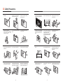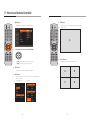
1
Ultra High Definition LED ORION CO.,LTD. www.oriondisplay.net Address: 257-6, Gongdan-dong, Gumi-si, Gyeongsangbuk-do, Korea Tel : +82-2-6678-8533, Fax: +82-2-6678-8599 User’s Manual • 2013.05.31 Thank you for purchasing this product. Please read this manual thoroughly prior to install the product for your safety. Features ▶Enjoy a wide flat screen with high brightness and high quality. ▶Easy to install and move due to its thin design ▶Enjoy your favorite programs with various split-screen features simultaneously presenting several programs. Notice to users It is a device designed for business purpose with a safety certificate for electromagnetic interference, which user should be mindful of. Thank you for purchasing this product. This manual describes how to use the product and notes in use. Please read the manual carefully before using it. After reading this manual, please retain for future reference. If you have any questions or a problem occurs, please contact either the company you purchased this product from or an authorized service center. ※Displaying static picture for an extended period of time may cause an burn-in effect. ※Burn-in effect and the faults in brightness and picture elements caused by fixed images are not subject to the warranty coverage. Warning Class A digital device If you fail to comply with the regulations for safety and proper use, fire or injury may be caused. " Important Safety Instructions" 1) Read these instructions. 2) Keep these instructions. 3) Heed all warnings. 4) Follow all instructions. 5) Do not use this apparatus near water. 6) Clean only with dry cloth. 7) Do not block any ventilation openings. Install in accordance with the manufacturer’s instructions. Warning 8) Do not install near any heat sources such as radiators, heat registers, stoves, or other apparatus (including amplifiers) that produce heat. To prevent electric shock, Do not remove cover. No user serviceable part inside Refer servicing to qualified service personnel. 9) Do not defeat the safety purpose of the polarized or grounding-type plug. A polarized plug has two blades with one wider than the other. A grounding type plug has two blades and a third grounding prong. The wide blade or the third prong are provided for your safety. If the provided plug does not fit into your outlet, consult an electrician for replacement of the obsolete outlet. Supplied Accessories 10) Protect the power cord from being walked on or pinched particularly at plugs, convenience receptacles, and the point where they exit from the apparatus. 11) Only use attachments/accessories specified by the manufacturer. User's Manual HDIM Cable 4EA Power Cable RS-232C Cable Remote Control Battery (AAA X2) IR Receiver 12) Use only with the cart, stand, tripod, bracket, or table specified by the manufacturer, or sold with the apparatus. When a cart is used, use caution when moving the cart/apparatus combination to avoid injury from tip-over. 13) Unplug this apparatus during lightning storms or when unused for long periods of time. 14) Refer all servicing to qualified service personnel. Servicing is required when the apparatus has been damaged in any way, such as power-supply cord or plug is damaged, liquid has been spilled or objects have fallen into the apparatus, the apparatus has been exposed to rain or moisture, does not operate normally, or has been dropped. The symbol in figure 21 shall be shown adjacent to the text of item 12 above. Options Cable tie Cable tie base Monitor clip Form strip -1- Content 01. Cautions.......................................................................................................................................................................................................................4 CAUTION RISK OF ELECTRIC SHOCK DO NOT OPEN CAUTION : TO REDUCE THE RISK OF ELECTRIC SHOCK, DO NOT REMOVE COVER (OR BACK). NO USER-SERVICEABLE PARTS INSIDE. REFER SERVICING TO QUALIFIED SERVICE PERSONNEL. This symbol is intended to alert the user to the presence of uninsulated "dangerous voltage" within the product's enclosure that may be of sufficient magnitude to constitute a risk of electric shock to persons. This symbol is intended to alert the user to the presence of important operating and maintenance(servicing) instructions in the literature accompanying the appliance. NOTICE 1. To disconnect the apparatus from the mains, the plug must be pulled out from the mains socket, therefore the mains plug shall be readily operable 2. WARNING - To Reduce The Risk Of Fire Or Electric Shock, Do Not Expose This Appliance To Rain Or Moisture. 3. Apparatus shall not be exposed to dripping or splashing and no objects filled with liquids, such as vases, shall be placed on the apparatus. 4. Use only a properly grounded plug and receptacle 5. "Warning" CAUTION – These servicing instructions are for use by qualified service personnel only. To reduce the risk of electric shock, do not perform any servicing other than that contained in the operating instructions unless you are qualified to do so. 6. "Warning" CAUTION – These servicing instructions are for use by qualified service personnel only. To reduce the risk of electric shock, do not perform any servicing other than that contained in the operating instructions unless you are qualified to do so. -2- ▶ Cautions for System installation............................................................................................................................................ 4 ▶ Application information............................................................................................................................................................. 5 ▶ Clearance for Ventilation............................................................................................................................................................ 6 ▶ Do not cover the vent hole for the fan ............................................................................................................................. 7 ▶ Cleaning and Maintenance ..................................................................................................................................................... 7 02. Safety Precautions....................................................................................................................................................................................8 03. Names...........................................................................................................................................................................................................................10 ▶ Front ................................................................................................................................................................................................... 10 ▶ Rear ..................................................................................................................................................................................................... 10 ▶ Input Ports ....................................................................................................................................................................................... 11 ▶ KEY PAD ............................................................................................................................................................................................. 12 ▶ Remote Controller ..................................................................................................................................................................... 13 04. Cable Connection....................................................................................................................................................................................14 05. How to use Remote Controller ........................................................................................................................................16 06. Configuration .................................................................................................................................................................................................18 ▶ BRIGHTNESS ADJUSTMENT .................................................................................................................................................. 19 ▶ CONTRAST ADJUSTMENT ..................................................................................................................................................... 19 ▶ TINT ADJUSTMENT .................................................................................................................................................................... 20 ▶ COLOR ADJUSTMENT .............................................................................................................................................................. 20 ▶ VIDEO MODE SELECTION ...................................................................................................................................................... 21 ▶ PICTURE RESET ............................................................................................................................................................................. 22 ▶ H POSITION ..................................................................................................................................................................................... 24 ▶ V POSITION ...................................................................................................................................................................................... 24 ▶ ASPECT RATIO Configuration............................................................................................................................................... 25 ▶ VIDEO MUTE ................................................................................................................................................................................... 26 ▶ SCREEN RESET Adjustment ................................................................................................................................................... 27 ▶ AUTO POWER Configuration................................................................................................................................................ 29 ▶ DISPLAY MODEL Configuration.......................................................................................................................................... 29 ▶ FIRMWARE Configuration....................................................................................................................................................... 30 ▶ LAN Configuration...................................................................................................................................................................... 30 ▶ BAUD RATE Configuration ..................................................................................................................................................... 31 ▶ OSD Configuration ..................................................................................................................................................................... 32 ▶ SETUP A RESET Configuration ........................................................................................................................................ 36 ▶ POWER ON SOURCE Configuration ................................................................................................................................. 38 ▶ KEY LOCK Configuration ......................................................................................................................................................... 39 ▶ SETUP B RESET Configuration .......................................................................................................................................... 40 ▶ FACTORY RESET Configuration ....................................................................................................................................... 41 07. User guide for UHD Graphic ................................................................................................................................................42 08. PROTOCOL............................................................................................................................................................................................................64 09. Before calling for service ...........................................................................................................................................................80 10. Applicable signals ..................................................................................................................................................................................81 11. Specification .....................................................................................................................................................................................................82 12. Dimension ............................................................................................................................................................................................................84 -3- 01. Cautions ▶ Environmental condition for installation WARNING - Since product panel is very sensitive for physical impact, installation requires considerable caution. - Minimum clearance(20cm) must be secured for smooth ventilation. (See page 6p~7p 참조), nstallation must avoid air tight or near air tight places. Improper ventilation causes malfunction and shortens product lifetime by rapid internal temperature rise. If product has to installed at the improper ventilation, additional ventilation openings or fans must be provided to keep the internal temperature between 0 ~ 35˚C. - For ground of product and application devices, it should be connected as frame ground. ▶ Application information If static images are displayed on the screen for a long time, it causes burn-in image. Please keep the following instruction to optimize the lifetime and functions of the product. 1. Operating condition - Temperature: 20 ± 15˚C - Humidity: 55 ± 20 % - Display pattern: moving picture or regular switchover display - Environmental condition : Well ventilated place is recommended. - Power off and screen saver : Periodical power-off or screen saver is needed after long-term static display. ※Note : Moving picture or black pattern is strongly recommended for screen saver. - Considering product Max power consumption, check the main electric specification. 2. Operating methods to minimize burn-in image due to long-term static information display ▶ Recommended Operating Condition - Suitable operating time : under 12 hours a day. - Periodical display contents change from static image to moving picture. - Periodical background color and character (image) color change DEPARTURE - Temperature: 5~35˚C, Humidity: 35~75%, Suitable operating time : under 12 hours a day. - Do not install the set at the air-tight condition. - It is recommended to install the set with good ventilation. - Do not install the set at the place of direct sunlight or excessive exposure to lightings. ※ Blackening, stains or burning effect on the screen can be occurred by improper installation or use against the above recommended conditions. DEPARTURE Flight No. Time Gate UA 012 11:20 A02 KE 732 12:10 K17 AN 291 12:45 F11 ÅÆ Flight No. Time Gate UA 012 11:20 A02 KE 732 12:10 K17 AN 291 12:45 F11 - Change the images of little luminance difference between the background and characters, periodically. DEPARTURE Flight No. Time Gate UA 012 11:20 A02 Æ DEPARTURE Flight No. Time Gate UA 012 11:20 A02 Æ DEPARTURE Flight No. Time Gate UA 012 11:20 A02 - When you design the exterior design for product system, consider easier disassembly for possible service occasion in the future. - The sliding Universal Unit of ORION is recommended for easier service. - If service people can step into the backside of product system, it can greatly reduce time and effort for service. - In case of higher locations, consider the installation location and exterior design for easier service. -4- Time Gate UA 012 11:20 A02 - It is not recommended to display the images of huge luminance difference between the background and characters or the images of grey tone. ARRIVAL ▶ Consideration for easier service Æ DEPARTURE Flight No. ARRIVAL Flight No. Time Gate Delay Flight No. Time Embark Delay AA 213 9:20 K11 On time AA 213 9:20 New York On time OZ 621 11:25 G21 10 min. OZ 621 11:25 Seoul 10 min. JA 032 12:05 A19 On time JA 032 12:05 Beijing On time (X) (X) - Scroll the characters periodically. DEPARTURE Flight No. Time Gate UA 012 11:20 A02 KE 732 12:10 K17 AN 291 12:45 F11 Æ Flight No. Flight No. UA 012 KE UA 732 012 KE 732 UA 012 KE 732 DEPARTURE DEPARTURE Time Time 11:20 12:40 13:40 15:20 17:03 18:20 DEPARTURE Gate Gate A02 K17 K17 A02 A02 K17 (Whole Screen Scroll) -5- Æ Flight No. Time Gate UA 012 11:20 A02 KE 732 12:10 K17 AN 291 12:45 F11 WARNING ▶ Cautions for System installation ▶ Do not cover the vent hole for the fan WARNING - When you install product, make sure there is at least 20cm clearance for effective ventilation and do not seal off MLCD sets. If MLCD sets are installed at the locations of bad ventilation, the inner temperature can be raised rapidly and it can cause frequent malfunctions and rapid reduction of the product life. -Carefully install product not to cover the fan air holes with any structural object. If the holes are covered with anything, the inner temperature can be raised rapidly and it can cause malfunctions. WARNING ▶ Clearance for Ventilation Installation structure FAN AC INPUT PWR SRC MODE ENT ON/OFF HDMI1A HDMI2A HDMI1B HDMI2B HDMI1C HDMI2C HDMI1D HDMI2D RS232 LAN A/S IR IR ▶ Cleaning and Maintenance -Regularly clean off the vent holes in the back of product sets. If the vent holes and the fan air holes are clogged with dust, it prevents the air flow inside of product sets. It can cause rapid increase of the inner temperature and may cause malfunctions. Clean off the vent holes and the fan air holes with a vacuum cleaner regularly. ※ Ventilation space in front of product must be furnished for heat dispersion.If the front space of MLCD has to be sealed, there must be consideration for the heat dispersion in the rear side of MLCD. -6- Vacuum Cleaner -7- 02. Safety Precautions • If it operates abnormally, stop using it immediately. • Do not place any liquid-containing container on it. If the inside is wet, it may cause electric shock or fire. • Please refer to a specialized • Do not touch the device when lightning construction company for installing stand strikes. or wall mount unit. Otherwise, damage or injury may be caused. • Do not put any foreign material into the product. It may cause a failure or shorten the life span. • Do not pull out or hang down the connection cable. It may damage the cord to cause fire or electric shock. • Do not lean against the product or keep it leaned. It may cause injury or failure. • Do not put it at any place with much humidity, dust, oil, smoke or steam. It may cause failure. • Do not install in an unstable location It may cause injury. • Pull out the power plug by holding the plug. Otherwise, it may damage the power cord to cause fire or electric shock. • If you do not want to use the product for a long time, keep the power plug unplugged to save electricity. • The socket-outlet should be installed near the equipment and be easily accessible. • Do not put any heavy object on it. It may cause failure. • Install the product on safe and flat surface. • Do not ride or step on the product It may • When moving it, disconnect the cause breakage when fallen down. connecting cable. Otherwise, it may damage the cable to cause fire or electric shock. • Avoid any action to damage the power cord or power plug. It may cause fire or electric shock. • Do not pull out the power plug with a wet • Do not exceed ratings of AC outlet hand. It may cause electric shock. or extension cords. It may cause failure. • Do not alter (or disassemble) the product. It may cause electric shock since high voltage is flowing inside. • Do not install the product where it may be exposed to direct sunlight or near any heating device. It may shorten the product's life span or cause failure. -8- • Make sure the product is not covered with any object. If the ventilation hole is blocked, the inside temperature may rise to cause overheating resulting in fire. • Do not put candles on the product. If the liquid flows inside the product. It may cause electric shock or fire. • Do not touch product’s front surface with • Do not poke the front screen with sharp hand. Otherwise, the image quality can material. It may damage the screen and be lowered. may cause malfunction of the product. -9- 03. Names ▶ Front ▶ Input Ports AC INPUT PWR SRC MODE ENT ON/OFF HDMI1A HDMI2A HDMI1B HDMI2B HDMI1C HDMI2C HDMI1D HDMI2D RS232 LAN A/S IR IR ▶ Rear AC INPUT ➊ ON/OFF USB ➋ ➌ HDMI1A HDMI2A HDMI1B HDMI2B For touch sensor(Only Touch Model) 4. HDMI PWR SRC MODE ENT HDMI2B HDMI1C HDMI2C HDMI1D HDMI2D RS232 LAN A/S IR A/S IR ➎ ➏ ➐ ➑ 7. A/S Service port for firmware upgrade 8. IR Group 1(1A, 1B, 1C, 1D) Group 2(2A, 2B, 2C, 2D) Remote controller input port IR -10- LAN Display control via Ethernet (RJ45) 3. USB HDMI1B RS232 6. LAN Turn on or off the display. HDMI2A HDMI2D Display control via COM port or firmware upgrade (D-Sub 9pin) 2. ON/OFF Switch HDMI1A HDMI1D 5. RS-232C AC 100V ~ 240V, 50/60Hz ON/OFF HDMI2C ➍ 1. AC Input AC INPUT HDMI1C -11- ▶ KEY PAD ▶ Remote Controller POWER ON : Turn on the display. AC INPUT PWR SRC MODE ENT ON/OFF HDMI1A HDMI2A HDMI1B HDMI2B HDMI1C HDMI2C HDMI1D HDMI2D RS232 LAN A/S POWER OFF : Turn off the display. IR IR EXIT : Exit from MENU & Configuration. ➐ INFO : Display the resolution : MENU Movement SRC MODE ➊ ➋ ➌ ➍ ENT IR ➎ ➏ MENU : Display OSD MENU on the screen & ENTER UHD : Select HDMI 1 CHANNEL for UHD SCREEN MODE 1. PWR (Power) UHD : Select HDMI 2 CHANNEL for UHD SCREEN MODE 5. ENT (Enter) Turn on or off the display. Select adjustment. 2. SRC (Input source selection) 6. IR (IR Reception) 3. MODE (MENU) 7. Power Indication Lamp Select HDMI input. Receive the IR signal from remote controller Turn on or off the menu or select adjust menu. 4. Direction (up, down, left and right) Indicate the power status. HDMI 1A : Select HDMI 1A for Input source HDMI 2A : Select HDMI 2A for Input source HDMI 1B: Select HDMI 1B for Input source HDMI 2B : Select HDMI 2B for Input source HDMI 1C : Select HDMI 1C for Input source HDMI 2C : Select HDMI 2C for Input source HDMI 1D : Select HDMI 1D for Input source HDMI 2D : Select HDMI 2D for Input source Move up, down, left or right direction on the menu screen. -12- -13- 04. Cable Connection • Do not connect or disconnect the signal cables while the display and the peripheral devices are turned on. • The power must be turned off before connecting the signal cables or the peripheral devices. • The power cord must be firmly inserted to prevent unexpected disconnection. IR Reception AC INPUT PWR SRC MODE AC INPUT ON/OFF ENT ON/OFF HDMI1A HDMI2A HDMI1B HDMI2B HDMI1C HDMI2C HDMI1D HDMI2D RS232 LAN A/S IR IR USB DVD player with HDMI out HDMI1A HDMI2A DVD player with HDMI out HDMI1B HDMI2B HDMI1C DVD player with HDMI out HDMI2C HDMI1D HDMI2D DVD player with HDMI out USB Cable (Touch Model Only) RS-232 DVD player with HDMI out DVD player with HDMI out DVD player with HDMI out LAN Cable (Cross cable) LAN Cable (Direct cable) Ethernet Control PC HUB or Router LAN Cable (Direct cable) -14- -15- DVD player with HDMI out RS232 LAN A/S IR 05. How to use Remote Controller 1. MENU button 5. UHD button OSD MENU will be displayed by pressing MENU button. Input A, Input B, Input C and Input D will be displayed on the screen simultanesously. A 2. 2. Direction buttons for movement 6. A, B, C, D button Use buttons or MENU button to adjust menu items. Use buttons to move to adjust sub-menu items. Selected input will be displayed on the whole screen. 3. EXIT button Press EXIT button to exit from the MENU after adjustment. A B C D 4. INFO button The display information for the screen at the moment is displayed at the upper left corner of the screen. ex) Input HDMI 1A - Ex) UHD -16- -17- 06. Configuration PICTURE Adjustment ▶ BRIGHTNESS ADJUSTMENT BRIGHTNESS, CONTRAST, TINT, COROR, VIDEO MODE, and PICTURE RESET can be adjusted in the PICTURE MENU. Screen brightness can be adjusted. The brightness of black color at the dark side of the screen can be adjusted. 1. Select BRIGHTNESS from PICTURE Menu. 1. Press MENU button. Select BRIGHTNESS and move buttons to adjust the value. Press MENU button to display OSD MENU on the screen. 2. EXIT MENU Press Exit button to exit from the menu after adjusting the value. 2. Select MENU. Use buttons to move to PICTURE MENU. When PICTURE item is selected, press MENU button to move into the sub-menu. 3. Adjust the value. BRIGHTNESS, CONTRAST, TINT, COLOR and VIDEO MODE can be adjusted. Each of the value can be adjusted by pressing buttons. ▶ CONTRAST ADJUSTMENT The brightness of white color at the bright side of the screen can be adjusted. 1. Select CONTRAST from PICTURE menu. Select CONTRAST and move buttons to adjust the value. 4. Exit from the MENU Press EXIT button to getting out of OSD MENU. 2. EXIT MENU Press Exit button to exit from the menu after adjusting the value. -18- -19- ▶ TINT ADJUSTMENT Adjust Red and Green color of the screen. 1. Select TINT from PICTURE Menu. Select TINT and move buttons to adjust the value. 2. EXIT MENU Press Exit button to exit from the menu after adjusting the value. ▶ VIDEO MODE SELECTION Adjust the color temperature of the screen. 1. Select VIDEO MODE from PICTURE Menu. Select VIDEO MODE and move buttons to select a VIDEO MODE of your choice among POLYCOM, COOL, NATURAL, WARM and CUSTOM. » CUSTOM configuration 1. Select CUSTOM from VIDEO MODE. Detailed values for RGB can be controlled by pressing MENU button after selecting CUSTOM. ▶ COLOR ADJUSTMENT Adjust the depth of the screen color. The depth of color will be thicker as the value goes higher. As the value goes lower, the depth of color will be getting thinner and go to black and white. 1. Select COLOR from PICTURE Menu. Select COLOR and move buttons to adjust the value. 2. Adjust values USER–R O, USER–G O, and USER-B O mean OFFSET RED, OFFSET GREEN, and OFFSET BLUE, respectively. USER–R, USER–G and USER-B are GAIN RED, GAIN GREEN, and GAIN BLUE. Each value can be adjusted by buttons. 2. EXIT MENU Press Exit button to exit from the menu after adjusting the value. -20- -21- ▶ PICTURE RESET Initialize the values of PICTURE NENU. 1. Select PICTURE RESET from PICTURE menu. Press MENU button to display OSD. Use buttons to move to PICTURE RESET and press MENU button. SCREEN ADJUSTMENT H POSITION, V POSITION, ASPECT RATIO, VIDEO MUTE, SCREEN MODE, and SCREEN RESET can be adjusted in the SCREEN MENU. 1. Press MENU button. Press MENU button to display OSD MENU on the screen. 2. Initialize the values Select YES or NO for initializing PICTURE RESET menu. Use buttons to move to YES and press MENU button to initialize the value. 2. Select SCREEN menu Use buttons to move SCREEN menu. When SCREEN is selected, press MENU button to move to the sub-menu. H POSITION, V POSITION, ASPECT RATIO, VIDEO MUTE, and SCREEN MODE can be adjusted. 3. EXIT MENU Press Exit button to exit from the menu. 3. EXIT MENU Press Exit button to exit from the menu after reset. -22- -23- ▶ H POSITION ▶ ASPECT RATIO Configuration Adjust the horizontal position of the display image on the screen. 1. Select H POSITION from SCREEN menu. Adjust H POSITION values with buttons after selecting H POSITION. Adjust screen ratio. FULL – All the input will be displayed with the screen ratio of 16:9. ASPECT – All the input will be displayed with their original screen ratio. 1. Select ASPECT RATIO from SCREEN menu. Move to the sub-menu by pressing MENU button after selecting ASPECT RATIO. 2. EXIT MENU Press Exit button to exit from the menu. 2. Select ASPECT RATIO value. 16:9 or 4:3 screen ration can be selected. Use buttons to move into the sub-menu and press MENU button again to select the screen ratio. ▶ V POSITION Adjust the vertical position of the display image on the screen. 1. Select V POSITION from SCREEN menu. Adjust V POSITION values with buttons after selecting V POSITION. 3. EXIT MENU Press Exit button to exit from the menu. 2. EXIT MENU Press Exit button to exit from the menu. -24- -25- ▶ VIDEO MUTE ▶ SCREEN RESET Adjustment Display the input image on the screen. ON- Display on the screen OFF- No screen display (Black screen) 1. Select VIDEO MUTE from SCREEN menu. Configure VIDEO MUTE value by pressing MENU button after selecting VIDEO MUTE. Initialize the values of SCREEN MENU. 1. Select SCREEN RESET from SCREEN menu . Press MENU button to display OSD. Use buttons to move to SCREEN RESET and press MENU button.. 2. Initialize the previously adjusted values. 2. Select VIDEO MUTE value. Use buttons to move to ON or OFF. To select VIDEO MUTE, move to ON and press MENU button. Move to OFF and press MENU button to deselect VIDEO MUTE. Select YES or NO for initializing SCREEN menu. Use buttons to move to YES and press MENU button to initialize the value. 3. EXIT MENU Press Exit button to exit from the menu. 3. EXIT MENU Press Exit button to exit from the menu. -26- -27- SETUP A Configuration ▶ AUTO POWER Configuration AUTO POWER, DISPLAY MODEL, FIRMWARE VERSION, LAN SETTING, SERIAL SETTING, OSD, and SETUP A RESET can be adjusted in SETUP A MENU. 1. Press MENU button. Press MENU button to display OSD MENU on the screen. The display set can be turned on automatically as the power is on. ON – Select the function for automatic turn on. OFF -Deselect the function. 1. Select AUTO POWER from SETUP A menu. Use buttons to select ON or OFF. Move to ON and press MENU button to select and move to OFF and press MENU button to deselect. 2. Select SETUP A. Use buttons to move to SETUP A menu. Press MENU button to move into the sub-menu. AUTO POWER, LAN SETTING, SERIAL SETTING, and OSD menu can be adjusted. DISAPLAY MODEL and FIRMWARE VERSION also can be checked. 3. Each sub-menu can be configured. Use buttons to move to the sub-menus you want to adjust. To configure the sub-menu, move to the sub-menu and press MENU button to enter. 2. EXIT MENU Press Exit button to exit from the menu. ▶ DISPLAY MODEL Configuration It displays the model information. 1. Select DISPLAY MODEL from SETUP A menu. Move to DISPLAY MODEL and press MENU button to check current model name. 4. EXIT MENU Press Exit button to exit from the menu. 2. EXIT MENU Press Exit button to exit from the menu. -28- -29- ▶ FIRMWARE Configuration ▶ BAUD RATE Configuration It displays the firmware version information. It adjusts the communication rate to control the set via RS-232C. 1. Select FIRMWARE from SETUP A menu. 1. Select BAUD RATE from SETUP A menu. Move to FIRMWARE and press MENU button to check current firmware version. 2. EXIT MENU Move to BAUD RATE and press MENU button. 2. Press MENU button to move into the sub-menu of BAUD RATE. Press Exit button to exit from the menu. Use buttons to adjust values. Press MENU button to select a value. ▶ LAN Configuration It configures the IP address of the set to control via Ethernet. 1. Select LAN from SETUP A menu. Move to LAN and press MENU button to check current LAN configuration. Configurations for DHCP ENABLE or DISABLE, IP ADDRESS, SUBNET MASK, DEFAULT GATEWAY, DNS PRIMARY & SECONDARY, and PORT can be checked. 3. EXIT MENU Press Exit button to exit from the menu. 2. EXIT MENU Press Exit button to exit from the menu. -30- -31- ▶ OSD Configuration It configures OSD menu. 2. Select the sub-items of TURN OFF Select the duration time for OSD CONTRON MENU or TURN OFF 1. Select OSD from SETUP A menu. Move to OSD and press MENU button. 3. EXIT MENU Press Exit button to exit from the menu. » TURN OFF Configuration TURN OFF – Select the duration time of OSD on the screen. 1. Select TURN OFF. Move to TURN OFF and press MENU button. -32- -33- » OSD POSITION Configuration H POSITION – Select the horizontal position of OSD. V POSITION - Select the vertical position of OSD. 1. Select OSD H POSITIION Use buttons to adjust OSD H POSITION value. » INFO DISPLAY Configuration INFO DISPLAY - Select the duration time of INFO OSD. 1. Select INFO DISPLAY Turn on or off INFO DISPLAY OSD and select display duration time. Use buttons to select ON or OFF. Press MENU button after selecting ON or OFF. 2. Select OSD V POSITIION Use buttons to adjust OSD V POSITION value. 2. EXIT MENU Press Exit button to exit from the menu. » TRANSPARENCY Configuration TRANSPARENCY – Select the transparent percentage of OSD. 1. Select TRANSPARENCY The transparency of OSD can be adjusted. Use buttons to select ON or OFF. Press MENU button after selecting ON or OFF. 3. EXIT MENU Press Exit button to exit from the menu. 2. EXIT MENU Press Exit button to exit from the menu. -34- -35- ▶ SETUP A RESET Configuration Initialize the previously adjusted values of SETUP A RESET MENU. 1. Select SETUP A RESET from SETUP A menu. Press MENU button to display OSD. Use buttons to move to SETUP A RESET and press MENU button. 2. Initialize the previously adjusted values. Select YES or NO for initializing SETUP A menu. Use buttons to move to YES and press MENU button to initialize the value. SETUP B Adjustment INFORMATION, POWER ON SOURCE, SETUP B RESET, and FACTORY RESET can be adjusted in SETUP B MENU. 1. Press MENU button. Press MENU button to display OSD MENU on the screen. 2. Select SETUP B menu. Use buttons to move to SETUP B. Press MENU button to move into the sub-menu. POWER ON SOURCE, SET UP B RESET, and FACTORY RESET can be adjusted. Current display configuration can be displayed by INFORMATION function. 3. Sub-menus can be configured. Use buttons to move to the menus you want to adjust. To configure the sub-menu, move to the sub-menu and press MENU button to enter. 4. EXIT MENU Press Exit button to exit from the menu. 3. EXIT MENU Press Exit button to exit from the menu. -36- -37- ▶ POWER ON SOURCE Configuration Select the default input source for power on. (Default: HDMI 1A) OFF – Display the input source right before power off. 1. Select POWER ON SOURCE from SETUP B menu Use buttons to move to POWER ON SOURCE ▶ KEY LOCK Configuration It restricts key strokes to prevent any of expected set activities. ON – Key buttons will not work. OFF – Key buttons will work. 1. Select KEY LOCK from SETUP B menu. Use buttons to move to KEY LOCK and press MENU button. 2. Press MENU button to move into the sub-menu. Select the input source mode to detect at the time of power on. Use buttons to move to the item you want to select and press MENU button. 2. Adjust KEY LOCK. Use buttons to move to ON or OFF. Move to ON and press MENU button to activate KEY LOCK. To deactivate KEY LOCK, move to OFF and press MENU button. 3. EXIT MENU 3. EXIT MENU Press Exit button to exit from the menu. -38- Press Exit button to exit from the menu. -39- ▶ SETUP B RESET Configuration Initialize the previously adjusted values of SCREEN B MENU. 1. Select SETUP B RESET from SETUP B menu. Press MENU button to display OSD. Use buttons to move to SETUP B RESET and press MENU button. 2. Initialize the previously adjusted values. Select YES or NO for initializing SETUP B menu. Use buttons to move to YES and press MENU button to initialize the value. ▶ FACTORY RESET Configuration Initialize the previously adjusted values of the set to the factory level. Every configuration will be initialized. 1. Select FACTORY RESET from SETUP B menu. Press MENU button to display OSD. Use buttons to move to FACTORY RESET and press MENU button. 2. Initialize the previously adjusted values. PICTURE, SCREEN, SETUP A and SETUP B menus can be initialized to the factory level. Select YES or NO for initialization. Use buttons to move to YES and press MENU button to initialize the value. 3. EXIT MENU Press Exit button to exit from the menu. 3. EXIT MENU Press Exit button to exit from the menu. -40- -41- 07. User guide for UHD Graphic • This display supports UHD (Ultra High Definition; Resolution 3840 X 2160) resolution. • This display unit can display UHD images by collecting 4 different FHD (Full High Definition; Resolution 1920 X 1080) input simultaneously from a PC that can make 4 separate FHD output. • So, it requires a graphic card that has at least 4 FHD output ports and capable to compose one screen image with the 4 separate input. (e.g. AMD Eyefinity) • You may use any graphic card that satisfies above mentioned condition besides the recommended MSI 7970. However, all the output ports must be the same interface. (e.g. 4 HDMI ports, 4 DVI ports, or 4 DP ports, etc) • Even though the output ports are not same, it still can display UHD image but the screen image may not be displayed properly. (e.g. 2 DVI ports & 2 DP ports) Cable connection • Connect the output ports of the graphic card and the input ports of the display using the input port UHD group 1 (HDMI1A, HDMI1B, HDMI1C, HDMI1D) or UHD group 2(HDMI2A, HDMI2B, HDMI2C, HDMI2D) as shown below. Simply, 4 outputs from the graphic card should be connected to the input ports in a same group, UHD group 1 or UHD group 2. AC INPUT ON/OFF HDMI1A HDMI2A HDMI1B HDMI2B HDMI1C HDMI2C HDMI1D HDMI2D RS232 LAN A/S IR AC INPUT ON/OFF HDMI1A HDMI2A HDMI1B HDMI2B HDMI1C HDMI2C HDMI1D HDMI2D RS232 LAN A/S IR < MSI Radeon HD 7970 R7970 Lightning D5 3GB> -42- -43- Display input selection • Click the right button of your mouse on the desktop to pop up the menu and select “Catalyst Control Center” (CCC). • The input mode of the display unit should be configured as described below. • If the cable connection was made with the input group 1 (HDMI1A, HDMI1B, HDMI1C, HDMI1D), then press “Group 1-UHD” button in the remote controller. Press “Group 2-UHD” button for the input group 2 (HDMI2A, HDMI2B, HDMI2C, HDMI2D). Graphic card configuration • Compose one full screen image with 4 separate screens with the graphic configuration software provided by the graphic card makers. • Please refer to the user guide of each graphic card maker or contact to the company for detailed usage of the graphic card. • The configuration for the optional ORION PC is as follows. • As you connect the output ports of the PC to the input ports in the display, you will see the following screen. However, the screen image may be different due to various cable connection or PC settings. • In case you do not have the same screen image like following screen image, you still configure the display as described below. -44- -45- 1. Duplicating Display • Click the display No. 2 in the “Display selection part” with the right button of your mouse to popup the window and select “Duplicate.” • Select “Creating and Arranging Desktops” from the menu bar on the left after executing CCC. • The upper part of the “Creating and Arranging Desktops” window is “Desktop layout part” and the lower part is “Display selection Part.” The basic display No. 1, 2, 3 and 4 will be displayed as shown below. But, the layout may vary due to the cable connection. • Following process is duplicating the display No. 2, 3, and 4 as the display No. 1. In case you do not have the same display layout like following screen image, you still duplicate the displays as described below. -46- -47- • When you see the massage “Please select a desktop to duplicate” on the screen as shown below, select the display No. 1 in the “Desktop layout part.” • The screen will be turned off for a moment and turned on. • After the screen is turned on, the following caution window will be displayed. Then select “Yes”. • Click the display No. 3 in the “Display selection part” with the right button of your mouse to popup the window and select “Duplicate.” • Then you will see the following window for caution. Select “Continue”. -48- -49- • When you see the massage “Please select a desktop to duplicate” on the screen as shown below, select the display No. 1 in the “Desktop layout part.” • The screen will be turned off for a moment and turned on. • After the screen is turned on, the following caution window will be displayed. Then select “Yes”. • Click the display No. 4 in the “Display selection part” with the right button of your mouse to popup the window and select “Duplicate.” • Then you will see the following window for caution. Select “Continue”. -50- -51- • Since the display No. 1 is left to duplicate, the window for selecting the display for duplication will not be popped up and the following caution window will be displayed. Then select “Continue” • All the displays are duplicated as the display No. 1. • The screen will be turned off for a moment and turned on. • After the screen is turned on, the following caution window will be displayed. Then select “Yes”. -52- -53- 2. Eyefinity Configuration • Then you will have the window for selecting layout as shown below. • You can select “4displays (4X1)” or “4displays (2X2).” Select “4displays (2X2)” and click “Accept.” • This is the Eyefinity configuration for combining the desktop as one screen. • Click the right button of the mouse on the display No. 1 in the “Desktop layout part” for the popup menus and select “Display Group” - “Create Group”. • The desktop is combined after the screen is turned off and on again. Check the arrangement whether the screens are arranged in an orderly manner. • If it is correct, the desktop will be the following screen image. -54- -55- • If it is not correct, the screen can be arranged in disorder as shown below. The following screen image is an example and the incorrect arrangement can be vary. -56- • Concurrently, CCC window will be displayed as shown below. • If the arrangement is correct, select “Yes.” • Select “No” for incorrect. -57- • In case you select “No,” follow the display arrangement procedure as shown below. -58- • Simultaneously, one of 4 displays is turned on with blue color. -59- • Click the position of the display of blue color in the “Desktop layout part” in CCC. • When the display arrangement is completed and the screen is correctly displayed, click “Done.” • Then the other one of 4 displays is turned on with blue color again. In the same manner, click the position of the display of blue color in the “Desktop layout part” in CCC again. -60- -61- • The next procedure is “Bezel Compensation.” Since it is not a necessary procedure, click “No.” -62- • Then all configurations for CCC are completed. The desktop with UHD resolution will be displayed as shown below. -63- 08. PROTOCOL ■ Communication Sequence Introduction - Wait for 50msec for response after sending the command. If there is no response, it is recommended to resend the command. - Do not send the other command or change input resolution during command transmission. - This document contains the communication PROTOCOL between LCD and its control devices for better use. - It focuses on the brief functional explanation and communication protocol without detailed technical matters. 1. Communication Setting - Transmission type: Asynchronous Serial Communication Baud Rate: Select one rate among 9600bps, 14400bps, 19200bps, 38400bps, 57600bps, or 115200 bps Parity bit: None Stop bits: 1 3.1. Status - 2.1. Send To LCD STX CMD Ex CMD Length Data ETX 1 byte 1 byte 1 byte 1 byte Variable 1 byte Group ID Multi ID Other Data 1 byte 1 byte N byte This is the command for checking the current status of LCD. It is available only during Power On status. CMD : 0x87 Send To LCD STX CMD Ex CMD Length Value 0x02 0x87 0x01 0x03 Data ETX Group ID Multi ID Mode Variable Variable Variable 0x03 *Group ID/Multi ID Range (Program) : Group ID : 0x01 / Multi ID : 0x01 Fixed *Mode : Read(Get) – 0x00(0) - Receive From LCD It is a commanding format to LCD. The command will be effective only for the set of the designated ID. STX (0x02) : Code for initiation. It means the beginning of Protocol. (Fixed value) CMD: Code for actual command. (Variable) Ex CMD: Code for expanded code. (Fixed value 0x01) Length: The length of "Data" area. (Variable: 0~255) Data: The areas for "ID" and the other Data (Variable) Group / Multi ID: Code for distinguishing LCD sets. Group ID : 0x01 / Multi ID : 0x01 (Fixed). ETX(0x03) : Code for the end of Protocol (Fixed value) STX CMD Ex CMD Length Value 0x02 0x87 0x01 0x1C Data Group ID Multi ID Mode Status Variable Variable Variable ……… Check Sum ETX Variable 0x03 *Group ID/Multi ID Range (Program) : Group ID : 0x01 / Multi ID : 0x01 Fixed *Mode : Read(Get) – 0x00(0) *Check Sum: Execute "Not" operation after adding all the values in "STX~Data" area. 2.2. Receive From LCD - Response Transmission 3. Basic Command 2. Protocol Format - Command Transmission STX CMD Ex CMD Length Data Check Sum ETX - Status (25 Byte) 1 byte 1 byte 1 byte 1 byte Variable 1 byte 1 byte No. Data Length Explanation Group ID Multi ID Other Data 1 Display Model 10 Byte Ex) OLS-8410NL 0x4F 0x4C 0x53 0x2D 0x38 0x34 0x31 0x30 0x4E 0x4C 1 byte 1 byte N byte 2 Firmware Version 10 Byte Ex) 0.80.01A.O 0x00 0x2E 0x38 0x30 0x2E 0x30 0x31 0x41 0x2E 0x4F 3 IP Address 4 Byte 4 Input Source 1 Byte Response format to a certain command from the designated set among LCD sets. The difference from "Send to LCD" is "Check sum". STX(0x02) : Code for initiation. It means the beginning of Protocol. (Fixed value) CMD: Code for actual command. (Variable) Ex CMD: Code for expanded code. (Fixed value 0x01) Length: The length of "Data" area. (Variable: 0~255) Data: The areas for "ID" and the other Data (Variable) ID: Code for distinguishing LCD sets. Group ID : 0x01 / Multi ID : 0x01 (Fixed). Check sum: Execute "Not" operation after adding all the values in "STX~Data" area. ETX(0x03): The end of the code. (Fixed value) -64- Ex) 192.168.00.04 0xC0 0xA8 0x00 0x04 0x11: HDMI 1A , 0x12 : HDMI 1B, 0x13 : HDMI 1C, 0x14 : HDMI 1D, 0x15 : HDMI 2A, 0x16 : HDMI 2B, 0x17 : HDMI 2C, 0x18 : HDMI 2D, 0x31 : UHD 1 , 0x32 : UHD 2 3.2. Power On/Off - Power On/Off Power On command is available only during Power Off (Stand-by) status. Power Off command is available only during Power On (Operative) status. CMD : 0x10 -65- - Send To LCD - Receive From LCD STX CMD Ex CMD Length Value 0x02 0x10 0x01 0x04 Data Group ID Multi ID Mode Control Variable Variable Variable Variable ETX STX CMD Ex CMD Length 0x03 Value 0x02 0x1A 0x01 0x03 *Group ID/Multi ID range(Program) : Group ID : 0x01 / Multi ID : 0x01 Fixed *Mode : Read(Get) – 0x00(0) , Write(Set) – 0x02(2) *Control : Power Off – 0x00(0) , Power On – 0x01(1) STX CMD Ex CMD Length Value 0x02 0x10 0x01 0x04 Group ID Multi ID Mode Control Variable Variable Variable Variable CMD Ex CMD Length Value 0x02 0xD1 0x01 0x04 STX CMD Ex CMD Length Value 0x02 0xD1 0x01 0x04 Variable 0x03 0x03 - This is the command to adjust the overall image and background brightness. - It is available only on Power On (Operative) status. - The adjusted value cannot be applied for Stand-By or No input status. So, it can be applied when LCD is in operating condition with the input signal. - CMD : 0x20 - Send To LCD Data Group ID Multi ID Mode Input Source Variable Variable Variable Variable Data Group ID Multi ID Mode Control Variable Variable Variable Variable ETX 0x03 Check Sum ETX Variable 0x03 It is the command for displaying the information of LCD set status. It is available only during Power On (Operative) status. CMD : 0x1A Send To LCD STX CMD Ex CMD Length Value 0x02 0x1A 0x01 0x03 Data Group ID Multi ID Mode Variable Variable Variable STX CMD Ex CMD Length Value 0x02 0x20 0x01 0x04 Data Group ID Multi ID Mode Control Variable Variable Variable Variable ETX 0x03 *Group ID/Multi ID range(Program) : Group ID : 0x01 / Multi ID : 0x01 Fixed *Mode : Read(Get) – 0x00(0) , Write(Set) – 0x02(2) *Control : 0x00(0) ~ 0x64(100) - Receive From LCD STX CMD Ex CMD Length Value 0x02 0x20 0x01 0x04 Data Group ID Multi ID Mode Control Variable Variable Variable Variable Check Sum ETX Variable 0x03 *Group ID/Multi ID range(Program) : Group ID : 0x01 / Multi ID : 0x01 Fixed *Mode : Read(Get)Response – 0x00(0), Write(Set)Response – 0x02(2) *Control : 0x00(0)~0x64(100) *Check Sum: Execute "Not" operation after adding all the values in "STX~Data" area. 4.2. Contrast Control - This is the command to adjust the image brightness in relationship to the background. - It is available only on Power On (Operative) status. - The adjusted value cannot be applied for Stand-By or No input status. So, it can be applied when LCD is in operating condition with the input signal. - CMD : 0x21 - Send To LCD 3.4. Information ETX STX CMD Ex CMD Length Value 0x02 0x21 0x01 0x04 *Group ID/Multi ID range(Program) : Group ID : 0x01 / Multi ID : 0x01 Fixed *Mode : Read(Get) – 0x00(0) , Write(Set) – 0x02(2) * Control : 0x00(0) ~ 0x64(100) 0x03 *Group/Multi ID Range(Program) : Group ID : 0x01 / Multi ID : 0x01 Fixed *Mode : Write(Set) – 0x02 -66- Variable Variable *Group ID/Multi ID range(Program) : Group ID : 0x01 / Multi ID : 0x01 Fixed *Mode : Read(Get)Response – 0x00(0), Write(Set)Response – 0x02(2) *Input Source : 0x11(HDMI1A), 0x12(HDMI1B), 0x13(HDMI1C), 0x14(HDMI1D), 0x15(HDMI2A), 0x16(HDMI2B), 0x17(HDMI2C), 0x18(HDMI2D),0x31(UHD 1), 0x32(UHD 2) *Check Sum: Execute "Not" operation after adding all the values in "STX~Data" area. - Variable ETX 4.1. Brightness Control *Group ID/Multi ID range(Program) : Group ID : 0x01 / Multi ID : 0x01 Fixed *Mode : Read(Get) – 0x00(0), Write(Set) – 0x02(2) *Input Source : 0x11(HDMI1A), 0x12(HDMI1B), 0x13(HDMI1C), 0x14(HDMI1D), 0x15(HDMI2A), 0x16(HDMI2B), 0x17(HDMI2C), 0x18(HDMI2D),0x31(UHD 1), 0x32(UHD 2) - Receive From LCD Variable Check Sum ETX This is the command for changing the input source. This command is available while power is on. CMD : 0xD1 Send To LCD STX Mode Check Sum 3.3. Input Source Multi ID 4. Picture Control Command Data *Group ID/Multi ID range(Program) : Group ID : 0x01 / Multi ID : 0x01 Fixed *Mode : Read(Get)Response – 0x00(0), Write(Set)Response – 0x02(2) *Control : Power Off – 0x00(0) , Power On – 0x01(1) *Check Sum: Execute "Not" operation after adding all the values in "STX~Data" area. - Group ID *Group ID/Multi ID range(Program) : Group ID : 0x01 / Multi ID : 0x01 Fixed *Mode : Write(Set)Response – 0x02(2) *Check Sum: Execute "Not" operation after adding all the values in "STX~Data" area. - Receive From LCD Data -67- Data Group ID Multi ID Mode Control Variable Variable Variable Variable ETX 0x03 - Receive From LCD STX CMD Ex CMD Length Value 0x02 0x21 0x01 0x04 Data Group ID Multi ID Mode Control Variable Variable Variable Variable Check Sum ETX Variable 0x03 4.3. Color Control This is the command to adjust the color depth of the screen. It is available only on Power On (Operative) status. CMD : 0x25 Send To LCD Value STX 0x02 CMD 0x25 Ex CMD Length 0x01 0x04 Data Group ID Multi ID Mode Control Variable Variable Variable Variable ETX 0x03 *Group ID/Multi ID range(Program) : Group ID : 0x01 / Multi ID : 0x01 Fixed *Mode : Read(Get) – 0x00(0) , Write(Set) – 0x02(2) *Control : 0x00(0) ~ 0x64(100) Value STX CMD Ex CMD Length Value 0x02 0x26 0x01 0x04 Data Group ID Multi ID Mode Control Variable Variable Variable Variable ETX 0x03 *Group ID/Multi ID range(Program) : Group ID : 0x01 / Multi ID : 0x01 Fixed *Mode : Read(Get) – 0x00(0) , Write(Set) – 0x02(2) *Control : Polycom(0x01), Cool(0x02), Normal(0x03), Warm(0x04), Custom(0x05) - Receive From LCD 4.5. Video Mode(Color Temperature Mode) - This is command to adjust the color temperature of the entire screen. A WARM(6500K) will make the screen reddish. A COOL(1000K) will make the screen bluish. A Natural is the color temperature of the typical panel without any adjustmen. A Polycom is the requested color temperature of buyer. If COLOR TEMPERATURE needs further adjustment, CUSTOM must be showing as the Video Mode selection. - Color temperature is 8000K for Polycom mode, 10000K for Cool mode and 6500K for Warm mode. Natural Mode is the color temperature of the typical panel without any adjustment. User can control the color temperature with Custom mode. - It is available only on Power On (Operative) status. - The adjusted value cannot be applied for Stand-By or No input status. So, it can be applied when LCD is in operating condition with the input signal. - CMD : 0x26 - Send To LCD *Group ID/Multi ID range(Program) : Group ID : 0x01 / Multi ID : 0x01 Fixed *Mode : Read(Get)Response – 0x00(0), Write(Set)Response – 0x02(2) *Control : 0x00(0) ~ 0x64(100) *Check Sum: Execute "Not" operation after adding all the values in "STX~Data" area. - *Mode : Read(Get)Response – 0x00(0), Write(Set)Response – 0x02(2) *Control : 0x00(0) ~ 0x64(100) *Check Sum: Execute "Not" operation after adding all the values in "STX~Data" area. - Receive From LCD STX 0x02 CMD 0x25 Ex CMD 0x01 Length Data Group ID Multi ID Mode Control Variable Variable Variable Variable 0x04 Check Sum Variable ETX 0x03 *Group ID/Multi ID range(Program) : Group ID : 0x01 / Multi ID : 0x01 Fixed *Mode : Read(Get)Response – 0x00(0), Write(Set)Response – 0x02(2) *Control : 0x00(0) ~ 0x64(100) *Check Sum: Execute "Not" operation after adding all the values in "STX~Data" area. - This is the command to adjust the tint of the screen. - It is available only on Power On (Operative) status. - The adjusted value cannot be applied for Stand-By or No input status. So, it can be applied when LCD is in operating condition with the input signal. - CMD : 0x24 - Send To LCD STX CMD Ex CMD Length Value 0x02 0x24 0x01 0x04 STX CMD Ex CMD Length Value 0x02 0x26 0x01 0x04 Data Group ID Multi ID Mode Control Variable Variable Variable Variable Check Sum ETX Variable 0x03 *Group ID/Multi ID range(Program) : Group ID : 0x01 / Multi ID : 0x01 Fixed *Mode : Read(Get)Response – 0x00(0), Write(Set)Response – 0x02(2) *Control : TBD *Check Sum: Execute "Not" operation after adding all the values in "STX~Data" area. 4.4. Tint Control Data Group ID Multi ID Mode Control Variable Variable Variable Variable ETX 0x03 5. Screen Adjustment Command 5.1. H Position - This is the command to control the horizontal position of the image within the Display area of the LCD. - CMD : 0x36 - Send To LCD STX CMD Ex CMD Length Value 0x02 0x36 0x01 0x04 Data Group ID Multi ID Mode Control Variable Variable Variable Variable ETX 0x03 *Group ID/Multi ID range(Program) : Group ID : 0x01 / Multi ID : 0x01 Fixed *Mode : Read(Get) – 0x00(0), Write(Set) – 0x02(2) *Control Value : 0x00(0)~0x64(100) *Group ID/Multi ID range(Program) : Group ID : 0x01 / Multi ID : 0x01 Fixed *Mode : Read(Get) – 0x00(0) , Write(Set) – 0x02(2) *Control : 0x00(0) ~ 0x64(100) - Receive From LCD - Receive From LCD STX CMD Ex CMD Length Value 0x02 0x24 0x01 0x04 Data Group ID Multi ID Mode Control Variable Variable Variable Variable *Group ID/Multi ID range(Program) : Group ID : 0x01 / Multi ID : 0x01 Fixed -68- Check Sum ETX Variable 0x03 STX CMD Ex CMD Length Value 0x02 0x36 0x01 0x04 Data Group ID Multi ID Mode Control Variable Variable Variable Variable *Group ID/Multi ID range(Program) : Group ID : 0x01 / Multi ID : 0x01 Fixed *Mode : Read(Get)Response – 0x00(0), Write(Set)Response – 0x02(2) -69- Check Sum ETX Variable 0x03 *Control Value : 0x00(0)~0x64(100) *Check Sum: Execute "Not" operation after adding all the values in "STX~Data" area. - Send To LCD 5.2. V Position - This is the command to control the vertical position of the image within the Display area of the LCD. - CMD : 0x37 - Send To LCD STX CMD Ex CMD Length Value 0x02 0x37 0x01 0x04 Data Group ID Multi ID Mode Control Variable Variable Variable Variable ETX 0x03 *Group ID/Multi ID range(Program) : Group ID : 0x01 / Multi ID : 0x01 Fixed *Mode : Read(Get) – 0x00(0), Write(Set) – 0x02(2) *Control Value : 0x00(0)~0x64(100) - Receive From LCD STX CMD Ex CMD Length Value 0x02 0x37 0x01 0x04 Data Group ID Multi ID Mode Control Variable Variable Variable Variable Check Sum ETX Variable 0x03 STX CMD Ex CMD Length Value 0x02 0xB7 0x01 0x04 Data Group ID Multi ID Mode Control Variable Variable Variable Variable ETX 0x03 *Group ID/Multi ID range(Program) : Group ID : 0x01 / Multi ID : 0x01 Fixed *Mode : Read(Get) – 0x00(0) , Write(Set) – 0x02(2) *Control : Blank – 0x00(0) , Unblank – 0x01(1) - Receive From LCD STX CMD Ex CMD Length Value 0x02 0xB7 0x01 0x04 Data Group ID Multi ID Mode Control Variable Variable Variable Variable Check Sum ETX Variable 0x03 *Group ID/Multi ID range(Program) : Group ID : 0x01 / Multi ID : 0x01 Fixed *Mode : Read(Get)Response – 0x00(0), Write(Set)Response – 0x02(2) *Control : Blank – 0x00(0) , Unblank – 0x01(1) *Check Sum: Execute "Not" operation after adding all the values in "STX~Data" area. 5.5. Get Screen Control Data - Get the adjusted data for Horizontal and Vertical Position, Aspect Ratio, Video Mute(Blank, Unblank), and Panel Key Lock(Key Lock , Unlock) - CMD : 0x93 - Send To LCD *Group ID/Multi ID range(Program) : Group ID : 0x01 / Multi ID : 0x01 Fixed *Mode : Read(Get)Response – 0x00(0), Write(Set)Response – 0x02(2) *Control Value : 0x00(0)~0x64(100) *Check Sum: Execute "Not" operation after adding all the values in "STX~Data" area. 5.3. Aspect Ratio - Aspect ratio can be selected or changed to 16:9 or 4:3. - CMD : 0xB6 - Send To LCD STX CMD Ex CMD Length Value 0x02 0x93 0x01 0x03 Data Group ID Multi ID Mode Variable Variable Variable ETX 0x03 *Group ID/Multi ID range(Program) : Group ID : 0x01 / Multi ID : 0x01 Fixed *Mode : Read(Get) – 0x00(0) STX CMD Ex CMD Length Value 0x02 0xB6 0x01 0x04 Data Group ID Multi ID Mode Control Variable Variable Variable Variable ETX 0x03 *Group ID/Multi ID range(Program) : Group ID : 0x01 / Multi ID : 0x01 Fixed *Mode : Read(Get) – 0x00(0) , Write(Set) – 0x02(2) *Control Value: 0x01(1) for 16:9, 0x02(2) for 4:3. - Receive From LCD STX CMD Ex CMD Length Value 0x02 0x93 0x01 0x08 Data Group ID Multi ID Mode Control Variable Variable Variable Variable Value H Position (1Byte) Variable - Receive From LCD STX CMD Ex CMD Length Value 0x02 0xB6 0x01 0x04 Data Group ID Multi ID Mode Control Variable Variable Variable Variable *Group ID/Multi ID range(Program) : Group ID : 0x01 / Multi ID : 0x01 Fixed *Mode : Read(Get)Response – 0x00(0), Write(Set)Response – 0x02(2) *Control Value: 0x01(1) for 16:9, 0x02(2) for 4:3. *Check Sum: Execute "Not" operation after adding all the values in "STX~Data" area. 5.4. Video Mute Check Sum ETX Variable 0x03 6.1. Auto Power - It is the command for selecting Video Mute. - User can select blank screen. - CMD : 0xB7 - This is the command for selecting or deselecting Automatic Power On. - CMD : 0x64 -70- -71- ETX Variable 0x03 V Position Aspect Ratio Video Mute Panel Key Lock (1Byte) (1Byte) (1Byte) (1Byte) Variable Variable Variable Variable *Group ID/Multi ID range(Program) : Group ID : 0x01 / Multi ID : 0x01 Fixed *Mode : Read(Get)Response – 0x00(0) *Control: each data is 1 Byte and the rages of H Position is 0(0x00)~100(0x64), V Position is 0(0x00)~100(0x64). For the Aspect Ratio, 1(0x01) is 16:9 and 2(0x02) is 4:3. For the Video Mute, 0(0x00) is Blank and 1(0x01) is Unblank. For the Panel Key Lock, 0(0x00) is Unlock, 1(0x01) is Key Lock *Check Sum: Execute "Not" operation after adding all the values in "STX~Data" area. 6. SETUP A Command Check Sum - Send To LCD - Receive From LCD STX CMD Ex CMD Length Value 0x02 0x64 0x01 0x04 Data Group ID Multi ID Mode Control Variable Variable Variable Variable ETX STX CMD Ex CMD Length 0x03 Value 0x02 0xF9 0x01 0x17 *Group/Multi ID Range(Program) : Group ID : 0x01 / Multi ID : 0x01 Fixed *Mode : Read(Get) – 0x00(0) , Write(Set) – 0x02(2) *Control : Deselect Auto Power On – 0x00(0), Select Auto Power On – 0x01(1) STX CMD Ex CMD Length Value 0x02 0x64 0x01 0x04 Group ID Multi ID Mode Control Variable Variable Variable Variable Check Sum ETX Variable 0x03 Mode Variable Variable Variable Version Check Sum (20Bytes) ………. Variable ETX 0x03 Year 2012 ▲ 0x02 0x00 0x01 0x02 Nov. 16th ▲ 0x01 0x01 0x01 0x06 Revision/Beta Test/Release First ▲ 0x52 0x56(RV) 0x42 0x54(BT) 0x52 0x46(RF) *Check Sum: Execute "Not" operation after adding all the values in "STX~Data" area. 6.4. DHCP - This is the command for selecting or deselecting automatic Network IP configuration. - CMD : 0x73 - Send To LCD 6.2. Get Display Model This is the command for getting display information. It is available only during Power On (Operative) status. CMD : 0xB9 Send To LCD STX CMD Ex CMD Length Value 0x02 0xB9 0x01 0x03 Data Group ID Multi ID Mode Variable Variable Variable ETX 0x03 *Group ID/Multi ID range(Program) : Group ID : 0x01 / Multi ID : 0x01 Fixed *Mode : Read(Get) – 0x00(0) STX CMD Ex CMD Length Value 0x02 0x73 0x01 0x04 STX CMD Ex CMD Length Value 0x02 0xB9 0x01 0x1A Data Group ID Multi ID Mode Variable Variable Variable Control Check Sum (23Bytes) ………. Variable ETX 0x03 *Group ID/Multi ID range(Program) : Group ID : 0x01 / Multi ID : 0x01 Fixed *Mode : Read(Get)Response – 0x00(0) *Control Value : <Model Name> 10 characters, It is displayed as ASCII value. Ex) OLS-8410NL : 0x4F 0x4C 0x53 0x2D 0x38 0x34 0x31 0x30 0x4E 0x4C , <Serial Num> 13 Characters, The range of the each character is 0x00(0)~0x09(9). *Check Sum: Execute "Not" operation after adding all the values in "STX~Data" area. STX CMD Ex CMD Length Value 0x02 0x64 0x01 0x04 Variable Data ETX 0x03 Check Sum ETX Variable 0x03 0x01 0x17 IP Address (4Byte) ETX Variable Variable Variable Variable Subnet Mask (4Byte) DNS Primary (4Byte) ETX 0x03 DNS Secondary (4Byte) Variable Variable Variable Variable -73- Default Gateway (4Byte) Variable Value Control Variable 0x03 Mode Variable Variable 0x74 Multi ID Variable Mode Variable 0x02 Group ID Variable Multi ID Variable Value Data Variable Group ID Length Variable -72- Variable Variable *Group ID/Multi ID range(Program) : Group ID : 0x01 / Multi ID : 0x01 Fixed *Mode : Read(Get) – 0x00(0) Variable Variable 0x03 Variable Variable 0x01 Control Variable 0xF9 Variable Mode Ex CMD Variable 0x02 Variable Multi ID CMD Variable Value Variable Group ID STX Variable Length Variable Data Variable Ex CMD Control *Group ID/Multi ID range(Program) : Group ID : 0x01 / Multi ID : 0x01 Fixed *Mode : Read(Get)Response – 0x00(0), Write(Set)Response – 0x02(2) *Control : Deselect DHCP Disable – 0x00(0), Select DHCP Enable – 0x01(1) *Check Sum: Execute "Not" operation after adding all the values in "STX~Data" area. Variable CMD Mode - This is the command for configuring IP Address (DHCP Disable), Subnet Mask, Default Gateway, DNS Primary, and DNS Secondary to allocate the Network IP directly for LCD. - CMD : 0x74 - Send To LCD This is the command for getting firmware version information. It is available only during Power On (Operative) status. CMD : 0xF9 Send To LCD STX Multi ID 6.5. LCD Network IP 6.3. Get Firmware Version Data Group ID *Group/Multi ID Range(Program) : Group ID : 0x01 / Multi ID : 0x01 Fixed *Mode : Read(Get) – 0x00(0) , Write(Set) – 0x02(2) *Control : Deselect DHCP Disable – 0x00(0), Select DHCP Enable – 0x01(1) - Receive From LCD - Receive From LCD - Multi ID 0x30 0x2E 0x38 0x30 0x2E 0x30 0x31 0x41 0x2E 0x4F 0 . 8 0 . 0 1 A . O Data *Group ID/Multi ID range(Program) : Group ID : 0x01 / Multi ID : 0x01 Fixed *Mode : Read(Get)Response – 0x00(0), Write(Set)Response – 0x02(2) *Control : Deselect Auto Power On – 0x00(0), Select Auto Power On – 0x01(1) *Check Sum: Execute "Not" operation after adding all the values in "STX~Data" area. - Group ID *Group ID/Multi ID range(Program) : Group ID : 0x01 / Multi ID : 0x01 Fixed *Mode : Read(Get)Response – 0x00(0) *Version : e.g.) 0.80.01A.O20121116BT ( 20 Byte ) - Receive From LCD Data *Group ID/Multi ID range(Program) : Group ID : 0x01 / Multi ID : 0x01 Fixed *Mode : Write(Set) – 0x02(2) *Control Value: The ranges of each 1Byte of IP Address, Subnet Mask, Default Gateway, DNS Primary, or DNS Secondary are from 0(0x00) to 255(0xFF) - Send To LCD - Receive From LCD STX CMD Ex CMD Length Value 0x02 0x74 0x01 0x17 IP Address (4Byte) Group ID Multi ID Mode Control Variable Variable Variable Variable Subnet Mask (4Byte) Default Gateway (4Byte) Check Sum ETX Variable 0x03 DNS Primary (4Byte) Variable Variable Variable - This is the command for checking the configuration for LCD Network IP such as DHCP settings, IP Address, Subnet Mask, Default Gateway, DNS Primary, and DNS Secondary. - CMD : 0x75 - Send To LCD CMD 0x02 Value Ex CMD 0x75 Data Length 0x01 0x03 Group ID Multi ID Mode Variable Variable Variable CMD Ex CMD Length Value 0x02 0x75 0x01 0x18 DHCP ON,OFF (1Byte) Data Group ID Multi ID Mode Control Variable Variable Variable Variable ETX - 0x03 Default Gateway (4Byte) Check Sum ETX Variable 0x03 DNS Primary (4Byte) DNS Secondary (4Byte) -74- 0x01 0x03 Mode Variable Variable Variable ETX 0x03 STX CMD Ex CMD Length Value 0x02 0x76 0x01 0x09 Data Group ID Multi ID Mode Control Variable Variable Variable Variable Check Sum ETX Variable 0x03 Mac Address (1Byte) Mac Address (1Byte) Mac Address (1Byte) Mac Address (1Byte) Mac Address (1Byte) Mac Address (1Byte) Variable Variable Variable Variable Variable Variable This is the command for configuring the Baud Rate for LCD communication. It is available only during Power On (Operative) status. CMD : 0x78 Send To LCD STX CMD Ex CMD Length Value 0x02 0x78 0x01 0x04 Data Group ID Multi ID Mode Control Variable Variable Variable Variable ETX 0x03 STX CMD Ex CMD Length Value 0x02 0x78 0x01 0x04 Data Group ID Multi ID Mode Control Variable Variable Variable Variable Check Sum ETX Variable 0x03 *Group ID/Multi ID range(Program) : Group ID : 0x01 / Multi ID : 0x01 Fixed *Mode : Write(Set)Response – 0x02(2) *Control : 9600 – 1(0x01), 14400 – 2(0x02), 19200 – 3(0x03), 38400 – 4(0x04), 57600 – 5(0x05), 115200 - 6(0x06) *Check Sum: Execute "Not" operation after adding all the values in "STX~Data" area. Variable Variable Variable Variable Variable Variable Variable Variable Variable Variable Variable Variable Variable Variable Variable Variable - This is the command for checking MAC Address. - CMD : 0x76 0x76 Multi ID - Receive From LCD *Group ID/Multi ID range(Program) : Group ID : 0x01 / Multi ID : 0x01 Fixed *Mode : Read(Get) – 0x00(0) *Control: If DHCP configuration is deselected, it is 0(0x00). If it is selected, it is 1(0x01). The length of IP Address, Subnet Mask, Default Gateway, DNS Primary, and DNS Secondary is 4Bytes, respectively. *Check Sum: Execute "Not" operation after adding all the values in "STX~Data" area. 6.7. Get MAC Address 0x02 Group ID *Group ID/Multi ID range(Program) : Group ID : 0x01 / Multi ID : 0x01 Fixed *Mode : Write(Set) – 0x02(2) *Control : 9600 – 1(0x01), 14400 – 2(0x02), 19200 – 3(0x03), 38400 – 4(0x04), 57600 – 5(0x05), 115200 - 6(0x06) Subnet Mask (4Byte) Variable Variable Variable Variable Variable Variable Variable Variable Value IP Address (4Byte) Value Data 6.8. Baud Rate - Receive From LCD STX Length *Group ID/Multi ID range(Program) : Group ID : 0x01 / Multi ID : 0x01 Fixed *Mode : Read(Get) – 0x00(0) *Control Value: The range of each value is from 0(0x00) to 255(0xFF). *Check Sum: Execute "Not" operation after adding all the values in "STX~Data" area. *Group/Multi ID Range(Program) : Group ID : 0x01 / Multi ID : 0x01 Fixed *Mode : Read(Get) – 0x00(0) Ex CMD Value 6.6. Get LCD Network IP STX CMD - Receive From LCD *Group ID/Multi ID range(Program) : Group ID : 0x01 / Multi ID : 0x01 Fixed *Mode : Write(Set)Response – 0x02(2) *Control : The ranges of each 1Byte of IP Address, Subnet Mask, Default Gateway, DNS Primary, or DNS Secondary are from 0(0x00) to 255(0xFF) *Check Sum: Execute "Not" operation after adding all the values in "STX~Data" area. STX *Group/Multi ID Range(Program) : Group ID : 0x01 / Multi ID : 0x01 Fixed *Mode : Read(Get) – 0x00(0) DNS Secondary (4Byte) Variable Variable Variable Variable Variable Variable Variable Variable Variable Variable Variable Variable Variable Variable Variable Variable Variable Value Data 6.9. Get Baud Rate Data - This is the command for checking the configuration of the Baud Rate for LCD communication. It is available only during Power On (Operative) status. CMD : 0x79 Send To LCD STX CMD Ex CMD Length Value 0x02 0x79 0x01 0x03 -75- Data Group ID Multi ID Mode Variable Variable Variable ETX 0x03 *Group/Multi ID Range(Program) : Group ID : 0x01 / Multi ID : 0x01 Fixed *Mode : Read(Get) – 0x00(0) *Group/Multi ID Range(Program) : Group ID : 0x01 / Multi ID : 0x01 Fixed *Mode : Read(Get)Response – 0x00(0), Write(Set)Response – 0x02(2) *Control Value: The value for OFF is 0(0x00) and the duration can be selected between 3(0x03) and 10(0x0A). *Check Sum: Execute "Not" operation after adding all the values in "STX~Data" area. - Receive From LCD STX CMD Ex CMD Length Value 0x02 0x79 0x01 0x04 Data Group ID Multi ID Mode Control Variable Variable Variable Variable Check Sum ETX Variable 0x03 *Group ID/Multi ID range(Program) : Group ID : 0x01 / Multi ID : 0x01 Fixed *Mode : Read(Get) – 0x00(0) *Control : 9600 – 1(0x01), 14400 – 2(0x02), 19200 – 3(0x03), 38400 – 4(0x04), 57600 – 5(0x05), 115200 - 6(0x06) *Check Sum: Execute "Not" operation after adding all the values in "STX~Data" area. 6.12. Get OSD Control Data - 6.10. OSD Turn Off - This is the command for configuring the duration time for OSD Menu. It is available only during Power On (Operative) status. CMD : 0x7D Send To LCD STX CMD Ex CMD Length Value 0x02 0x7D 0x01 0x04 This is the command for checking the OSD related configuration such as OSD Turn Off Time, or OSD Info Display duration. It is available only during Power On (Operative) status. CMD : 0x82 Send To LCD STX CMD Ex CMD Length Value 0x02 0x82 0x01 0x03 CMD Ex CMD Length Value 0x02 0x7D 0x01 0x04 Data Group ID Multi ID Mode Control Variable Variable Variable Variable ETX STX CMD Ex CMD Length 0x03 Value 0x02 0x82 0x01 0x05 Data Group ID Multi ID Mode Control Variable Variable Variable Variable Check Sum ETX Variable 0x03 CMD Ex CMD Length Value 0x02 0x80 0x01 0x04 Variable Variable 0x03 Data Group ID Multi ID Mode Control Variable Variable Variable Variable OSD Turn Off Time (1Byte) Variable Check Sum ETX Variable 0x03 OSD Info Display Time (1Byte) Variable *Group ID/Multi ID range(Program) : Group ID : 0x01 / Multi ID : 0x01 Fixed *Mode : Read(Get)Response – 0x00(0) *Control Value : The value for Turn OFF is 0(0x00), 10 seconds is 1(0x01), 20 seconds is 2(0x02), and 30 seconds is 3(0x03). The duration rages for OSD Info Display Time can be selected between 3(0x03) and 10(0x0A) and OFF is 0(0x00). *Check Sum: Execute "Not" operation after adding all the values in "STX~Data" area. 7.1. Power On Source - This is the command for selecting Info OSD display on the screen and configuring the duration. It is available only during Power On (Operative) status. CMD : 0x80 Send To LCD STX Variable ETX 7. SETUP B Command 6.11. OSD Info Display Time Mode Value *Group/Multi ID Range(Program) : Group ID : 0x01 / Multi ID : 0x01 Fixed *Mode : Write(Set)Response – 0x02(2) *Control: The value for Turn OFF is 0(0x00), 10 seconds is 1(0x01), 20 seconds is 2(0x02), and 30 seconds is 3(0x03). *Check Sum: Execute "Not" operation after adding all the values in "STX~Data" area. - Multi ID - Receive From LCD - Receive From LCD STX Group ID *Group ID/Multi ID range(Program) : Group ID : 0x01 / Multi ID : 0x01 Fixed *Mode : Read(Get) – 0x00(0) *Group/Multi ID Range(Program) : Group ID : 0x01 / Multi ID : 0x01 Fixed *Mode : Write(Set) – 0x02(2) *Control: The value for Turn OFF is 0(0x00), 10 seconds is 1(0x01), 20 seconds is 2(0x02), and 30 seconds is 3(0x03). Data Data Group ID Multi ID Mode Control Variable Variable Variable Variable ETX 0x03 *Group/Multi ID Range(Program) : Group ID : 0x01 / Multi ID : 0x01 Fixed *Mode : Read(Get) – 0x00(0), Write(Set) – 0x02(2) *Control Value: The value for OFF is 0(0x00) and the duration can be selected between 3(0x03) and 10(0x0A). This is the command for selecting and configuring the input source that should be detected with the first priority at the time of Power On. It is available only during Power On (Operative) status. CMD : 0x63 Send To LCD STX CMD Ex CMD Length Value 0x02 0x63 0x01 0x04 Data Group ID Multi ID Mode Control Variable Variable Variable Variable ETX 0x03 *Group/Multi ID Range(Program) : Group ID : 0x01 / Multi ID : 0x01 Fixed *Mode : Write(Set) – 0x02(2) *Control : Input Source configuration 0x10 is for the last input source at the time of the last Power Off. 0x11(HDMI1A), 0x12(HDMI1B), 0x13(HDMI1C), 14(HDMI1D), 0x15(HDMI2A), 0x16(HDMI2B), 0x17(HDMI2C), 0x18(HDMI2D), 0x31(UHD 1), 0x32(UHD 2). - Receive From LCD - Receive From LCD STX CMD Ex CMD Length Value 0x02 0x80 0x01 0x04 Data Group ID Multi ID Mode Control Variable Variable Variable Variable -76- Check Sum ETX Variable 0x03 STX CMD Ex CMD Length Value 0x02 0x63 0x01 0x04 Data Group ID Multi ID Mode Control Variable Variable Variable Variable -77- Check Sum ETX Variable 0x03 8. Factory Control Command *Group/Multi ID Range(Program) : Group ID : 0x01 / Multi ID : 0x01 Fixed *Mode : Write(Set)Response – 0x02(2) *Control : Input Source configuration 0x10 is for the last input source at the time of the last Power Off. 0x11(HDMI1A), 0x12(HDMI1B), 0x13(HDMI1C), 14(HDMI1D), 0x15(HDMI2A), 0x16(HDMI2B), 0x17(HDMI2C), 0x18(HDMI2D), 0x31(UHD 1), 0x32(UHD 2). *Check Sum: Execute "Not" operation after adding all the values in "STX~Data" area. 8.1. Dimming Control - 7.2. Get Power On Source Data - This is the command for checking the configuration of the input source that should be detected with the first priority at the time of Power On. It is available only during Power On (Operative) status. CMD : 0x66 Send To LCD STX CMD Ex CMD Length Value 0x02 0x66 0x01 0x03 Data Group ID Multi ID Mode Variable Variable Variable ETX STX CMD Ex CMD Length Value 0x02 0x66 0x01 0x04 Data Group ID Multi ID Mode Control Variable Variable Variable Variable Check Sum ETX Variable 0x03 *Group/Multi ID Range(Program) : Group ID : 0x01 / Multi ID : 0x01 Fixed *Mode : Read(Get)Response – 0x00(0) *Control : Input Source configuration 0x10 is for the last input source at the time of the last Power Off. 0x11(HDMI1A), 0x12(HDMI1B), 0x13(HDMI1C), 0x14(HDMI1D), 0x15(HDMI2A), 0x16(HDMI2B), 0x17(HDMI2C), 0x18(HDMI2D), 0x31(UHD 1), 0x32(UHD 2). *Check Sum: Execute "Not" operation after adding all the values in "STX~Data" area. 7.3. KEY LOCK - It prevents the unexpected change for panel or set configuration. - CMD : 0xB0 - Send To LCD STX CMD Ex CMD Length Value 0x02 0xB0 0x01 0x04 Data Group ID Multi ID Mode Control Variable Variable Variable Variable ETX 0x03 *Group ID/Multi ID range(Program) : Group ID : 0x01 / Multi ID : 0x01 Fixed *Mode : Read(Get) – 0x00(0) , Write(Set) – 0x02(2) *Control : Panel Key Lock Off – 0x00(0) , Panel Key Lock On – 0x01(1) - Receive From LCD STX CMD Ex CMD Length Value 0x02 0xB0 0x01 0x04 CMD Ex CMD Length Value 0x02 0x1D 0x01 0x04 Data Group ID Multi ID Mode Control Variable Variable Variable Variable ETX 0x03 STX CMD Ex CMD Length Value 0x02 0x1D 0x01 0x04 Data Group ID Multi ID Mode Control Variable Variable Variable Variable Check Sum ETX Variable 0x03 *Group/Multi ID Range(Program) : Group ID : 0x01 / Multi ID : 0x01 Fixed *Mode : Read(Get)Response – 0x00(0), Write(Set)Response – 0x02(2) *Control Value: The range of Control value is from 0x00(0) to 0xFF (255). *Check Sum: Execute "Not" operation after adding all the values in "STX~Data" area. 8.2. White Balance Control - This is the command for adjusting the values for Gain RGB or Offset RGB of White Balance. Since the adjusted values cannot be applied while Stand-by status or without input signal, LCD must be in operating condition with input signal. CMD : 0x27(Gain Red), 0x28(Gain Green), 0x29(Gain Blue), 0x2A(Offset Red), 0x2B(Offset Green), 0x2C(Offset Blue) Send To LCD STX CMD Ex CMD Length Value 0x02 Variable 0x01 0x04 Data Group ID Multi ID Mode Control Variable Variable Variable Variable ETX 0x03 *Group/Multi ID Range(Program) : Group ID : 0x01 / Multi ID : 0x01 Fixed *Mode : Write(Set) – 0x02 *Control: The controllable range of Gain RGB and Offset RGB is from 0(0x00) to 200(0xC8), respectively. - Receive From LCD Data Group ID Multi ID Mode Control Variable Variable Variable Variable *Group ID/Multi ID range(Program) : Group ID : 0x01 / Multi ID : 0x01 Fixed *Mode : Read(Get)Response – 0x00(0), Write(Set)Response – 0x02(2) *Control : Panel Key Lock Off – 0x00(0) , Panel Key Lock On – 0x01(1) *Check Sum: Execute "Not" operation after adding all the values in "STX~Data" area. -78- STX - Receive From LCD - Receive From LCD *Group/Multi ID Range(Program) : Group ID : 0x01 / Multi ID : 0x01 Fixed *Mode : Read(Get) – 0x00(0), Write(Set) – 0x02(2) *Control Value: The range of Control value is from 0x00(0) to 0xFF(255). 0x03 *Group/Multi ID Range(Program) : Group ID : 0x01 / Multi ID : 0x01 Fixed *Mode : Read(Get) – 0x00(0) This is the command for controlling the brightness of LCD back light. It is available only during Power On (Operative) status. CMD : 0x1D Send To LCD Check Sum ETX Variable 0x03 STX CMD Ex CMD Length Value 0x02 Variable 0x01 0x04 Data Group ID Multi ID Mode Control Variable Variable Variable Variable *Group/Multi ID Range(Program) : Group ID : 0x01 / Multi ID : 0x01 Fixed *Mode : Write(Set)Response – 0x02(2) *Control: The controllable range of Gain RGB and Offset RGB is from 0(0x00) to 200(0xC8), respectively. *Check Sum: Execute "Not" operation after adding all the values in "STX~Data" area. -79- Check Sum ETX Variable 0x03 09. Before calling for service 10. Applicable signals • Before calling for any repair, check the following and then refer to a near A/S center. Front Porch Sync. Width Back Porch Total Addr. Width Front Porch 640*480*60 25.175 800 640 8 96 40 525 480 2 800*600*50 30.750 992 800 24 72 96 621 600 3 800*600*60 40.000 1054 800 40 128 88 628 600 1 Back Porch Pixe Clock [Mhz] Sync. Width Resolution Addr. Width • If there is no problem with the screen or sound, the "tick" sound is likely to result from the cabinet lightly shrinking with the change of room temperature. The sound does not affect product’s performance. Vertical [Lines] Total ▶"Tick" sound from the main body. Horizontal [Pixels] Polarity (H/V) Standard Type 2 25 -/- DMT 4 14 +/+ CVT 4 23 +/+ DMT 1024*576*50 34.750 1184 1024 48 32 80 590 576 3 5 6 +/- ▶No image at upper and lower part of the screen. VESA Blanked 1024*576*60 46.500 1296 1024 40 96 136 599 576 3 5 15 +/+ VESA • As for a screen which is over 16:9 in width (such as cinemasized one), no image may be displayed at upper and bottom part of the screen. 1024*768*60 65.000 1344 1024 24 136 160 806 768 3 6 29 -/- DMT 1280*768*60 79.500 1664 1280 64 128 192 798 768 3 7 20 -/+ CVT 1280*960*60 108.000 1800 1280 96 112 312 1000 960 1 3 36 +/+ CVT 1280*1024*50 88.500 1680 1280 72 128 200 1057 1024 3 7 23 +/+ CVT 1280*1024*60 108.000 1688 1280 48 112 248 1066 1024 1 3 38 +/+ DMT 1360*768*50 69.000 1744 1360 56 136 192 793 768 3 5 17 -/+ CVT 1360*768*60 85.500 1792 1360 64 112 256 795 768 3 6 18 +/+ DMT 1400*1050*60 121.750 1864 1400 88 144 232 1089 1050 3 4 32 -/+ CVT 1600*900*50 96.500 2080 1600 80 160 240 929 900 3 5 21 -/+ CVT 1600*900*60 118.250 2112 1600 88 168 256 934 900 3 5 26 -/+ CVT 1600*1200*50 131.500 2128 1600 96 168 264 1238 1200 3 4 31 +/+ CVT 1600*1200*60 162.000 2160 1600 64 192 304 1250 1200 1 3 46 +/+ DMT 480p 27.000 858 720 14 62 62 525 480 9 6 30 +/+ DTV ▶Speckles or white lines on the screen • Check whether the problem is caused by vehicle, streetcar, high-voltage cable or neon sign, which emitting interference wave or electromagnetic induction. Avoid any interfering object. ▶Light leakage can be found at the edge areas around the screen. 576p 27.000 864 720 12 64 68 625 576 5 5 39 +/+ DTV 720p50 74.250 1980 1280 400 80 220 750 720 5 5 20 +/+ DTV • If the light leakage is not detected at 1m from the screen, the panel is considered as no defect.(SAMSUNG LCD applies the same inspection standard) 720p60 74.250 1650 1280 70 80 220 750 720 5 5 20 +/+ DTV 1080i50 74.250 2640 1920 484 88 148 1125 1080 5 10 30 +/+ DTV 1080i60 74.250 2200 1920 44 88 148 1120 1080 5 10 25 +/+ DTV 1080p50 148.500 2640 1920 484 88 148 1125 1080 4 5 36 -/- DTV 1080p60 148.500 2200 1920 44 88 148 1125 1080 4 5 36 -/- DTV • To minimize the light leakage, the MLCD sets should be installed with high accuracy in horizontal and vertical position. -80- -81- 11. Specification ▶ Product ▶ Touch OLS-8410NL Model Name OLS-8410T6LG Back Light Type LED Power Consumption Max 470W Typical 440W 350 cd / m (Max.) Luminance of White 1,600:1 (Typical) Active Display Area (H X V) 1860.48 X 1046.52mm Number of pixels 3840 (H) X 2160 (V) Pixel Pitch 0.4845 X 0.4845 mm Display Colors 1.06Billon Colors Viewing Angle H : 178˚, V : 178˚ Environmental condition Temperature 5℃ ~ 35℃ Humidity 35% ~ 75% HDMI Input Signal (HDCP Available) Typical centroid accuracy 2mm 16,383(W) X 16,383(D) 5ms to 25ms depending on conguration Typical response time : 15ms Transmission : Better than 85% with glass Thickness : 5mm Tempered Glass(Option AG/AR) Optics Quantity 326 (H) X 183(V) pairs Touch Intensity Over 60,000,000 single point touch Windows CE Support OS Linux / Mac OS * No device driver required Detects up to 6 points. True Multi-Touch ※Product design and specification can be changed for quality improvement without prior notice. HDMI x 8, RS-232C x 1, LAN x1, A/S x 1, IR x 1 Typ. 50.000Hrs (Ta : 25±2℃) Lamp Life Time Installation No pressure required Windows XP, Vista, Windows 7, Windows 8 32bit and 64bit / H : 31.5 ~ 75kHz, V : 50 , 60 Hz Input port Dimension (W X H X D) Glass VGA, SVGA, XGA, SXGA, UXGA, WXGA, 480p,576p,720p(50/60),1080i(50/60),1080p(50/60) Frequency Stylus minimum Ø 8mm Position Accuracy Response Time 8msec (Typ.) (G to G) Finger, gloved hand or Any other pointer, Resolution 16 : 9 Aspect Ratio PulseIRTM Technology Touch Activation Force 5000 cd / m2 (Max.) 2 Contrast ratio (Dark Room) Weights Touch Method 0.45W Stand-By Description Item Touch Technology AC100V ~ 240V (50/60Hz) Power Supply Response Time OLS-8420NL 1917x 1103 x 95mm 1977.2 x 1163.2 x 104.3mm 72Kg(±0.5Kg) 120Kg(±0.5Kg) Landscape only 1917x 1103 x 95mm 72Kg(±0.5Kg) Landscape/Portrait ※Product design and specification can be changed for quality improvement without prior notice. -82- -83- 12. Dimension ▶ OLS-8410NL/OLS-8420NL ▶ OLS-8410T6L 1917 1977.2 55.3 25 55.3 1103 1163.2 25 55.3 25 25 1917 600 55.3 1977.2 600 104.3 60.3 400 431.6 1163.2 1103 400 200 200 331.6 95 50.5 -84- -85- Memo -86-