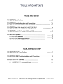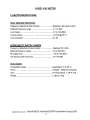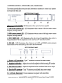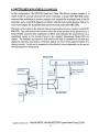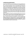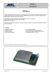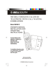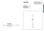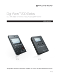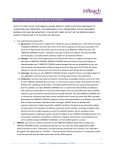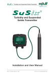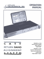
1
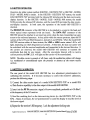
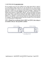
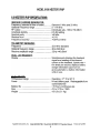
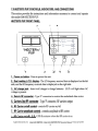
c
A
v
T
MODEL
Head
6103
End
TEst
Cable
Return
IIHECTER/'
BAND
MODEL
Carrier
Generator/
Telemetry
s
y
s
T
E
N\
6106
Receiver
Field
I'HECTER'S
Unit
PUP"
MODEL 6103 HECTER
1.0 HECTER Specifications
2.0
HECTER
Controls,
'"""""
Indicators
and
Connections
"2
3
,
4
3.0 HECTER Used With Model 6103 HECTER'S PUP
4.0 HECTER Used With Models 5112 and 819i
5.0
5.1
HECTER HECTER
5.2
Operation Line
Calibration
Voltage
Selection
...5
6
,
6
7
MODEL 6106 HECTER'S PUP
6.0
HECTER'S
PUP
Specifications
7.0
HECTER'S
PUP
Controls,
8.0
HECTER'S
8.1
HECTER'S PUP
.,"
Indicators
PUP
Operation
Automatic
and Connections
8
9
Shutoff
10
11
Applied Instruments, Inc.
Mode16103 HECTER / Model 6106 HECTER'S PUP Operation
1
Manual
Version 2/14/2001
MODEL 6103 HECTER
1.0
HECTER
DUAL
INBOUND
Frequency
Optional
SPECIFICATIONS:
RECEIVERS:
(selected
Frequency
at time
of order)
Standard
range
5 -174
Level
range
Level
accuracy
:t 0.5
Level
resolution
0.1
OUTBOUND
6 MHz
29
MHz
MHz
10 to +30
TELEMETRY
and
dB
dBmV
@ 25°
C
dB
CARRIER:
Frequency (Selected at time of order)
Standard 52.0 MHz
Optional frequency range
50 to 500 MHz
RF output level
+30 to +50 dBmV
CW spurious and harmonics
All > 60 dBc
ENCLOSURE:
Temperature
Weight
Size
Power
range
Operating
00 C to 45° C
120/240-
50/60
19" Rack
Mount,
7 LBs (3.2 Kg)
Applied
Instruments,
Inc.
Model 6103 HECTER / Model 6106 HECTER'S PUP Operation
2
Hz 0.5/0.25A
Manual
1 3/4"H,
9"0
.
Version2/14/2001
2.0 HECTER
CONTROLS
INDICATORS
AND CONNECTIONS
This section provides the instructions and information necessary to connect and operate
the Model 6103HECTER.
HECTERFRONTPANEL
2
1
3
5
4
1. Power on indicator LED -LED illuminates when power has been applied
2. LOW carrier ~resent LED -LED illuminates when a carrier of the low receive carrier
frequency is being received.
3. HIGH carrier ~resent LED -LED illuminates when a carrier of the high receive carrier
frequency is being received.
4. DATA SEND LED -LED illuminates when the forward transmitting data carrier is
being modulated with the amplitudes of the received LOW and HIGH carriers.
5. CW LED -LED illuminates when there are no LOW and HIGH carriers present,
therefore the forward transmitting data carrier is unmodulated.
HECTER
6
6. Receive
7. AmRlitude
7
In RF connecter
calibration
-Type
-Adjusts
REAR
8
'F' connector
the received
PANEL
9
10
to receive the return
amplitude
carriers.
0£ the incoming
RF carriers.
8. Data Out level control-
Adjusts the amplitude of the modulated data carrier output.
9. Data Out RF connecter
-Type
10. A.C. Cord Attachment
-Power
Applied Instruments, Inc.
'F' connector,
attachment
modulated
receptacle
data carrier
with fuse holder.
Mode16103 HECTER / Mode16106 HECTER'S PUP Operation
3
output.
Manual
Version2/14/2001
3.0 HECTER
USED WITH MODEL
6106 HECTER'S
PUP
In this configuration, the HECTER Head End Cable TEst Return system consists of a
model 6103 HECTER carrier receiver/ data modulator (to receive, measure, and transmit
the amplitude level of the RF stimulus), and a model 6106 HECTER'S PUP (to provide
inbound RF carrier stimulus, and to receive and display the modulated data carrier from
the model 6103HECTER).
The heart of the system is the Applied Instruments headend receiver/modem mode16103
HECTER. This unit receives two carriers within the return portion of the spectrum (via
the model 6106 HECTER'S PUP), measures their amplitudes in dBmV, and transmits this
measurement via a modulated carrier in the forward band back to the model 6106
HECTER'S PUP for display. The headend unit measures both carriers and data is
transmitted to the model 6106 HECTER'S PUP and displayed real-time, providing a
continuous update on return levels (approximately five times a second). Levels can be
measured or the effects of return alignment can be seen as the adjustments are being
made.
HEAD END
I
Applied Instruments, Inc.
Model 6103 HECTER / Model 6106 HECTER'S PUP Operation
4
Manual
Version2/14/2001
~.o HECTER
USED
WITH
MODELS
5112
AND
819i
In this configuration, the HECTER Head End Cable TEst Return system consists of a
model 51125 (to provide inbound RF carrier stimulus), a model 6103 HECTER carrier
receiver/ data modulator (to receive, measure, and transmit the amplitude level of the RF
stimulus), and a mode1819i Signal Level Meter with the Data Carrier Receive Option (to
receive and display the modulated data carrier from the mode16103 HECTER).
The heart of the system is the Applied Instruments headend receiver/modem model 6103
HECTER. This unit receives two carriers within the return portion of the spectrum (via a
Model 51125),measures their amplitudes in dBmV, and transmits this measurement via a
modulated carrier in the forward band to the Applied Instruments Model 819i for
display. The headend unit measures both carriers and data is transmitted to the 819i and
displayed real-time, providing a continuous update on return levels (approximately five
times a second). Levels can be measured or the effects of return alignment can be seen as
the adjustments are being made.
Applied Instruments, Inc
Mode16103 HECTER / Mode16106 HECTER'S PUP Operation
5
Manual
Version2/14/2001
5.0
HECTER
OPERATION
Operation for either system method (HECTER -HECTER'S PUP or HECTER -MODEL
51125 -MODEL 819i) is similar. In the HECTER -HECTER'S PUP system, the model
6106 HECTER'S PUP provides both the inbound RF stimulus and the data receive-anddisplay function. In the HECTER -MODEL 51125 -MODEL 819i system, the model
51125 provides the inbound RF stimulus, and the model 819i provides the data receiveand-display function. In both cases, the operation of the model 6103 HECTER is
identical.
The RECEIVE IN connector of the HECTER is to be attached to a point in the head end
where typical return spectrum levels are found. The DATA OUT connector of the
HECTER should be attached to an input tap point where the data transmitted can gain
accessto the outbound spectrum. At any point within the return spectrum, inject the RF
carriers at the LOW and HIGH frequency, typically 6 and 29 MHz. When the model 6103
HECTER receives either of these carriers, the LOW or HIGH carrier status L.E.D.s will
light, depending on which frequencies are present. At this time, the data out carrier will
be modulated with the received amplitudes and transmitted in the forward direction. If
the carriers are removed, the model 6103 HECTER will continue to transmit the
amplitudes (Lo, Lo) for one minute. After the one-minute timeout with no receive
carriers present, the CW L.E.D. will light and the carrier will be unmodulated.
NOTE: The data carrier is present at all times, only the modulation status will change
(i. e. modulated or unmodulated) upon the presence or absence of the return receive
carriers.
5.1
HECTER
CALIBRATION
The rear panel of the model 6103 HECTER has two adju~tment potentiometers for
calibrating the receivers. If it becomes necessary to correct the receiver's calibration,
perform the following steps:
1) Connect the data receive input of a model 6106 HECTER'S PUP or a model 819i
w /Data Receive capability to the data output of the model 6103 HECTER.
2) Insert into the RF IN connector a signal of known amplitude, preferable at + 10 dBm V,
at the frequency of the LO receiver .
3) Read the resulting level on the data-receiving device (i.e. the HECTER'S PUP or the
819i). Adjust, if necessary,the LO potentiometer to cause the display to read the level of
the known signal.
4) Repeat for the receiver's HI frequency. Lock the adjustment locking nuts.
Applied Instruments, Inc
Mode16103 HECIER
/ Model 6106 HECIER'S
6
PUP Operation
Manual
Version2/14/2001
5.2 HECTER LINE VOLTAGE
SELECTION
The AC receptacle can be set for the available AC line voltage, either 120VAC or 240VAC.
To set the desired voltage, remove the AC line cord from the AC input receptacle.
Remove the fuseholder cover. Remove the vertical printed circuit board with a needlenose pliers or similar tool; a fair amount of force will be necessary. Rotate the white
plastic pin so that it is pointing opposite the desired line voltage nomenclature, i.e.
opposite 120 for 120VAC or opposite 240 for 240VAC. Re-insert the printed circuit board
in the same manner it was removed, insuring the white plastic pin points to the left as
shown below. Press firmly to insure the board is fully seated. Install the proper fuse
(120VAC -l/2A, 240VAC -l/4A.) in the fuse holder cover and insert the cover onto the
AC receptacle. The white plastic pin should protrude through the hole of the fuseholder
cover to indicate the line voltage selected.
NOTE: Although there are adjustment holes for 100VAC and 220VAC, these settings are
not available on this unit. Use only 120VAC or 240VAC.
Applied Instruments, Inc.
Mode16103 HECTER I Model 6106 HECTER'S PUP Operation
'7
Manual
Version2/14/2001
MODEL 6106 HECTER'5 PUP
6.0
HECTER'S
PUP
SPECIFICATIONS:
INBOUND CARRIER GENERA TOR:
Frequency (selected at time of order)
Optional Frequency range
RF output
Amplitude stability
Spectral purity
Residual hum
Frequency accuracy
Standard 6 MHz and 29 MHz
5- 174 MHz
Individually adj., +36 to +56 dBmV
0.5 dB /setting
>60 dBc
<0.1 %
>0.01% or 5kHz
TELEMETRY
RECEIVER:
Frequency
Optional frequency range
Receive amplitude range
52.0 MHz standard
50 to 500 MHz
20 to +40 dBmV
DUAL LCD READOUT:
Display
Simultaneously
displays the head end
signal level reading of the inbound
carriers at the headend. Update rate >
five times per second, displays battery
charge information upon turn-on,
gives automatic Lo battery information
while in use.
ENCLOSURE:
Temperature range
Power
:
Operating -17° C to 50° C
Ni-cad battery pa.ck. Rechargeable from
wall transformer.
>10 hours continuous use
4"H x 1O"W x 7.250
4.5 LBs (2.1 Kg)
Battery life
Size
Weight
Applied
Instruments,
Inc.
Mode16103 HECTER / Mode16106 HECTER'S PUP Operation
8
Manual
Version2/14/2001
7.0
HECTER'S
PUP
CON.TROLS.INDICATORS.
AND
CONNEC
This section provides the instructions and information necessaryto connect and operate
the model 6106HECTER'S PUP.
HECTER'S
PUP
FRONT
PANEL
7
~
INBOUND
8
AMPL AT HEAD END
RF CARRIERS
~
6
dBmV
ON
"HECTER's"
D
PUP
D
r:;:::1
EJ
O
1
1. Power
on button
~
AC CHARGE
2
0
, RF
: IN
4
3
O
, RF
: OUT
5
-Press to power the unit.
2. Dual reading L.C.D. disRla~ -The LO frequency received data is d~splayed on the left
side, and the HI frequency received data is displayed on the right side.
3. AC charge jack -Insert
voltage is present.
4. Data In RF connecter
5. Carriers
6.
-Type 'F' connector to receive the modulated data carrier.
Out RF connecter
RF Carrier
7. RF Carrier
on/off
control-
am~litude
wall charger to charge batteries. L.E.D. will light when AC
-Type
controls
control-
'F' connector,
RF carrier
controls
RF carriers output.
on/ off.
amplitude
of RF carrier.
8. RF Carrier on/off L.E.D.-LED illuminates when the RF carrier is on.
Applied
Instruments,
Inc.
Model 6103 HECTER / Model 6106 HECTER'S PUP Operation
9
Manual
Version211412001
8.0 HECTER'S
PUP OPERATION
In the HECTER -HECTER'S PUP system, the HECTER'S PUP provides both the inbound
RF stimulus and the data receive-and-display function. The RF IN connector of the
model 6016 HECTER'S PUP is to be attached to a point in the system where the
outbound data transmission can be found. The RF OUT connector of the model 6016
HECTER'S PUP should be attached to a input tap point to feed the inbound RF carriers to
the model 6013 HECTER at the headend When the model 6103 HECTER receives either
of these carriers, the LOW or HIGH carrier status L.E.D.s will light, depending on which
frequencies are present. At this time, the data out carrier will be modulated with the
received amplitudes and transmitted in the forward direction. If the carriers are
removed, the model 6103 HECTER will continue to transmit the amplitudes (Lo, Lo) for
one minute. After the one minute timeout with no receive carriers present, the CW L.E.D.
will light and the carrier will be unmodulated.
NOTE: The data carrier is present at all times, only the modulation status will change
(i.e. modulated or unmodulated) upon the presence or absence of the return receive
carriers.
The model 6106 HECTER'S PUP will display no Sig when there does not exist a data
carrier of sufficient signal strength. If a signal of sufficient strength is present, but not
modulated with data, no Dat will be displayed. Upon turn on, the battery level will be
displayed for four seconds, or until another button is pressed. To determine the battery
voltage when using the model 6106HECTER'S PUP, simply press the on/ off button twice
(to turn the unit off, then back on). The battery level will again be displayed. Lo bA T
will flash when the battery is low.
NOTE: When the unit is powered up, both RF carriers will be OFF.
Displays showing: no data, no signal, battery level, and low battery level
Applied Instruments, Inc
Model 6103 HECTER / Model 6106HECTER'S PUP Operation Manual
10
Version2/14/2001
8.1
HECTER'S
PUP
AUTOMATIC
SHUTOFF
The model 6106 HECTER'S PUP will automatically shut off after approximately four
minutes. This is to conserve battery life in the event the unit is accidentally left in the ON
state. At times, however, the unit may wish to be left unattended while the RF carriers
are used in system troubleshooting. The four minute time out may be disabled and
replaced with a 120 minute timeout by using a special power-up method. To select the
120 minute auto shutoff timeout, press and hold either RF carrier ON / OFF button before
applying power via the POWER button. Keep the RF carrier ON/OFF button pressed
while applying power. The unit will sensethe closed switch and select the 120 minute
auto shutoff mode. The LCD display will show 120 for a short period of time to indicate
the longer shutoff period. The 120 minute auto shutoff timeout must be selected each
time this feature is desired; simply powering the unit normally (without pressing and
holding either RF carrier button) will power up the unit using the normal 4 minute auto
shutoff timeout.
NOTE: The initial RF carrier button press-and-hold will NOT cause the carrier to be
energized. This is to prevent the carrier from being applied simply upon powering the
unit. The held button needs to be released and re-pressed to activate the RF carrier.
NOTE: To protect the battery from excess discharge, a low battery shutoff has been
incorporated into the unit.
This feature shuts the unit off in the event the battery
becomes too discharged to properly power the unit. Also, NI-CAD batteries can have
their useful life shortened by discharging them beyond their design limits. If the 120
minute auto shutoff has been selected, the unit will still "LOW BATTERY" shut off if the
battery level fall too low within the selected 120 minutes.
Applied Instruments, Inc.
Mode16103 HECTER / Mode16106 HECTER'S PUP Operation Manual
11
Version2/14/2001
Hecter Pup Operation Manual
Part 078-00130