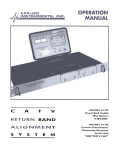
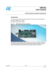
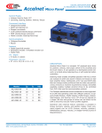
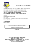
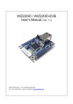
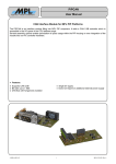
1
PIPVIN -x User Manual High-Tech • Made in Switzerland PIPVIN -x PIPVIN is designed for the PIPs from MPL. A 50W-DC/DC-Converter gives the possibility to extend the supply voltage range of the PIPs from 8-28V to 18-48V1. PIPVIN-4 with 12V Output is used for PIPs without UPS, PIPVIN-3 (24V Output) is used for PIPs with UPS. At the publication date of this manual, the following MPL products are supported: PIP5, PIP6, PIP7, PIP8, PIP9, PIP10, PIP11, PIP20 PIP9-E, PIP10-E, PIP11-E This document describes the PIPVIN-x module. Its purpose is to give all the needed information to handle the board successfully. ● Features: ● ● ● ● Isolated 50W-Output Efficiency to 85% Remote Sensing Short Circuit Protection ● ● ● ● Over voltage protection Passive Cooling with 5-sided metal case Logic Input to switch DC/DC-Converter on/off Temperature range: -40°C-75°C Note 1: Other input ranges are available on demand (for example 9-36V). 2008 by MPL AG 1 MEH-10127-001 Rev. C PIPVIN -x User Manual High-Tech • Made in Switzerland TABLE OF CONTENTS 1 INTRODUCTION............................................................................................................. 3 1.1 ABOUT THIS MANUAL......................................................................................................... 3 1.2 SAFTY PRECAUTIONS AND HANDLING............................................................................ 3 1.3 ELECTROSTATIC DISCHARGE (ESD) PROTECTION........................................................ 3 1.4 EQUIPMENT SAFETY........................................................................................................... 3 1.5 MANUAL REVISIONS............................................................................................................ 4 1.5.1 RELATED PRODUCTS.................................................................................................. 4 1.5.2 REVISION HISTORY..................................................................................................... 4 2 GENERAL INFORMATION AND SPECIFICATIONS...................................................... 5 2.1 TECHNICAL SPECIFICATIONS............................................................................................ 5 2.2 DIMENSIONS & PART LOCATIONS..................................................................................... 6 2.2.1 DIMENSIONS TOP VIEW:............................................................................................ 6 2.2.2 FORMFACTOR:............................................................................................................. 6 2.3 STANDARDS COMPLIANCE................................................................................................ 7 2.3.1 EMC............................................................................................................................... 7 2.3.2 Environmental................................................................................................................. 7 2.3.3 Safety............................................................................................................................. 7 2.3.4 Type Approval................................................................................................................ 7 3 CONNECTOR................................................................................................................. 8 3.1 DESCRIPTION CONNECTOR............................................................................................... 3.2 PINOUT.................................................................................................................................. 3.3 OPTIONAL SIGNALS............................................................................................................ 3.3.1 SENSE+/SENSE-........................................................................................................... 3.3.2 OFF#.............................................................................................................................. 8 8 9 9 9 4 OVERVIEW AVAILABLE PIPVIN VERSIONS.............................................................. 10 5 COPYRIGHT................................................................................................................. 12 6 DISCLAIMER................................................................................................................ 12 7 TRADEMARKS............................................................................................................. 12 8 SUPPORT..................................................................................................................... 12 8.1 SERIAL NUMBER AND REVISION..................................................................................... 12 8.2 CONTACT MPL AG............................................................................................................. 12 2008 by MPL AG 2 MEH-10127-001 Rev. C PIPVIN -x User Manual High-Tech • Made in Switzerland 1 INTRODUCTION 1.1 ABOUT THIS MANUAL This manual provides all the information necessary to handle and configure the PIPVIN-4 or PIPVIN-3. The manual is written for technical personnel responsible for integrating the PIPVIN into their systems. 1.2 SAFTY PRECAUTIONS AND HANDLING For personal safety and safe operation of the PIPVIN, follow all safety procedures described here and in other sections of the miscellaneous manual. ● Remove power from the system before installing (or removing) the PIPVIN, to prevent the possibility of personal injury (electrical shock) and / or damage to the product. ● Handle the product carefully; i.e. dropping or mishandling the PIPVIN can cause damage to assemblies and components. ● Do not expose the equipment to moisture. WARNING There are no user-serviceable components on the PIPVIN-4/-3. 1.3 ELECTROSTATIC DISCHARGE (ESD) PROTECTION Various electrical components within the product are sensitive to static and electrostatic discharge (ESD). Even a small static discharge can be sufficient to destroy or degrade a component's operation! With an open housing, do not touch any electronic components. Handle or touch only the unit chassis. 1.4 EQUIPMENT SAFETY Great care is taken by MPL AG that all its products are thoroughly and rigorously tested before leaving the factory to ensure that they are fully operational and conform to specification. However, no matter how reliable a product, there is always the remote possibility that a defect may occur. The occurrence of a defect on this device may, under certain conditions, cause a defect to occur in adjoining and/or connected equipment. It is your responsibility to protect such equipment when installing this device. MPL accepts no responsibility whatsoever for such defects, however caused. 2008 by MPL AG 3 MEH-10127-001 Rev. C PIPVIN -x User Manual High-Tech • Made in Switzerland 1.5 MANUAL REVISIONS 1.5.1 RELATED PRODUCTS Manual Revisions A B C Related To • PIPVIN-4 / PIPVIN-3 • PIPVIN-4 / PIPVIN-3 • PIPVIN-4 / PIPVIN-3 1.5.2 REVISION HISTORY Manual Revisions A B Date Description 2006-11-23 2007-02-23 Initial release of this document. C 2008-02-12 2008 by MPL AG • • • • • Corrected Storage temperature range on page 5 Added relative humidity on page 5 Added chapter “standards compliance” on page 7 Corrected drawing (dimensions and part locations) on page 6 Added PIP20, PIP9-E, PIP10-E and PIP11-E as supported products 4 MEH-10127-001 Rev. C PIPVIN -x User Manual High-Tech • Made in Switzerland 2 GENERAL INFORMATION AND SPECIFICATIONS 2.1 TECHNICAL SPECIFICATIONS Input: Input Voltage Range: Input Current (Full Load): Input Current (No Load): Under voltage Lockout: Output: Output Voltage Trim: Initial Set Accuracy: Load Regulation: Ripple & Noise: Short Circuit Protection General: Switching Frequency: Isolation Resistance: 18-48V 2'510 mA 50 mA 9-36V, power up 8.8V, power down 8.0V 18-48V, power up 17.0V, power down 16.0V +/- 10% +/- 1% max. +/- 0.2% max. 1% max pk-pk Continuous Efficiency: 300 kHz typ. 1500 VDC Input to Output 1500 VDC Input to Case 1500 VDC Output to Case 85% typ. Operating Ambient Temperature: Storage Ambient Temperature: -40°C to +75°C -45°C to +85°C Relative humidity: 5% to 95% RH non condensing Note: Operating Ambient Temperature can only be guaranteed when PIPVIN is mounted on the cover of the case! 2008 by MPL AG 5 MEH-10127-001 Rev. C PIPVIN -x User Manual High-Tech • Made in Switzerland 2.2 DIMENSIONS & PART LOCATIONS All components are on the top layer. 2.2.1 DIMENSIONS TOP VIEW: M3 R1 R2 M4 R3 R4 M8 M1-M4: 3.3mm M5-M8: M3-Thread PIPVIN R5 50.80mm. U1 M5-M8 depending on DC/ DC-Converter R6 95.00mm. U3 C1 M6 48.30mm. M1 18.00mm. 34.10mm. M5 TS1 100.00mm. M7 M2 F1 J1 7.00mm. 8.40mm. 58.00mm. 65.00mm. 2.2.2 FORMFACTOR: • • • Length: Width: Height: 2008 by MPL AG 100mm 65mm 17mm 6 MEH-10127-001 Rev. C PIPVIN -x User Manual High-Tech • Made in Switzerland 2.3 STANDARDS COMPLIANCE The PIPVIN -x is designed to meet or exceed the most common industry and military standards. Particular references are: 2.3.1 EMC • EN 55022 Class B (Information technology equipment - Radio disturbance characteristics - Limits and methods of measurement) • EN 55024 (Information technology equipment - Immunity characteristics - Limits and methods of measurement) • EN 61000-4-1 (Electromagnetic compatibility (EMC) -- Part 4-1: Testing and measurement techniques Overview of IEC 61000-4 series) • EN 61000-4-2 Level 3, Criterion B (Electromagnetic compatibility (EMC) -- Part 4-2: Testing and measurement techniques - Electrostatic discharge immunity test) • EN 61000-4-3 Level 3, Criterion A (Electromagnetic compatibility (EMC) -- Part 4-3: Testing and measurement techniques - Radiated, radio-frequency, electromagnetic field immunity test) • EN 61000-4-4 Class 3 (Electromagnetic compatibility (EMC) -- Part 4-4: Testing and measurement techniques - Electrical fast transient/burst immunity test) • EN 61000-4-5 Class 3 (Electromagnetic compatibility (EMC) -- Part 4-5: Testing and measurement techniques - Surge immunity test) • EN 61000-4-6 Class 3 (Electromagnetic compatibility (EMC) -- Part 4-6: Testing and measurement techniques - Immunity to conducted disturbances, induced by radio-frequency fields) • EN 61000-6-1 (Electromagnetic compatibility (EMC) -- Part 6-1: Generic standards - Immunity for residential, commercial and light-industrial environments) • EN 61000-6-2 (Electromagnetic compatibility (EMC) -- Part 6-2: Generic standards - Immunity for industrial environments) • EN 61000-6-3 (Electromagnetic compatibility (EMC) -- Part 6-3: Generic standards - Emission standard for residential, commercial and light-industrial environments) • EN 61000-6-4 (Electromagnetic compatibility (EMC) -- Part 6-4: Generic standards - Emission standard for industrial environments) • MIL-STD-461E (REQUIREMENTS FOR THE CONTROL OF ELECTROMAGNETIC INTERFERENCE CHARACTERISTICS OF SUBSYSTEMS AND EQUIPMENT) 2.3.2 Environmental • EN 50155 (Railway applications - Electronic equipment used on rolling stock) • MIL-STD-810-F (ENVIRONMENTAL ENGINEERING CONSIDERATIONS AND LABORATORY TESTS) 2.3.3 Safety • EN 60601-1 (Medical electrical equipment -- Part 1: General requirements for safety) • EN 60950 Class III (Information technology equipment - Safety) 2.3.4 Type Approval • EN 60945 Protected Equipment (Maritime navigation and radiocommunication equipment and systems General requirements - Methods of testing and required test results) • IACS E10 (Test Specification for Type Approval) 2008 by MPL AG 7 MEH-10127-001 Rev. C PIPVIN -x User Manual High-Tech • Made in Switzerland 3 CONNECTOR 3.1 DESCRIPTION CONNECTOR The connector is a 2x10pin 2.54mm header. Connector: Samtec, IPL1-110-01-S-D-RA Counterpart: Housing: Samtec, IPD1-10-D Contacts: Samtec, CC79L-2024-01-S 3.2 PINOUT Pin Number Signal Description 1 VIN_GND 2 VIN 3 VIN_GND 4 VIN 5 VIN_GND 6 VIN 7 OFF# 8 n.c. - 9 n.c. - 10 n.c. - 11 n.c. - 12 n.c. - 13 SENSE+ Pos. Input for remote sensing 14 SENSE- Neg. Input for remote sensing 15 VOUT_GND 16 VOUT 17 VOUT_GND 18 VOUT 19 VOUT_GND 20 VOUT Pin Out Input Gnd Input Voltage 18-48V 1 Input Gnd Input Voltage 18-48V 1 Input Gnd Input Voltage 18-48V 1 Open collector input, Off < 0.8V 19 17 15 13 11 9 7 5 3 1 20 18 16 14 12 10 8 6 4 2 Output Gnd Output Voltage 12V or 24V 2 Output Gnd Output Voltage 12V or 24V 2 Output Gnd Output Voltage 12V or 24V 2 Notes: 1 Depending of the DC/DC-Converter on the board, other input voltage ranges are available on demand 2 Depending of the DC/DC-Converter on the board (PIPVIN-4: 12V Output, PIPVIN-3: 24V Output) 2008 by MPL AG 8 MEH-10127-001 Rev. C PIPVIN -x User Manual High-Tech • Made in Switzerland 3.3 OPTIONAL SIGNALS 3.3.1 SENSE+/SENSEThe sense inputs are needed for remote sensing. With remote sensing, the output voltage is regulated on the load but not directly on the output pin of the DC/DC-Converter. The voltage drop, which depends of the load (i.e. output current) and the length of the output path (cables), can be compensated on this way. 3.3.2 OFF# The OFF# - Signal is an open collector input, which is used, to switch the DC/DC-Converter off. When this signal is below 0.8V, DC/DC-Converter is off. To switch the DC/DC-Converter on, this signal has to be driven over 0.8V or can be left open. 2008 by MPL AG 9 MEH-10127-001 Rev. C PIPVIN -x User Manual High-Tech • Made in Switzerland 4 Overview available PIPVIN versions • • • PIPVIN-4: 12V/50W-Output, 18-48V Input voltage PIPVIN-3: 24V/50W-Output, 18-48V Input voltage PIPVIN-x: 2008 by MPL AG 10 MEH-10127-001 Rev. C PIPVIN -x User Manual High-Tech • Made in Switzerland This page intentionally left blank. 2008 by MPL AG 11 MEH-10127-001 Rev. C PIPVIN -x User Manual High-Tech • Made in Switzerland 5 COPYRIGHT Copyright © 2008 by MPL AG Elektronikunternehmen. All rights are reserved. Reproduction of this document in part or whole, by any means is prohibited, without written permission from MPL AG Elektronikunternehmen. 6 DISCLAIMER MPL AG has fully tested the PIPVIN and reviewed the documentation. However, MPL AG makes no warranty or representation, either expressed, or implied, with respect to this product, its quality, performance, merchantability, or fitness for a particular purpose. In no event will MPL AG be liable for direct, indirect, special, incidental, or consequential damages resulting from any defect in the product or its documentation, even if advised of the possibility of such damages. In particular MPL AG shall have no liability for any parts connected to this product. MPL AG reserves the right to make changes to any product herein to improve reliability, function or design. 7 TRADEMARKS Brand or product names are trademarks and registered trademarks of their respective holders. 8 SUPPORT 8.1 SERIAL NUMBER AND REVISION For support it is needed that you know the product name, the product variant and the serial number of your PIPVIN. Please have a look at the label on the bottom of the PIPVIN PCB for this. Product Name Product Variant Serial Number PIPVIN-4 SN: 501 (A) Figure 1: PIPVIN Label 8.2 CONTACT MPL AG In case of general information questions please feel free to contact us at our homepage (www.mpl.ch) or per email ([email protected]). In case of sales information questions please send an email to [email protected]. If you have a technical problem with a PIPVIN, first please read this manual carefully. If you can’t solve the problem on your own you can contact us for technical support per email at [email protected]. Our local Distributor: 2008 by MPL AG 12 MEH-10127-001 Rev. C