1
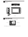
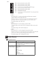
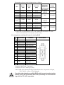
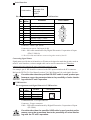
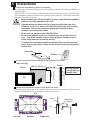
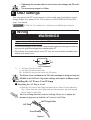
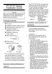
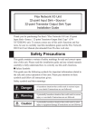
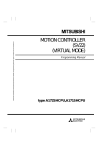
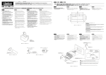
FP3700-T41 Installation Guide
WARNINGS
• When connecting the FP3700-T41 (hereafter referred to as the "FP")'s power
cord terminals to the FP unit's Terminal Block, check first that the FP unit's
power supply is completely turned OFF, via a breaker, or similar unit.
• Whenever changing the backlight, to prevent electric shocks and burns, be
sure to unplug the FP unit's power cord and wear protective gloves.
• Do not open or remodel the FP unit, since it may lead to a fire or electric
shock.
• Do not use power beyond the FP unit's specified voltage range. Doing so
may cause a fire or an electric shock.
• Do not use the FP in an environment where flammable gases are present,
since operating the FP may cause an explosion.
• Do not use the FP as a warning device for critical alarms that can cause
serious operator injury, machine damage or production stoppage. Critical
alarm indicators and their control/activator units must be designed using
stand-alone hardware and/or mechanical interlocks.
• Do not use FP touch panel switches in life-related or important disaster
prevention situations. For safety related switches, such as an emergency
switch, be sure to use a separate mechanical switch.
• After the FP’s backlight burns out, unlike the FP’s “Standby Mode”, the
touch panel is still active. If the operator fails to notice that the backlight is
burned out and touches the panel, a potentially dangerous machine missoperation can occur. Therefore, do not use FP touch switches for the control of any equipment safety mechanisms, such as Emergency Stop
switches, etc. that protect humans and equipment from injury and damage.
If your FP's backlight suddenly turns OFF, use the following steps to determine if the backlight is actually burned out.
1) If your currentFP application is not set to turn the backlight OFF, and the
screen has gone blank, your backlight is burned out.
2) If your current FP application is set to turn the backlight OFF, if touching
the screen does not cause the display to reappear, your backlight is burned
out.
• To prevent operator injury or machine damage, be sure to design your machine operation system so that the machine will not malfunction due to a
communication fault between the FP and its host controller.
• The FP is not appropriate for use with aircraft control devices, aerospace
equipment, central trunk data transmission (communication) devices, nuclear
power control devices, or medical life support equipment, due to these devices' inherent requirements of extremely high levels of safety and reliability.
• When using the FP with transportation vehicles (trains, cars and ships),
disaster and crime prevention devices, various types of safety equipment,
non-life support related medical devices, etc., redundant and/or failsafe system designs should be used to ensure the proper degree of reliability and
safety.
To prevent this unit from malfunctioning:
• Do not strike the FP touch panel with a hard or heavy object, or press on the
touch panel with too much force, since it may damage the display.
• Do not install the FP where the temperature will exceed the specified range.
• Be sure that water, liquids or metal particles do not enter the FP, since it may
cause a malfunction or a short circuit.
• Avoid installing the FP where sudden, large changes in temperature may occur.
These changes may cause condensation to form inside the unit, possibly causing a malfunction.
• To prevent excessive heat from building up inside the FP, do not install it where its
ventilation holes may be blocked. Also, do not install or store the FP near high
temperature equipment.
• Do not install or store the FP where direct sunlight or high levels of dust exist.
• Since the FP is a precision instrument, do not install or store it where either
strong shocks or excessive vibration may occur.
• Do not install or store the FP in an area containing chemicals or chemical fumes.
• Do not use paint thinner or organic solvents to clean the FP unit's case or screen.
• After turning the FP OFF, be sure to wait a few seconds before turning it ON
again. If the FP is started too soon, it may not start up correctly.
UL/c-UL (CSA) Application Notes
The FP3700-T41 is a UL/c-UL (CSA) listed product. (UL File No.E220851)
This unit conforms as a product to the following standards:
UL508 Industrial Control Equipment
CAN/CSA C22.2 No.14-M1995 Industrial Control Equipment
FP3700-T41 (UL Registration Model: 3180040-01)
<Cautions>
• The FP must be used as a built-in component of an end-use product.
• This unit should be installed in the front face of a metal panel.
• If this unit is installed so as to cool itself naturally, be sure to install it
in a vertical panel. Also, be sure that the FP unit is mounted at least
100 mm away from any adjacent structures or equipment. If these
requirements are not met, the heat generated by the FP unit’s internal
components may cause the unit to fail to meet UL/c-UL standard
requirements.
CE Marking Notes
The FP3700-T41 is a CE marked product that conforms to EMC directives
and Low Voltage directives EN55011 Class A, EN61000-6-2 and
EN60950-1 First Edition.
* For detailed CE marking information, please contact your local FP distributor.
<Cautions>
• The FP unit is intended for indoor use only.
• When an end-user product will include the FP, be sure to design the FP unit's
power cut-off switch as a separate disconnect device and locate it where the
operator can easily reach it.
• Be sure the unit the FP is built into uses an EN60950-1 approved structure.
Package Contents
The following items are included in the FP unit's package. Before
using the FP, please confirm that all items listed here are present.
FP unit
(FP3700-T41)
CD-ROM(1)
Contains the FP3700-T41 User Manual
Installation Gasket (1)
Installation Brackets (4/set, 2sets)
FP3700-T41 Installation Guide (1)
(this manual)
AC Power Cord(1)
Cord Clamp(1)
USB Cable Strap(1)
This unit has been carefully packed, with special attention to quality. However, should you find anything damaged or missing, please
contact your local FP distributor immediately.
The Power Cord included in the FP unit's package is designed only for
AC100V or AC115V use. Any other voltage will require a different cord.
Options
Cables
Maintenance Parts
1
Touch panel driver software
Part Names
Front View
I
A, B
Rear View
C
D E F G
Bottom View
H
A: TFT Color LCD
Acts as a display monitor for your host.
B: Touch Panel
Allows you to switch screens or write data to the
host.
C: AC Connector
Provides the input and ground terminals for a
power cable.
D: Setting Switch (Dip switches)
Used to change the settings of each operation
mode.
E: VGA Interface (analog RGB) Connector
Connector for analog RGB interface
F: DVI-D Interface Connector
Connector for DVI-D interface
G: RS-232C Connector
Connector for RS-232C (serial) interface. Used for
sending touch panel data to the host, and for receiving commands from the host.
H: USB Connector
Connector for USB interface. Used for both sending touch panel data to the host, and receiving
commands from the host.
I: Front LED
Used to indicate the condition of the power supply,
a backlight burnout or image signal input.
2 Dimensions
Unit:mm [in]
383[15.08]
Top View
294[11.57]
44[1.73]
282[11.1]
395[15.55]
5[0.2]
34.9[1.37]
60 [2.36]
Side View
Front View
3 Dip Switches
The dip switches are under the cover shown below.
Rear view
Dip-swiches
After changing your FP unit's Dip Switch settings, please reboot your FP.
SW1
8
7
6
5
4
3
2
1
SW1-8
SW1-7
SW1-6
SW1-5
SW1-4
SW1-3
SW1-2
SW1-1
ON
Reserved (Set this switch to OFF)
Reserved (Set this switch to OFF)
Reserved (Set this switch to OFF)
Switch between analog RGB and DVI-D input
Reserved (Set this switch to OFF)
Reserved (Set this switch to OFF)
Display/hide the OSD
Switch between USB and RS232C for touch panel data
transmission.
• SW1-1
Dip Switch SW1-1 is used to set the touch panel data input (command
control) method to either USB or RS-232C.
When the switch is set to OFF, data output and command input/output are
performed via RS-232C. When the switch is set to ON, USB is used.
The default setting is OFF. (RS-232C)
• SW1-2
Dip Switch SW1-2 is used to display or hide the OSD.
To hide the OSD, set the switch to ON. To display the OSD, set the switch
to OFF.
The default setting is OFF. (OSD is displayed.)
• SW1-5
Dip Switch SW1-5 is used to change the image input method.
When the switch is set to ON, DVI-D image input method is used. When the
switch is set to OFF, the analog RGB image input method is used.
The default setting is OFF. (Analog RGB is used.)
4 Interfaces
Analog RGB Interface
Input signal type
Analog RGB
Input signal characteristic Image signal: analog RGB
Synchronous signal: T TL level, negative true or positive true
Scanning type: non-interlace
Setting by OSD
CONT RAST
(On Screen Display)
BLACK LEVEL
H-POS
V-POS
OSD H-POSIT ION
PHASE
BACKLIGHT
DEFAULT (ALL CLEAR)
The number of dots (pixels) displayed are as follows:
Size
H Sync.
(kHz)
V Sync.
(Hz)
Dot Clock
(MHz)
640×400
640×400
640×480
640×480
640×480
24.827
31.469
31.469
37.500
35.000
56.000
70.000
59.992
75.000
66.667
21.053
25.175
25.175
31.500
30.240
720×400*1
31.469
70.000
28.320
800×600
800×600
1024×768
1024×768
1024×768
37.879
46.875
48.363
56.476
60.023
60.317
75.000
60.004
70.069
75.029
40.000
49.500
65.000
75.000
78.750
Screen
Resolution
Expansion
(H: Horizontal)
(V: Vertical)
Display
Resolution
×1.6 (H)
×1.92 (V)
1024×767
×1.6
1024×768
×1.42 (H)
×1.92 (V)
1023×767
×1.28
1024×768
×1.0
1024×768
*1 When you use this resolution, select "720 x 400 Display Resolution 720 x 400
DSP" in the OSD (On Screen Display) system setting.
Pin Assignments and Signal Names for Analog RGB
Pin
No.
1
2
3
4
5
6
7
8
9
10
11
12
Analog R
Analog G
Analog B
Reserved
Digital grounding
Return R
Return G
Return B
Reserved
Digital grounding
Reserved
Reserved
13
H. SYNC
14
V. SYNC
15
Reserved
Signal Name
Condition
R signal input
G signal input
B signal input
NC (spare for input)
Digital signal GND
R signal GND
G signal GND
B signal GND
NC (spare for input)
Digital signal GND
NC (spare for input)
NC (spare for input)
Horizontal
synchronous signal
Vertical synchronous
signal input
NC (spare for input)
Pin Location
15
5
11
1
Connector:Mini Dsub 15 pin male
Connector set screw: Inch type (4-40)
Cable: RGB cable manufactured by Digital Electronics Corporation of Japan,
FP-CV02-45 <4.5m> (VGA standard)
If a cable other than the specified RGB cable is used, product performance cannot be guaranteed due to the possibility of noise interfering with the FP unit's operation.
DVI-D Interface
Input signal type
Setting by OSD
(On Screen Display)
DVI-D
H-POS
V-POS
BACKLIGHT
DEFAULT (ALL CLEAR)
The number of dots (pixels) displayed are as follows:
Size
H Sync.
(kHz)
V Sync.
(Hz)
Dot Clock
(MHz)
640×400
640×400
640×480
640×480
640×480
24.827
31.469
31.469
37.500
35.000
56.000
70.000
59.992
75.000
66.667
21.053
25.175
25.175
31.500
30.240
720×400*1
31.469
70.000
28.320
800×600
800×600
1024×768
1024×768
1024×768
37.879
46.875
48.363
56.476
60.023
60.317
75.000
60.004
70.069
75.029
40.000
49.500
65.000
75.000
78.750
Screen
Resolution
Expansion
(H: Horizontal)
(V: Vertical)
Display
Resolution
×1.6 (H)
×1.92 (V)
1024×767
×1.6
1024×768
×1.42 (H)
×1.92 (V)
1023×767
×1.28
1024×768
×1.0
1024×768
*1 When you use this resolution, select "720 x 400 Display Resolution 720 x 400
DSP" in the OSD (On Screen Display) system setting.
Pin Assignments and Signal Names for DVI-D
Pin
No.
1
2
3
4
5
6
7
8
9
10
11
12
Signal Name
T MDS DAT A2T MDS DAT A2+
T MDS DAT A2/4 SHIELD
NC
NC
DDC Clock
DDC Data
NC
T MDS DAT A1T MDS DAT A1+
T MDS DAT A1/3 SHIELD
NC
Pin
No.
13
14
15
16
17
18
19
20
21
22
23
24
Signal Name
NC
NC
GND (+5V)
Hot Plug Detect
T MDS DAT A0T MDS DAT A0+
T MDS DAT A0/5 SHIELD
NC
NC
T MDS CLOCK SHIELD
T MDS CLOCK+
T MDS CLOCK-
Pin Location
17
1
24
7
Connector: DVI-D 24-pin male
Connector set screw: Inch type (4-40)
Cable: DVI-D cable manufactured by Digital Electronics Corporation of Japan
(FP-DV01-50 <5 m>, FP-DV01-100 <10 m>)
• The FP-DV01-100 can be used only when connected to a PS-2000B
unit. When using the FP-DV01-100, be sure to turn the PS-2000B's
internal dipswitch 4 ON. (When using the FP-DV01-50, turn this
switch OFF.)
• If a cable other than the specified DVI-D cable is used, product
performance cannot be guaranteed due to the possibility of noise
interfering with the FP unit's operation.
Serial Interface
Baud rate: 9600 bps
Data length: 8 bits
Parity: none
Stop bit: 1
Serial Interface
Pin Assignments and Signal Names for Serial Interface
Pin Signal
Condition
No. Name
1
CD
Carrier Detect *1
2
RD
Receive Data (FP->Host)
3
SD
Send Data (FP<-Host)
4
DT R
5
GND
6
DSR
7
8
9
RS
CS
NC
Pin Location
Data T erminal Ready *1
Ground
6
9
Data Set Ready *1
Request to Send (FP<-Host)
Clear to Send (FP->Host)
(Used internally)
1
5
Connector : Dsub 9 pin female
Connector set screw : Inch type (4-40)
Cable : SIO cable manufactured by Digital Electronics Corporation of Japan
(FP61V-IS00-O)
*1 The CD, DTR, and DSR are connected together inside of the FP.
Concerning Signal Names
Signal names used for the serial interface on FP units are designed to match the pin order used on
most PC serial interfaces, so that a straight cable can be used to connect the two. Therefore,
connect each pin's signal to the same signal name on the PC side.
For example, pin #2 'RD' should be connected to the 'RD' input terminal on the PC's connector.
Refer to the FP3700-T41 User Manual's section "2-4 Cable Diagrams" for each signal's direction.
If a cable other than the specified RS-232C cable is used, product performance cannot be guaranteed due to the possibility of noise interfering with the FP unit's operation.
USB Interface
Pin Assignments and Signal Names for USB Interface
Pin
NO.
1
2
3
4
Signal
Name
USB1-5V
USBD1(-)
USBD1(+)
GND
Condition
+5VIN
USBdata(-)
USBdata(+)
Ground
Pin Location
2
1
3
4
Communication : Low speed Device
Connector : B type connector
Cable : USB cable manufactured by Digital Electronics Corporation of Japan
(FP-US00)
If a cable other than the specified USB cable is used, product performance cannot be guaranteed due to the possibility of noise interfering with the FP unit's operation.
5 Installation
Confirm the Installation Gasket's Positioning
It is strongly recommended that you use the gasket. It absorbs vibration in addition to
repelling water.
Place the FP on a level surface with the display panel facing downward. Check that the
FP’s installation gasket is seated securely into the gasket’s groove, which runs around the
perimeter of the panel’s frame.
• Before installing the FP into a cabinet or panel, check that the installation
gasket is securely attached to the unit.
• A gasket which has been used for a long period of time may have
scratches or dirt on it, and could have lost much of its dust and drip
resistance. Be sure to change the gasket periodically or when
scratches or dirt become visible.
• Be sure to use gasket model CA3-WPG15-01.
• Be sure the gasket's seam is not inserted into any of the unit's corners, only in the straight sections of the groove. Inserting it into a
corner may lead to its eventually tearing.
• To ensure the installation gasket's maximum level of moisture resistance, be sure the gasket's seam is inserted as shown into the panel's
bottom face.
Rear face
Gasket
FRONT
FP
282.5+1
0
[11.12+0.04
]
0
Create a Panel Cut and insert the FP into the panel from the front
Unit: mm [in]
Panel
383.5 +10 [15.1+0.04
] under 4-R3
0
Panel
Panel thickness
1.6mm[0.06in] to
10mm[0.39in]
FP
Attach the Installation Fasteners from Inside the Panel
The following figures show the eight(8) fastener insertion slot locations. Insert each
fastener's hook into the slot and tighten it with a screwdriver.
Top
Panel
Insertion Slots
FP
Left side
Bottom
Right side
Installation
fastener
• Tightening the screws with too much force can damage the FP unit's
case.
• The necessary torque is 0.5N•m.
6 OSD settings
You can operate the FP screen menus via the touch panel, and adjust screen
image display to a minute level. The feature is called OSD (On Screen Display). For details,
FP3700-T41 User Manual 3.3.3 Calibration of OSD Display Position
7 Wiring
WARNINGS
• To avoid an electric shock, when connecting the FP's power cord terminals to
the power terminal block, confirm that the FP's power supply is completely turned
OFF, via a breaker, or similar unit.
• To avoid the dangers of fire, electric hazards and equipment damege, be sure to
use only the specified voltage when operating the FP.
• Since there is no power switch on the FP unit, be sure to attach a breaker-type
switch to its power cord.
N
*1
L
FG
AC Connector*1
L : AC Input Terminal-live line
N : AC Input Terminal-neutral line
FG : Ground Terminal connected to the FP chassis
The Power Cord included in the FP unit's package is designed only for
AC100V or AC115V use. Any other voltage will require a different cord.
Installing the AC Power Cord Clamp
Attaching the AC Power Cord
1) Open the AC Power Cord Clamp and insert the AC Power Cord as shown in
fig. 1. Then, close the Cord Clamp until it clicks into place and locks around
the AC Power Cord Collar.
The Cord Clamp has four teeth for locking. These are to adjust the
amount of grip used to hold the AC Power Cord Collar.
AC Plug Collar
AC Plug
Cord Clamp
Figure 1
2) Connect the AC plug to the FP unit’s AC connector, as shown in fig. 2.
AC Plug
AC Connector
Cord Clamp
Lock Pin Hole
Cord Clamp Lock Pin
AC Plug Collar
Lock Tab Release
Figure 2
3) Insert the Cord Clamp Lock Pin into the FP unit’s Lock Pin Hole.
4) Adjust the Lock Pin’s Lock Tab length until it is securely held.
Removing the AC Power Cord
5) While lifting up on the Lock Pin’s Lock Tab Release, pull the AC Plug, Plug
Collar and Cord Clamp backwards to disconnect it from the FP unit.
6) Open the Cord Clamp (opposite of step 1) and remove the AC Power Cord
from the Cord Clamp.
8 Using the USB Cable Strap
USB Cable Strap Attachment Procedure
1) Connect the USB cable to the connector.
2) Insert the cable strap into the cable strap holder as shown in figure 1, and
tighten the strap until the cable is secured in place.
USB Cable
USB cable strap
Stopper
USB cable strap holder
Figure 1
USB Cable Strap Removal Feature
3) Push in the cable strap's stopper until the cable strap band is unlocked, then
remove the band.
4) Disconnect the USB cable.
9 Power Supply Cautions
Please pay special attention to the following instructions when connecting
the power cord terminals to the FP unit.
• If the power supply voltage exceeds the FP unit's specified range, connect
a voltage transformer.
• Between the line and the ground, be sure to use a low noise power supply.
If there is still an excessive amount of noise, connect a noise reducing
transformer.
• Input and Output signal lines must be separated from the power control
cables for operational circuits.
• The FP unit's power supply cord should not be bundled with or kept close to
main circuit lines (high voltage, high current), or input/output signal lines.
• Connect a surge absorber to handle power surges.
• To reduce noise, make the power cord as short as possible.
10 Grounding Caution
When attaching a wire to the FP unit's rear face FG terminal, (on the AC
Connector), be sure to create an exclusive ground.*1
11 Input/Output Signal Line Cautions
• All FP Input and Output signal lines must be separated from all operating
circuit (power) cables.
• If this is not possible, use a shielded cable and ground the shield.
12 Replacing the Backlight
The FP unit's backlight is user replacable.
For an explanation of how to replace the FP unit's backlight, please refer to
the backlight's Installation Guide.
Corresponding Replacement Backlight
FP Model No.
Backlight Model
FP3700-T41
CA3-BLU15-01
Use of a different model backlight may cause a FP malfunction or breakdown.
*1
Use a grounding resistance of 100Ω, a wire of 2mm2 or thicker, or
your country's applicable standard.
Note
Regardless of the above clause, Digital Electronics Corporation shall not be held
responsible for any damages or third-party claims for damages or losses resulting from
the use of this product.
Digital Electronics Corporation
8-2-52 Nanko Higashi, Suminoe-ku, Osaka 559-0031, Japan
URL: http://www.pro-face.com/
© 2003 Digital Electronics Corp.