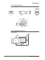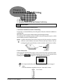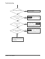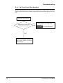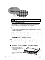
1
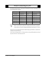
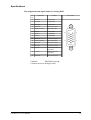
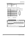
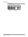
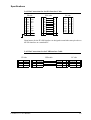
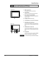
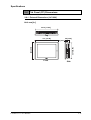
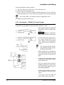
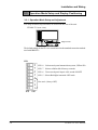
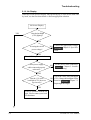
FP2600-T11 User Manual Digital Electronics Corporation Preface Thank you for purchasing Digital’s TFT type color display panel, the 'FP2600-T11' (hereafter referred to as the FP unit). The FP unit is a TFT type color liquid crystal display monitor for IBM-PC compatible personal computers (SVGA mode). Please read this manual completely to insure the correct use and complete understanding of the FP unit's functions. The FP's analog interface is designed for use with standard VGA mode. Please be aware that this unit may not be able to be connected with nonstandard VGA modes. For more details, please refer to this manual's "PC Connectivity Notes" section. The term FP2600-T11 refers to the following unit: FP2600-T11 (AC 100V type) <Note> 1) It is forbidden to copy the contents of this manual, in whole or in part, except for the user's personal use, without the express permission of the Digital Electronics Corporation of Japan. 2) The information provided in this manual is subject to change without notice. 3) This manual has been written with care and attention to detail; however, should you find any errors or omissions, please contact Digital Electronics and inform them of your findings. 4) Please be aware that Digital Electronics is not responsible for any damages resulting from the use of our products, regardless of article 3 above. 5) Specifications set out in this manual are for overseas products only, and, as a result, some differences may exist between the specfications given here and the Japanese ones. All Company/Manufacturer names used in this manual are the registered trademarks of their respective companies. © 2001, Digital Electronics Corporation FP2600-T11 User Manual i For the Safe And Correct Use of this Unit: This manual describes safety instructions for correct use of the FP unit. Please keep this manual close at hand, and refer to it when necessary. The following symbols are used throughout this manual to ensure the safe use of the FP unit. Please make sure to follow all instructions given since they explain important safety points. Warning This mark warns of a situation that could either seriously injure a person or lead to death if the instruction is ignored and/or the unit is used incorrectly. Caution This mark warns of a situation that could either injure a person or damage property if the instruction is ignored and/ or the unit is used incorrectly. Other Symbols Used In This Manual The list below describes the symbols used in this manual. Explains a situation that requires a moderate amount of caution. Indicates a word or phrase that has an additional explanation. *1 A reference point. Describes the word or phrase marked by the asterisk (*) and the corresponding number. Reference pages on related topics. 1),2) ii Operational steps. Please follow these numbered steps in order to perform the desired operation. FP2600-T11 User Manual Warning Safety Instructions For the safe use of this unit, be sure to follow these guidelines: Because of the ever present danger of electrical shock, be sure to unplug the power cable from the FP unit before plugging the cable's other end into the wall. Do not use power in excess of the unit's specified voltage range since it may cause a fire or electric shock. Because the FP unit contains high voltage parts, an electric shock can occur when disassembling the unit. Therefore, please be sure to always unplug the unit before disassembling it. Do not modify the FP unit in any way, since it may cause a fire or electric shock. When changing the backlight, be sure to turn off the unit's power first, in order to prevent an electric shock. Do not use touch panel keys to perform life-threatening or vitally important safety functions. Use separate mechanical switches for such keys. If substantial amounts of metallic dust, water or liquids enter the FP unit, turn off the power supply immediately, unplug the power cord, and contact your local FP distributor. When installing the FP unit, be sure to follow the instructions given in “Chapter 3. Installation and Wiring," to insure it is done correctly. Do not use the FP in an environment with flammable gas since it may cause an explosion. FP2600-T11 User Manual iii Caution Safety Instructions For the correct use of this unit, please follow these guidelines: Do not press the screen's touch surface too strongly with either your finger or a hard object, since the touch surface may be damaged. When the surface of the display screen becomes dirty or smudged, clean the display with a cloth soaked in a neutral detergent. Do not use paint thinner or organic solvent. Do not press on the touch panel's face with sharp objects, such as a mechanical pencil or screwdriver, since it might damage the LCD panel. Avoid using or storing the FP in direct sunlight, excessively dusty or dirty environments, or where chemicals or their vapors are present in the air. Avoid restricting the FP's natural ventilation, or storing and using the FP in an environment that will increase the FP's internal temperature. Please avoid using the FP in areas where sudden, large changes in temperature may occur. These changes can cause condensation to form inside the unit, possibly causing an accident. Notes on the FP's Liquid Crystal Display (LCD) The FP's LCD contains a strong irritant. If the panel is ever cracked and the LCD's liquid contacts your skin, be sure to wash it with running water for at least 15 minutes. If any of this liquid should enter your eye, be sure to flush the eye with running water for more than 15 minutes, and see a doctor immediately. The current brightness of the LCD screen will depend on the screen's current display and the LCD's contrast adjustment. Any brightness variations that result are normal for LCD displays. There are minute grid-points on the LCD surface. These points are not defects. Sometimes crosstalk (shadows appearing on extended display lines) will appear on the display. This phenomenon is a common attribute of LCD's and is not a defect. The displayed color will look different when viewed from an angle outside the specified view angle. This is also normal. Displaying a single screen image for long periods of time can cause an afterimage to remain. To correct this, turn the unit OFF for 5 or 10 minutes, then ON again. This phenomenon is a common attribute of the LCD's, and not a defect. To prevent this effect, you can: - use the Display OFF feature, if the same image is to be displayed for a long period of time. - change the screen display periodically to prevent the displaying of a single image for a long period of time. iv FP2600-T11 User Manual Table of Contents Preface ........................................................................................................................ i For the Safe and Correct Use of this Unit .................................................................. ii Warning: Safety Instructions ....................................................................................... iii Caution: Safety Instructions ........................................................................................ iv Table of Contents ........................................................................................................ v When Connecting to a PC ........................................................................................... vii FP2600-T11 Features .................................................................................................. viii Package Contents ....................................................................................................... ix Chapter 1—Introduction 1-1 Connecting the FP to a PC .................................................................................. 1-1 1-2 Optional Equipment ............................................................................................... 1-2 Chapter 2—Specifications 2-1 General Specifications (For AC100V) ............................................................................. 2-1 1 Electrical Specifications .............................................................................................. 2-1 2 Environmental Specifications ..................................................................................... 2-1 3 Structural Specifications ............................................................................................. 2-2 2-2 Functional Specifications (For AC100V) ......................................................................... 2-3 2-3 Interface Specifications (For AC100V) .......................................................................... 2-4 1 Analog RGB Interface ................................................................................................. 2-4 2 Serial Interface ............................................................................................................ 2-6 3 USB Interface .............................................................................................................. 2-7 2-4 Cable Diagrams ................................................................................................... 2-8 1 Pin Connections for the RGB Interface Cable ............................................................ 2-8 2 Pin Connections for the SIO Interface Cable ............................................................. 2-9 3 Pin Connections for the USB Interface Cable ........................................................... 2-9 2-5 Names and Functions of FP Parts .............................................................. 2-10 2-6 Flat Panel (FP) Dimensions ........................................................................ 2-11 1 External Dimensions (AC100V) ........................................................................... 2 Installation Brackets ........................................................................................... 3 FP Installation Dimensions ................................................................................. 2-11 2-12 2-12 Chapter 3—Installation and Wiring 3-1 Installation .......................................................................................................... 3-1 3-2 Wiring ................................................................................................................. 3-5 1 2 3 4 Power Cable Connection ............................................................................................ 3-5 Precautions: FP2600-T11 Power Supply ..................................................................... 3-6 Precautions: Grounding .............................................................................................. 3-7 Precautions: Input/Output Signal Lines .................................................................... 3-7 FP2600-T11 User Manual v 3-3 Operation Mode Setup and Display Positioning .......................................................3-8 1 Operation Mode Setup and Adjustment ..............................................................3-8 2 Front LED Option Mode Display ..................................................................................... 3-9 3 Display Position Compensation by OSD .......................................................................... 3-10 Chapter 4—Touch Panel Commands 4-1 Command List ..........................................................................................................4-1 4-2 Boot-up Initialization ................................................................................................4-2 4-3 Touch Interface Data ..............................................................................................4-3 4-4 Touch Panel Commands ..........................................................................................4-5 Chapter 5—Troubleshooting 5-1 Troubleshooting ........................................................................................................ 5-1 1 Possible Device Problems ................................................................................................ 5-1 2 No Display ........................................................................................................................ 5-2 3 Touch Panel Does Not Work ............................................................................................ 5-4 Chapter 6—Maintenance 6-1 Regular Cleaning ..................................................................................................... 6-1 1 Cleaning the Display ........................................................................................................ 6-1 2 Installation Gasket Check/Replacement ........................................................................... 6-1 6-2 Periodic Check Points ............................................................................................. 6-2 6-3 Replacing the Backlight ........................................................................................... 6-3 INDEX............................................................................................. i - iv vi FP2600-T11 User Manual When Connecting to a PC The FP unit's analog interface is designed for standard SVGA mode. The number of dots (pixels) displayed are as follows: Size 800 X 600 800 X 600 640 X 480 640 X 480 640 X 480 640 X 400 640 X 400 640 X 350 720 X 400 720 X 350 H Sync. 35.156±1 KHz 37.879±1 KHz 31.469±1 KHz 35.000±1 KHz 37.861±1 KHz 24.827±1 KHz 31.469±1 KHz 31.469±1 KHz 31.469±1 KHz 31.469±1 KHz V Sync. 56±1 Hz 60±1 Hz 60±1 Hz 66±1 Hz 72±1 Hz 56±1 Hz 70±1 Hz 70±1 Hz 70±1 Hz 70±1 Hz Dot Clock Range 36.000MHz±1% 40.000MHz±1% 25.175MHz±1% 30.240MHz±1% 31.500MHz±1% 21.053MHz±1% 25.175MHz±1% 25.175MHz±1% 28.322MHz±1% 28.322MHz±1% • With vertical 350 pixels, 400 pixels, including 50 pixels at the top and at the bottom of the screen will be enlarged and displayed at 600 pixels (1.5 times). Some types of VGA equipment may not be within the ranges specified above, and, therefore, cannot be connected to the FP. Also, if the user changes his PC's VGA board, there is the possiblity that the new board may not be able to be connected to the FP. FP2600-T11 User Manual vii FP2600-T11 Features The features of the FP2600-T11 are as follows. High Quality TFT Color LCD Display This unit is equipped with a 12.1 inch TFT type color LCD. Its superior brightness and wide viewing angle, not found in ordinary laptop type TFT LCD's, widens your scope of applications. The screen's maximum resolution is 800 x 600 pixels, and can display 260,000 colors. Easy Installation In User’s Cabinets and Panels The FP2600-T11's slim, lightweight, and compact design make installation a snap. It was designed specifically for use as your IA (Industrial Automation) or OA (Office Automation) system monitor. The flat, front panel provides protection equivalent to the rigorous IP65F standard, and, even without its optional protective cover, the front panel is highly resistant to both water and dust. Panel can be used as a VGA Display Since the FP2600-T11 is equipped with an analog RGB interface, it can be connected to any PC with standard VGA/SVGA mode. (The PC's clock frequency, however, must be within the standard range) Easy to use Built In Touch Panel The FP2600-T11's built in touch panel is standard equipment, allowing touch panel data to be output to a host PC via input/output commands and an RS-232C cable and USB cable. This is perfect for systems requiring both touch panel operation and data monitoring. viii FP2600-T11 User Manual Package Contents The FP's packing box contains the items listed below. Please check to be sure each is included and is not damaged. FP unit (FP2600-T11) FP2500/2600 User Manual (Contained in plastic case) User Manual Installation Gasket (1) Installation Brackets (4) FP2500-T11/FP2600-T11 Installation Guide (1) Installation Guide These items have all been carefully packed with special attention to product quality. However, should you find anything damaged or missing, please contact your local distributor immediately for prompt service. FP2600-T11 User Manual ix MEMO x FP2600-T11 User Manual Chapter 1 12345678901234567890123456789012 12345678901234567890123456789012 12345678901234567890123456789012 12345678901234567890123456789012 12345678901234567890123456789012 12345678901234567890123456789012 12345678901234567890123456789012 12345678901234567890123456789012 12345678901234567890123456789012 12345678901234567890123456789012 12345678901234567890123456789012 12345678901234567890123456789012 12345678901234567890123456789012 12345678901234567890123456789012 12345678901234567890123456789012 12345678901234567890123456789012 12345678901234567890123456789012 1. Connecting the FP to a PC 12345678901234567890123456789012 12345678901234567890123456789012 2. Optional Equipment 12345678901234567890123456789012 12345678901234567890123456789012 Introduction The following diagram illustrates the connection between the FP unit and a PC. 1-1 Connecting the FP to a PC FP2600-T11 unit 1 Analog RGB Interface Cable (FP-CV00<2.5m>,FP-CV01<5m>) (VGA standard: Dsub 15-pin male) B type 2 USB Interface Cable (5m) (FP-US00) (A-B type Cable) 1 2 3 3 SIO Interface Cable (5m) (FP61V-IS00-O) (Straight Cable: Dsub 9-pin female) A type Personal Computer (PC) FP2600-T11 User Manual 1-1 Introduction 1-2 Optional Equipment All optional items listed below are products of Digital Electronics Corporation. Item Interface SIO Cable FP61V-IS00-O RGB Cable FP-CV00 FP-CV01 USB Cable FP-US00 Backlight Bulbs Installation Maintenance Brackets Parts Rubber Gasket Optional Parts Model Description Serial interface cable (5m) used for touch panel data transmission between the host and the FP or command transmission to the FP. This is a straight Dsub9 pin female-cable. Analog RGB interface cable when image signal is output to the FP from the host. VGA specifications (Dsub15 pin male) FP-CV00 (2.5m), FP-CV01 (5m) USB interface cable (5m) used for touch panel data transmission between the host and the FP or command transmission to the FP. A-B type cable. PS600-BU00 Replacement Backlight bulbs . GP070-AT01 Metal installation brackets for FP2600-T11 GP-WP10-MS Cover Sheet (Hard type) PSL-DF00 Mouse Emulator V2 PL-TD000 Replacement rubber gasket, used when installing the FP. Same as the FP's original gasket. Provides disposable screen protection from dust and other elements. The touch panel can be used with the Cover Sheet attached (5 sheets / set) Mouse Emulator software for FP.* * Operation environment is Windows®95, WindowsNT®4.0, Windows®98, Windows®2000. When you use PL-TD000, hardware settings can not be automatically detected. As a result, select the FP unit's currently connected COM Port, and enter the settings given in the FP manual for the Allocated I/O address and Interrupt. 1-2 FP2600-T11 User Manual Chapter123456789012345678901234567890121 2 123456789012345678901234567890121 123456789012345678901234567890121 123456789012345678901234567890121 123456789012345678901234567890121 123456789012345678901234567890121 123456789012345678901234567890121 123456789012345678901234567890121 123456789012345678901234567890121 123456789012345678901234567890121 123456789012345678901234567890121 123456789012345678901234567890121 123456789012345678901234567890121 123456789012345678901234567890121 123456789012345678901234567890121 123456789012345678901234567890121 123456789012345678901234567890121 1. General Specifications 4. Cable Diagrams 123456789012345678901234567890121 123456789012345678901234567890121 123456789012345678901234567890121 2. Functional Specifications 5. Names and Functions of FP Parts 123456789012345678901234567890121 Specifications 3. Interface Specifications 6. Flat Panel (FP) Dimensions 2-1 General Specifications (For AC100V) 2-1-1 Electrical Specifications AC100V (FP2600-T11) Rated Voltage Power Consumption Allowable Voltage Drop Voltage Endurance Insulation Resistance AC 85V to AC 132V 50/60Hz 50VA or less 20ms or less AC1500V 20mA 1minute (between the live wire and grounding terminals) DC500V -above 10M Ω (between the live wire and grounding terminals) 2-1-2 Environment Specifications AC100V (FP2600-T11) Operating T emperature 0 oC to 50 o C Storage T emperature Humidity -10 oC to 60 oC 30 to 85%RH (non-condensing) Vibration Endurance Noise Immunity 19.8m/s2 - 10 to 25 Hz (X,Y,Z directions - 30 minutes each) Noise voltage: 1200 Vp-p Pulse length: 1 µs Rise time (rise/fall): 1 ns Not immune to corrosive gas Less than 100Ω, or your country's applicable standard Equivalent to IP65f (JEM1030) Pollution Level Grounding Protection*1 *1 (See the next page's note) FP2600-T11 User Manual 2-1 Specifications *1 (Continued from previous page) The front face of the FP unit, installed in a solid panel, has been tested using conditions equivalent to the standard shown in the specification . Even though the FP unit’s level of resistance is equivalent to the standard, oils that should have no effect on the FP can possibly harm the unit. This can occur in areas where either vaporized oils are present, or where low viscosity cutting oils are allowed to adhere to the unit for long periods of time. If the FP’s front face protection sheet becomes peeled off, these conditions can lead to the ingress of oil into the FP and separate protection measures are suggested. Also, if nonapproved oils are present, it may cause deformation or corrosion of the front panel’s plastic cover. Therefore, prior to installing the FP be sure to confirm the type of conditions that will be present in the FP’s operating environment. If the installation gasket is used for a long period of time, or if the unit and its gasket are removed from the panel, the original level of the protection cannot be guaranteed. To maintain the original protection level, you need to replace the installation gasket regularly. 2-1-3 Structural Specifications AC100V (FP2600-T11) External Dimensions Weight Cooling System 2-2 317W x 243H x 58D mm 3.5 kg or less Natural air circulation FP2600-T11 User Manual Specifications 2-2 Functional Specifications (For AC100 V ) Display Media Display Size Display Area (mm) Resolution Display Colors T FT Active matrix color LCD 31cm (type 12.1) Opposite angle 246.0W × 184.5H 800(H)×600(V)pixels(1pixel=R+G+B pixel) 262,144 colors (R/G/B Six bits each) Brightness 200cd/m 2 (typ)*1 0.33H×0.33W Resolution: 1024×1024 Method: Resistive Film (Analog) SVGA graphic & T ext mode 800×600,640×480,640×400,640×350,720×400,720 ×350 mode display available. However, with 350 pixels, 400 pixels, including 50 pixels at the top and bottom will be enlarged and displayed as 680 pixels (1.5 times). Dot Pitch (mm) T ouch Panel Display Mode Interfaces Backlight Analog RGB Interface SIO Interface(touch Interface) USB Interface(touch Interface) Backlight can be changed. Lifetime : 50,000 hours when continuously lit (*2) at 25o C. *1 The brightness at central part of the screen when displaying all white. *2 2.5 times decreased brightness may be the life span, but this value is only for reference and not a guaranteed value. FP2600-T11 User Manual 2-3 Specifications 2-3 Interface Specifications (For AC100V) 2-3-1 Analog RGB Interface Input signal type Analog RGB Input signal characteristic Image signal: analog RGB Synchronous signal: TTL level, negative true or positive true Scanning type: non-interlace Setting by OSD (On Screen Display) S iz e 800 x 600 800 x 600 640 x480 640 x 480 640 x 480 640 x 400 640 x 400 640 x 350 720 x 400 720 x 350 Contrast Adjustment Sub Contrast Adjustment Brightness Adjustment Horizontal Display Position Adjustment Vertical Display Position Adjustment Horizontal Adjustment Phase Adjustment Dimmer Adjustment Default Setting (All Clear Function) H S ync. 35.156± 1 37.879± 1 31.469± 1 35.000± 1 37.861± 1 24.827± 1 31.469± 1 31.469± 1 31.469± 1 31.469± 1 KHz KHz KHz KHz KHz KHz KHz KHz KHz KHz V S ync. 56± 1 60± 1 60± 1 66± 1 72± 1 56± 1 70± 1 70± 1 70± 1 70± 1 Hz Hz Hz Hz Hz Hz Hz Hz Hz Hz Dot Clock Ra nge 36.000M H z± 1% 40.000M H z± 1% 25.175M H z± 1% 30.240M H z± 1% 31.500M H z± 1% 21.053M H z± 1% 25.175M H z± 1% 25.175M H z± 1% 28.322M H z± 1% 28.322M H z± 1% • With vertical 350 pixels, 400 pixels, including 50 pixels at the top and at the bottom of the screen will be enlarged and displayed at 600 pixels (1.5 times). 2-4 FP2600-T11 User Manual Specifications Pin Assignments and Signal Names for Analog RGB Pin No. Signal Name Condition 1 Analog R R signal input 2 Analog G G signal input 3 Analog B B signal input 4 Reserved NC (spare for input) 5 Digital grounding Digital signal GND 6 Return R R signal GND 7 Return G G signal GND 8 Return B B signal GND 9 Reserved NC (spare for input) 10 Digital grounding Digital signal GND 11 Reserved NC (spare for input) 12 Reserved NC (spare for input) 13 H. SYNC Horizontal synchronous signal input 14 V. SYNC Vertical synchronous signal input 15 Reserved NC (spare for input) Pin Location 15 5 11 1 Connector: Mini Dsub 15 pin type Connector set screw: Inch type (4-40) FP2600-T11 User Manual 2-5 Specifications 2-3-2 Serial Interface Serial Interface Baud rate: 9600 bps Data length: 8 bits Parity: none Stop bit: 1 Pin Assignments and Signal Names for Serial Interface Pin No. Signal Name Condition 1 CD Carrier Detect (FP->Host) 2 RD Receive Data (FP->Host) 3 SD Send Data (FP<-Host) 4 DTR Data Terminal Ready (FP<-Host) 5 GND Ground 6 DSR Data Set Ready (FP->Host) 7 RS Request to Send (FP<-Host) 8 CS Clear to Send (FP->Host) 9 NC No connection Pin Location 6 9 1 5 Connector: Dsub 9 pin female Connector set screw: Inch type (4-40) Concerning Signal Names Signal names used for the serial interface on FP units are designed to match the pin order used on most PC serial interfaces, so that a straight cable can be used to connect the two. Therefore, connect each pin's signal to the same signal name on the PC side. For example, pin #2 'RD' should be connected to the 'RD' input terminal on the PC's connector. Refer to section "2-4 Cable Diagrams" for each signal's direction. 2-6 FP2600-T11 User Manual Specifications 2-3-3 USB Interface Pin Assignments and Signal Names for USB Interface Pin NO. 1 2 3 4 Signal Name USB1-5V USBD1(-) USBD1(+) GND Condition +5VIN USBdata(-) USBdata(+) Ground Communication Connector: FP2600-T11 User Manual Pin Location 1 2 3 4 Low speed Device B type connector 2-7 Specifications 2-4 Cable Diagrams 2-4-1 RGB Interface Cable Pin Connections FP side RGB cable 1 2 3 4 5 6 7 8 9 10 11 Analog R Analog G Analog B Reserved Digital ground Return R Return G Return B Reserved Digital ground Reserved Input Input Input --------- 12 Reserved 13 14 15 FG H.SYNC V.SYNC Reserved FG PC side 1 RED IN 2 GRIN IN 3 BLU IN 4 NC 5 GND 6 RED GND 7 GRN GND 8 BLU GND 9 NC 10 GND 11 NC RED VIDEO GRN VIDEO BLU VIDEO NC GROUND GROUND RED GROUND GRN GROUND BLU NC GROUND MONITOR SENSE(COLOR) 1 2 3 4 5 6 7 8 9 10 11 -- 12 NC MONITOR SENSE(MONO) 12 Input Input --- 13 14 15 FG HSYN VSYN NC FG HSYN VSYN NC FG Output RED VIDEO Output GRN VIDEO Output BLU VIDEO -NC -GROUND -GROUND RED -GROUND GRN -GROUND BLU -NC -GROUND -MONITOR SENSE(COLOR) --MONITOR SENSE(MONO) 13 Output 14 Output 15 -FG HSYN VSYN NC 1 2 3 4 5 6 7 8 9 10 11 12 13 14 15 Signal names for the FP's RGB interface are designed to match the same pin order as the RGB interface on personal computers. 2-8 FP2600-T11 User Manual Specifications 2-4-2 Pin Connections for the SIO Interface Cable FP side SIO cable PC side 1 CD Output 1 CD CD 1 Input CD 1 2 RD Output 2 RD RD 2 Input RD 2 3 SD Input 3 SD SD 3 Output SD 3 4 DTR Input 4 DTR DTR 4 Output DTR 4 5 GND -- 5 GND GND 5 6 DSR Output 6 DSR DSR 6 Input DSR 6 7 RS Input 7 RS RS 7 Output RS 7 8 CS Output 8 CS CS 8 Input CS 8 9 NC -- 9 NC RI 9 Input RI 9 FG FG -- FG FG FG 9 -- GND 5 Signal names for the FP's SIO interface are designed to match the same pin order as the SIO interface on a standard PC. 2-4-3 Pin Connections for the USB Interface Cable FP side 1 +5VIN 2 USB3 USB+ 4 GND Input Input/Output Input/Output Input/Output FP2600-T11 User Manual PC side USB cable 1 +5VIN 2 USB3 USB+ 4 GND Input 1 Input/Output Output +5VIN Input/Output USBInput/Output USB+ Input/Output Input/Output GND Input/Output 1 3 Output +5VIN Input/Output USBInput/Output USB+ 4 Input/Output GND 4 2 2 3 2-9 Specifications 2-5 Names and Functions of FP Parts Front View A: TFT Color LCD The display monitor for your host. B: Touch Panel Allows you to perform touch operation. H C: Power Input Terminal Block Provides the input and ground terminals for a power cable. D: Setting Switch (Dip switch) A,B E: VGA Interface (analog RGB) Connector F: Serial Interface Connector Used for both sending touch panel data to the host, and receiving commands from the host. Rear View G: USB Interface Connector Used for both sending touch panel data to the host, and receiving commands from the host. H: Front LED C D EF G An LED to detect power supply, backlight burning out and input of image signal. 3-3-2 Front LED Operation Mode Display 2-10 FP2600-T11 User Manual Specifications 2-6 Flat Panel (FP) Dimensions 2-6-1 External Dimensions ( AC100V ) Unit: mm [in.] 301.0 [11.85] Top 317 [12.48] 58 [2.28] 227.0 [8.94] 243 [9.57] 8 [0.31] Front FP2600-T11 User Manual Side 2-11 Specifications 2-6-2 Installation Brackets Unit: mm [in.] 11[0.43] 16[0.63] 31[1.22] 10[0.39] 19.5[0.77] 2-6-3 FP Installation Dimensions Unit: mm [in.] FP 2-12 R 2 227.5 +1 0 [8.96 +0.04 ] 0 Panel de +0.04 n 301.5 +1 [11.87 ] u 0 0 r4 FP2600-T11 User Manual C h a p t e12345678901234567890123456789012 r 3 12345678901234567890123456789012 12345678901234567890123456789012 12345678901234567890123456789012 12345678901234567890123456789012 12345678901234567890123456789012 12345678901234567890123456789012 12345678901234567890123456789012 12345678901234567890123456789012 12345678901234567890123456789012 12345678901234567890123456789012 12345678901234567890123456789012 12345678901234567890123456789012 12345678901234567890123456789012 12345678901234567890123456789012 12345678901234567890123456789012 12345678901234567890123456789012 12345678901234567890123456789012 1. Installation 12345678901234567890123456789012 12345678901234567890123456789012 12345678901234567890123456789012 2. Wiring Installation and Wiring 3. Operation Mode Setup and Display Positioning 3-1 Installation Install the FP unit using the following steps. Confirm the Installation Gasket's Positioning It is strongly recommended that you use the gasket. It absorbs vibration in addition to repelling water. Place the FP on a level surface with the display panel facing downward. Check that the FP's installation gasket is seated securely into the gasket's groove, which runs around the perimeter of the panel's frame. A gasket which has been used for a long period of time may have scratches or dirt on it, and could have lost much of its dust and drip resistance. Be sure to change the gasket periodically (or when scratches or dirt become visible). Rear View Gasket Create a Panel Cut Following the FP Installation dimensions, create (cut) the FP opening required for installation. The FP's rubber gasket, installation brackets and screws are all required when installing the FP. Chapter 2-6-3 "FP Installation Dimensions". Panel Panel Cut • It is important that the panel surface is flat, clean, and has no jagged edges. • The Panel thickness should be between 1.6mm and 10.0mm. 1.6 to 10mm FP2600-T11 User Manual 3-1 Installation and Wiring • For easier maintenance and operation, and improved ventilation, be sure the FP unit is mounted at least 100 mm away from any adjacent structures or objects. • The FP uses natural ventilation through its outer shell for cooling. When installing the unit horizontally or sideways (portrait style), use a fan or air conditioning unit to prevent overheating. Vertical Installation Side Front Horizontal Installation Sideways Installation • When installing the FP sideways, place it so that the Power Terminals point upwards. • Check that heat from surrounding equipment will not cause the FP to overheat. • Do not use the FP2600-T11 in an environment that exceeds 50o C. • Ensure this unit is located as far away as possible from electromagnetic circuits, non-fuse type breakers, and other equipment that can cause arcing. • When installing the FP unit in a panel with an angled face, the face should not incline either backwards or forwards more than 30o. less than 30o 3-2 FP2600-T11 User Manual Installation and Wiring Installing the FP Panel 1) Insert the FP into the panel cut out, as shown here. FP Insertion Slots Top 2) Insert the installation fasteners into the FP’s insertion slots, at the top and bottom of the unit. (total: 4 slots) Insertion Slots Bottom 3) Insert each of the fasteners shown below. Be sure to pull the fastener back until it is flush with the rear of the attachment hole. FP2600-T11 User Manual 3-3 Installation and Wiring 4) Use a Phillips screw driver to tighten each fastener screw and secure the FP in place. Do not use too much force, since it may damage the FP unit. A torque of only 0.5 N•m is sufficient to tighten these screws. 3-4 FP2600-T11 User Manual Installation and Wiring 3-2 Wiring 3-2-1 Power Cable Connection Warning • To prevent electrical shocks, be sure the Power Cable is plugged first into the FP unit, then into the wall (main supply). • Your FP2600-T11 uses input voltage of only AC100V. If your power supply is greater than that required by your unit, it may damage both the power source and the FP unit. • In lieu of the power switch on the FP unit, please connect a breaker unit. • When connecting the FG terminal, be sure to connect the ground wire. Not grounding the FP unit will create excessive noise and vibration. Wherever possible, use thick wires (max. 2mm2) for power terminals, and provide an extra twist to the wire before connecting it. The ring terminal size should be as follows. 3.2 mm • • less than 6.0 mm • To avoid a power short when loosening power terminal screws, use a power terminal with plastic sleeves. FP2600-T11 (Rear) 100V Unit FP2600-T11 L L N N FG FG *1 Power Terminal Block Crimp-on Ring Terminals *1 The three power terminals are: AC100V L = AC Input Terminal—live line AC100V N = AC Input Terminal—neutral line FG = Ground Terminal connected to the FP chassis FP2600-T11 User Manual 3-5 Installation and Wiring Connect the FP power cable as follows: 1) Check to make sure the FP's power cord is disconnected. 2) Remove the plastic terminal cover. 3) Remove the screws from the 3 middle terminals, align the power wire connectors and re-insert the screws. (Check each wire to make sure it is securely connected) Use no more than 0.5 to 0.6N•m of torque to tighten the screws. 4) Replace the plastic terminal cover. 3-2-2 Precautions: FP2600-T11 Power Supply Please pay special attention to the following points when connecting the power cable to the Power Terminal Block at the back of the FP2600-T11 unit. • constant voltage transformer Twisted Lines FP unit If the supplied voltage exceeds the FP unit's range, connect a voltage transformer. Chapter 2, "Specifications", for the allowable voltage range. Twisted Lines isolating transformer main power FP unit • FP power Use Voltage and Noise Reducing transformers that have capacities that exceed 100VA. FP unit input/output unit main power • When supplying power to the FP unit, please separate the input/output and operation unit lines as shown in the figure. • To increase the noise quality, simply twist the power cable before connecting it to the FP unit. • The power supply cable must not be bundled or kept close to main circuit lines (high voltage, high current), or input/output signal lines. • Connect a surge absorber, as shown in the diagram, to deal with power surges. • To avoid excess noise, make the power cable as short as possible. FP power FP unit Input/ Output Power power input/output Input/ Output Power main circuit Operation Unit 3-6 For between the line and ground, select a power supply that is low in noise. If there is an excess amount of noise, connect a noise reducing transformer. FP2600-T11 User Manual Installation and Wiring FP unit surge absorber • Make sure the surge absorber (E1) is grounded separately from the FP unit (E2). • Select a surge absorber that has a maximum circuit voltage greater than that of the peak voltage of the power supply. 3-2-3 Precautions: Grounding (a) Exclusive grounding (BEST) FP unit other equipment Connect the FP's FG terminal to an exclusive ground. [diagram (a) Grounding resistance of under 100Ω.] If exclusive grounding is not possible, use a common connection point. [diagram (b)] (b) Common grounding (OK) FP unit other equipment (c) Common grounding (BAD) FP unit other equipment The grounding wire should have a cross sectional area greater than 2mm2. Make the connection point as close to the FP unit as possible, and make the wire as short as possible. When using a long grounding wire, replace the thin wire with a thicker wire placed in a duct. If this equipment does not function properly when grounded, disconnect the ground wire from the FG terminal. 3-2-4 Precautions: Input/Output Signal Lines Input and output signal lines must be separated from operating circuit power cables. If this is not possible, use a shielded cable and connect the shield to the FP chassis. FP2600-T11 User Manual 3-7 Installation and Wiring 3-3 Operation Mode Setup and Display Positioning 3-3-1 Operation Mode Setup and Adjustment The setup switches (dip-switches) are located in the rear of the unit. FP2600-T11 (rear view) Dip-switch The default settings for the FP were created based on the standard connection method used with IBM-PCs. SW1 SW1-8 Selects touch panel transmission system, USB or SIO SW1-7 Selects valid/invalid of factory set mode SW1-6 Turns touch panel input's click sound ON/OFF SW1-5 Selects Backlight Automatic OFF mode Not used (Always OFF) 3-8 FP2600-T11 User Manual Installation and Wiring SW1-5 This switch controls the Automatic Backlight OFF mode. When this switch is ON, and if there is no SIO transmission or touch operation performed for 5 minutes, the backlight turns off automatically. It will remain OFF until another SIO transmission or touch operation takes place, at which time the backlight automatically turns back on. If the FP unit is frequently not used, please set this switch ON to extend the life of the backlight. Also, if a display related command is transmitted by the SIO, this Automatic Backlight OFF mode will be automatically disabled. SW1-6 This controls is used as the touch screen Click sound's ON/OFF switch. When this is set to ON, a click will sound every time the touch panel is touched. SW1-7 This is a switch to shift as adjustment mode at factory. Please set this switch OFF when the FP unit is used. SW1-8 This is a switch to change the data input (command control) of the touch panel. Data output and command input/output will be performed from the USB connector when this is ON and from the RS232C connector when it is OFF. 3-3-2 Front LED Operation Mode Display L ED Co n d itio n P a ne l L ig h t O F F G re e n Pow er O F F Pow er O N N orm al Yes Ba cklig h t Im a g e in p u t FP2600-T11 User Manual O ra n g e lig h tin g Pow er O N N orm al No G re e n /Re d b lin kin g Pow er O N Bulb burned out Yes O ra n g e b lin kin g Pow er O N Bulb burned out No 3-9 Installation and Wiring 3-3-3 Display Position Compensation by OSD The OSD (On Screen Display) is the screen menu displayed on the central part of the screen when the following FP startup is performed. 1) OSD Startup Method 1) 2) Touch the screen within 5 seconds in order of 1) , 2) and 3). Display 3) 2) Main Menu The left illustrations are the main menu of OSD. P CL 3-10 D By touching the characters on the display screen, you can switch to that screen adjustment mode. Touching the ESC key will exit OSD mode. ESC FP2600-T11 User Manual Installation and Wiring 3) Characters and their functions Contrast adjustment : The function to adjust Contrast Sub-contrast adjustment : The function to adjust contrast of each RGB color. Brightness adjustment : The function to adjust brightness of colors. Horizontal display position adjustment : The function to adjust horizontal position of the display screen. Vertical display position adjustment : The function to adjust the vertical position of the display screen. Horizontal size adjustment : The function to adjust the horizontal size of the screen. P Phase adjustment : The function to compensate the flicker. D Dimmer function : The function to compensate the flicker of backlight. CL Setup value clear : Returns all setup values to default values. ESC Closes the OSD. SET Saves the setup values. FP2600-T11 User Manual 3-11 Installation and Wiring 4) Menu Settings <Example> Contrast Adjustment Ajustment item Adjustment bar Adjustment key SET ESC Save setup values Cancel The value for each setting item can be increased or decreased by pushing the adjustment key. • Contrast, Sub Contrast : Higher contrast can be obtained by the value +. • Brightness : A hue can be brightened by the value +. • Horizontal Display Position Adjustment : Display moves right by pressing the value +. • Vertical Display Position Adjustment : Display moves up by pressing the value +. • Horizontal Size Adjustment : Screen size can be enlarged horizontally by the value +. • Phase Adjustment : CLK phase can be slowed by the value +. • Dimmer Adjustment : Backlight can be brightened by the value +. Push the SET key to save the setup value. Pushing the ESC key will return you to the main menu. Clearing the Setup Value ALLCLEAR START ESC 3-12 Push the character CL and it will shift to this screen. When you push START, all setup data of the adjustment items will be returned to default value (factory set up value). By pushing the ESC key, you will return to the main menu. FP2600-T11 User Manual Chapter 4 12345678901234567890123456789012 12345678901234567890123456789012 Touch 12345678901234567890123456789012 Panel Commands 12345678901234567890123456789012 12345678901234567890123456789012 12345678901234567890123456789012 12345678901234567890123456789012 12345678901234567890123456789012 12345678901234567890123456789012 12345678901234567890123456789012 12345678901234567890123456789012 12345678901234567890123456789012 12345678901234567890123456789012 12345678901234567890123456789012 12345678901234567890123456789012 1. Command List 3. Touch Interface Data 12345678901234567890123456789012 12345678901234567890123456789012 2. Boot-up Initialization 4. Touch Panel Commands 12345678901234567890123456789012 12345678901234567890123456789012 12345678901234567890123456789012 12345678901234567890123456789012 4-1 Command List Here, the touch panel commands ( host -> touch panel ) supported by the FP2600T11 are described. The comma (,) used between the transferred format sent by the touch panel to the host computer is only for separating commands, and has nothing to do with the actual touch panel commands. Command codes and data are all expressed in hexadecimal format. (Example: 65h = 65 HEX) <Touch Panel Commands> Regardless of the dip-switch settings, the FP's display, click sound and buzzer can all be controlled from the host computer by sending one-character touch panel commands to the FP unit. The dip-switch settings are only enabled when the FP is turned ON. Code 65h / 67h 66h / 68h 69h 6Ah 6Bh 6Ch 71h 72h 73h 74h FP2600-T11 User Manual Function Display ON Display OFF Click sound (high) ON Click sound (high) OFF Click sound (low) ON Click sound (low) OFF Buzzer (high) ON Buzzer (high) OFF Buzzer (low) ON Buzzer (low) OFF 4-1 Touch Panel Commands 4-2 Boot-up Initialization When the power is turned ON, the touch panel is initialized as follows. Clears its internal buffer. Initializes the serial communication mode. Baud rate 9600bps Data length 8 bits Parity none Stop bit 1 bit Initializes the system default values. 4-2 Function Default Setting Display output ON Backlight ON Click sound ON or OFF selected with Dip SW1-6 (high) Buzzer OFF Automatic OFF mode ON or OFF selected with Dip SW1-5 FP2600-T11 User Manual Touch Panel Commands 4-3 Touch Interface Data Since the FP uses an analog type touch panel, all 800 x 600 coordinates can be detected. Resolution of the analog touch panel is 1024 x 1024, so a conversion program to convert the coordinates to 800 x 600 becomes necessary. Also, a calibration program to adjust the actual touch position is needed. As a result, the following software is included with the FP2600-T11 unit. OS and Touch Panel Driver Combinations OS Windows (R) NT Touch I/F Program PL-TD000 Windows (R) 95 PL-TD000 Windows (R) 98 PL-TD000 Windows (R) 2000 PL-TD000 Others user programmed Calibration Feature included in the touch I/F program Feature included in the touch I/F program Feature included in the touch I/F program Feature included in the touch I/F program user programme Touch Panel Coordinate Data (1) Resolution Both the X and Y coordinates have a resolution of 1024. The origin point (0,0) is located in the upper left corner of the screen. (0,0) Screen display origin, with resolution of 800 x 600, is normally at the upper left corner of the screen. Therefore, a software to convert the touch coordinates to display coordinates is needed. (1023,1023) FP2600-T11 User Manual 4-3 Touch Panel Commands (2) Data Format All data is in binary format. Header: X coordinate: Y coordinate: 1 byte (11h= touched; 10h = released) 2 bytes (0 to 3FFh) 2 bytes (0 to 3FFh) X coordinate Y coordinate 10h 11h Added when touch is released. <Example> If the coordinate (X=23(11h), Y=500(1F4h)) is touched. 11h 0h 17h 1h F4h 11h 0h 17h 1h F4h 11h 0h 17h 1h F4h 11h 0h 17h 1h F4h touched continuous output with the same location moving the location without releasing touch continuous data output unless finger is released 11h 0h 17h 1h F4h 11h 0h 17h 1h F4h 10h when released, only 1 unit of data is sent (3) Sampling Rate A maximum of 87 points per second. 4-4 FP2600-T11 User Manual Touch Panel Commands 4-4 Touch Panel Commands The following are touch panel commands sent from the host computer to the FP unit. The letter inside the bracket next to the command code shows the actual character used for that code. Display ON 65h ( e ) / 67h ( g ) RS232C 65h ( e ) / 67h ( g ) USB Turns on FP2600-T11's display. Backlight is also turned on simultaneously. Display OFF 66h ( f ) / 68h ( h ) RS232C Display OFF 66h ( f ) / 68h ( h ) USB Turns off FP2600-T11's display. Backlight is also turned off simultaneously. • When the display is turned off by using this command, it is necessary to write the Display ON command to turn it on again. • Unlike when making the display turn off by automatic backlight OFF mode, the display will not reappear by touching the panel. Further, the Automatic Backlight OFF mode is set up by the Dip Swtch 1-5 and the mode will be decided by the Dip Switch setup condition when the power source of the FP unit is turned on. Click sound (high) ON 69h ( i ) RS232C 69h ( i ) USB Makes a high click sound when the touch panel is touched. Click sound (high) OFF 6Ah ( j ) RS232C 6Ah ( j ) USB The high click sound is disabled. Click sound (low) ON 6Bh ( k ) RS232C 6Bh ( k ) USB Makes a low click sound when the touch panel is touched. Click sound (low) OFF 6Ch ( l ) RS232C 6Ch ( l ) USB The low click sound is disabled. FP2600-T11 User Manual 4-5 Touch Panel Commands Buzzer (high) ON 71h ( q ) RS232C Buzzer (high) ON 71h ( q ) USB Turns on the buzzer output (high). Buzzer (high) OFF 72h ( r ) RS232C Buzzer (high) OFF 72h ( r ) USB Turns off the buzzer output (high). Buzzer (low) ON 73h ( s ) RS232C 73h ( s ) USB Turns on the buzzer output (low). Buzzer (low) OFF 74h ( t ) RS232C 74h ( t ) USB Turns off the buzzer output (low). The order of priority for the buzzer and click sounds is as follows. They are not processed simultaneously. Sound Command Code Buzzer (high) ON 71h Buzzer (low) ON 73h Click sound (high) ON 69h Click sound (low) ON 6Bh Priority Order high low Also, if the OFF command for each buzzer item is sent, regardless of the priority order, only that buzzer item is turned off. <Example> If the following three commands are sent at the same time... Buzzer (high) ON Buzzer (low) ON ... the Buzzer (high) activates. However, when the Buzzer (high) OFF command is sent afterwards, the Buzzer (low) will activate. 4-6 FP2600-T11 User Manual Touch Panel Commands Reserved The following commands are reserved. If these commands are used, they are sometimes treated as errors. 00h 01h 02h 05h 0Ah 0Bh 0Dh 0Eh 0Fh 14h 15h 16h 17h 18h 19h 1Bh 1Dh 20h 21h 22h 23h 25h 26h 27h 28h 29h 2Ah 2Bh 31h 33h 3Ah 3Ch 41h 42h 43h 44h 45h 46h 47h 55h FP2600-T11 User Manual Reserved 4-7 Touch Panel Commands MEMO 4-8 FP2600-T11 User Manual Chapter12345678901234567890123456789012 5 12345678901234567890123456789012 12345678901234567890123456789012 12345678901234567890123456789012 12345678901234567890123456789012 12345678901234567890123456789012 12345678901234567890123456789012 12345678901234567890123456789012 12345678901234567890123456789012 12345678901234567890123456789012 12345678901234567890123456789012 12345678901234567890123456789012 12345678901234567890123456789012 12345678901234567890123456789012 12345678901234567890123456789012 12345678901234567890123456789012 Troubleshooting 12345678901234567890123456789012 12345678901234567890123456789012 12345678901234567890123456789012 12345678901234567890123456789012 12345678901234567890123456789012 Troubleshooting 1. 5-1 Troubleshooting 5-1-1 Possible Device Problems Possible types of trouble while using this unit are as follows. No display - No display appears after the unit is switched on. - The screen disappears during running mode. - The screen does not display normally. Touch panel doesn't function The touch panel does not react when pressed, or its reaction time is abnormally long. Warning - Because of the danger of electric shocks, be sure the power cable is not connected when wiring the unit. - When changing the backlight, there is a danger of electric shocks or burns, so be sure to turn the unit OFF and wear gloves. This section assumes that the FP is the cause of a problem, not the host. When the host is the problem, please refer to its corresponding manual. FP2600-T11 User Manual 5-1 Troubleshooting 5-1-2 No Display When the screen does not display when powering up, or if the screen turns OFF by itself, use the flowchart below to find an appropriate solution. No Screen Display YES Does the backlight (CFL) light up? NO Is it using the correct power voltage? NO Connect the appropriate voltage. Chapter 2. Specifications. NO Fix the power cable connection. Chapter 3. Installation and Wiring. YES Turn OFF the power switch. Is the power supply cable connected properly to the unit? YES Has the 11V unit's backlight (CFL) been set up correctly? Check the 100V unit's backlight NO (CFL). Change the backlight if it has burnt out. Chapter 7-3 Replacing the Backlight. YES There is a problem with the FP unit. Please contact your local FP distributor. 5-2 FP2600-T11 User Manual Troubleshooting Is the computer operating? NO Start the computer. YES Is RGB cable connected NO correctly? Connect the RGB cable correctly. Chapter 2-4 Cable Diagrams. YES Is display mode NO right? Select the correct display mode with Dip SW1-4. Chapter 3-3 Operation Mode Setup and Display Positioning. YES Does the screen display correctly? YES Adjust the screen display position. Chapter 3-3 Operation Mode Setup and Display Positioning. NO There is a problem with the FP unit. Please contact your local FP distributor. FP2600-T11 User Manual 5-3 Troubleshooting 5-1-3 The Touch Panel Does Not Work When the touch panel does not react, or its reaction is very slow after it is pressed, follow the flowchart below to find the origin of the problem and the appropriate solution. Touch panel not working Is the SIO or USB cable connected correctly? NO Connect the SIO or USB cable correctly. 2-4 Cable Diagrams YES There is a problem with the FP unit. Please contact your local FP distributor. 5-4 FP2600-T11 User Manual Chapter 12345678901234567890123456789012 6 12345678901234567890123456789012 12345678901234567890123456789012 12345678901234567890123456789012 12345678901234567890123456789012 12345678901234567890123456789012 12345678901234567890123456789012 12345678901234567890123456789012 12345678901234567890123456789012 12345678901234567890123456789012 12345678901234567890123456789012 12345678901234567890123456789012 12345678901234567890123456789012 12345678901234567890123456789012 12345678901234567890123456789012 12345678901234567890123456789012 1. Regular Cleaning 12345678901234567890123456789012 12345678901234567890123456789012 12345678901234567890123456789012 2. Periodic Check Points 12345678901234567890123456789012 12345678901234567890123456789012 Maintenance 3. Changing the Backlight 6-1 6-1-1 Regular Cleaning Cleaning the Display When the surface or the frame of the display gets dirty, soak a soft cloth in water with a neutral detergent, wring the cloth tightly, and wipe the display. • Do not use paint thinner, organic solvents, or a strong acid compound to clean the unit. • Do not use hard or pointed objects to operate the touch-screen panel, since it can damage the panel surface. 6-1-2 Installation Gasket Check/Replacement The installation gasket protects the FP and improves its water resistance. For instructions on installing the FP's gasket, refer to Chapter 3 "Installation and wiring" A gasket which has been used for a long period of time may have scratches or dirt on it, and could have lost much of its water resistance. Be sure to change the gasket at least once a year, or when scratches or dirt become visible. Installation Gasket Attachment Procedure (all units) 1) Place the FP on a flat, level surface facing the display face downwards. 2) Remove the gasket from the FP. FP2600-T11 User Manual 6-1 Maintenance 3) Attach the new gasket to the FP. Be sure to insert the gasket into the GP’s groove so that the gasket’s groove sides are vertical. 4) Check if the gasket is attached to the FP correctly. • The gasket must be inserted correctly into the groove for the FP’s moisture resistance to be equivalent to IP65f. • The upper surface of the gasket should protrude approximately 2mm out from the groove. Be sure to check that the gasket is correctly inserted before installing the FP into a panel. Unit: mm [in.] 2.0 [0.08] 6-2 Periodic Check Points To keep your FP unit in its best condition, please inspect the following points periodically. FP Operation Environment • Is the operating temperature within the allowable range (0oC to 50oC )? • Is the operating humidity within the specified range (30%RH to 85%RH, dry bulb temperature of 39oC or less)? • Is the operating atmosphere free of corrosive gasses? Electrical Specifications • Is the input voltage appropriate (AC85V to AC132V)? Related Items • Are all power cords and cables connected properly? Have any become loose? • Are all mounting brackets holding the unit securely? • Are there many scratches or traces of dirt on the installation gasket? 6-2 FP2600-T11 User Manual Maintenance 6-3 Replacing the Backlight When the unit’s backlight burns out, the unit’s status LED will brink green/red or orange. FP2600-T11 units use a CFL, long-life type backlight. The actual life of the backlight however, will vary depending on the FP’s operating conditions, and replacement may be required. A FP2600-T11 backlight has a life of 50,000 hours (approx. 5.7 years, at 25oC and 24 hour operation), when the backlight is lit continuously (time required for brightness to fall to half its normal level.) Warning • To prevent an electric shock, be sure the FP’s power cord is un plugged from the power outlet prior to replacing the backlight. • When the power has just been turned OFF, the unit and backlight are still very hot. Be sure to use gloves to prevent burns. • The backlight is very fragile. Do not touch the glass tube directly or try to remove its power cord. If the glass tube breaks you may be injured. Use the following table to check that you have ordered the correct backlight. FP Model FP2500-T11 FP2600-T11 Backlight Model GP577R-BL00-MS PS600-BU00 For backlight replacement details, refer to the replacement backlight unit’s installation guide. FP2600-T11 User Manual 6-3 Maintenance MEMO 6-4 FP2600-T11 User Manual Index A Afterimage iv Analog RGB interface viii, 2-4, 2-8, 2-10 Analog RGB Interface Cable 1-1, 1-2, 2-8 Angled face 3-2 Automatic OFF Mode 3-8, 3-9, 4-5 B Backlight 1-2, 2-3, 6-3 Boot-up Initialization 4-2 Brightness 2-3 Brightness adjustment 3-11, 3-12 Buzzer 4-1, 4-6 C Cable Diagrams 2-8 Cleaning the Display 6-1 Click sound 3-8, 3-9, 4-1, 4-6 Command List 4-1 Common grounding 3-7 Connecting the FP to a PC 1-1 Contrast adjustment 3-11, 3-12 Cover sheet 1-2 Clearing the Setup Value 3-12 E Electrical Specifications 2-1, 6-2 Environmental Specifications 2-1 Exclusive grounding 3-7 External Dimensions 2-2, 2-11 F Factory Set Mode 3-8, 3-9 FG terminal 3-5, 3-7 Flammable gas (environment) iii Flat Panel (FP) Dimensions 2-11 FP Installation Dimensions 2-12 FP Operation Environment 6-2 FP Parts Names and functions 2-10 Front LED 2-10, 3-9 Functional Specifications 2-3 G General Specifications 2-1 Grounding 3-7 Ground Connection 2-1 Guidelines iii H D Data Format binaly format 4-4 Dimmer function 3-11, 3-12 Dip switch 2-10, 3-8 Disassembling iii Display Area 2-3 Display colors 2-3 Display Media 2-3 Display mode vii, 2-3 Display Position Compensation by OSD 3-10 Dot Pitch 2-3 FP2600-T11 User Manual Header Data Format 4-4 High voltage iii Horizontal Installation 3-2 Horizontal size adjustment 3-11, 3-12 Horizontal display position adjustment 3-11, 3-12 I IA (Industrial Automation) viii Input Voltage 2-1, 3-5 Insertion Slot 3-3 Installation 3-1 Installation Gasket ix, 3-1, 6-1 Installation Guide ix Installation brackets ix, 1-2, 2-12, 3-3 Interface Specifications 2-4 Internal buffer 4-2 IP65F 2-1 i L S Liquid Crystal Display (LCD) iv Safety Instructions iii, iv Sampling Rate 4-4 Serial Interface 2-6, 2-10 Setup value clear 3-11, 3-12 Sideways Installation 3-2 Signal Names 2-5, 2-6, 2-7 SIO Interface Cable 1-1, 1-2, 2-9 Specifications Electrical 2-1 Environmental 2-1 Interface 2-4 Structural 2-2 Storage Temperature 2-1 Structural Specifications 2-2 Sub-contrast adjustment 3-11, 3-12 Surge absorber 3-7 Symbols ii M Maintenance 6-1 Maintenance parts 1-2 Metallic dust iii Mouse Emulator 1-2 N Natural ventilation iv, 3-2 Noise Endurance 2-1 No Screen Display Troubleshooting 5-2 O OA (Office Automation) viii Operating Temperature 2-1 Operation Mode Setup 3-8 Optional Equipment 1-2 Overheat 3-2 OSD 2-4, 3-10 P Packaging Contents ix Phase adjustment 3-11, 3-12 Pin Assignments 2-5, 2-6, 2-7 PL-TD000 1-2, 4-3 Possible Device Problems 5-1 Power Cable Connection 3-5 Power Input Terminal Block 2-10, 3-5 Power Terminals 3-5 Precautions: Grounding 3-7 Precautions: Input/Output Signal Lines 3-7 Precautions: Power Supply 3-6 Priority Buzzer and Click sounds 4-6 T TFT Color LCD viii, 2-10 Touch Interface Data 4-3 Touch Panel 2-3, 2-10 Touch Panel Command 4-1, 4-5 Touch Panel Coordinate Data 4-3 Touch Panel Does Not Work Troubleshooting 5-4 Touch Panel Driver 4-3 Troubleshooting 5-1 U User Manual ix USB Interface 2-7, 2-10 USB Interface Cable 1-1, 1-2, 2-9 V Vertical Installation 3-2 Vertical display adjustment 3-11, 3-12 Vibration Endurance 2-1 Voltage Transformer 3-6 R Rubber gasket 1-2, 3-1 W Weight 2-2 Wiring 3-5 Grounding 3-7 Input/Output Signal Lines 3-7 Power Cable 3-5 Power Supply 3-6 When Connecting to a PC vii ii FP2600-T11 User Manual