1
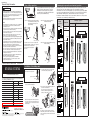
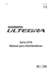
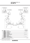
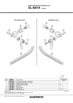
SHIMANO 105 Dual Control Lever (For Triple Gear)
ST-5703-S
ST-5703-L
Silver Version
Black Version
For Left Hand
7
8
6
1
9
2
10
12
11
3
TOOL
14
4
13
ITEM
NO.
1
2
3
4
5
6
7
8
9
10
11
12
13
14
SHIMANO
CODE NO.
Y6TK98010
Y6TK98020
Y6TH98060
Y6TJ52000
Y6RU87010
Y6SC98070
Y6TK98030
Y6SC98150
Y6SE14000
Y6TK98040
Y6SE98040
Y6SC76010
Y6SC75010
Y6TK09000
Y6RT68000
Y6RT66000
DESCRIPTION
L.H. Main Lever Assembly (Silver)
L.H. Main Lever Assembly (Black)
L.H. Name Plate & Fixing Screws
L.H. Main Lever Support
L.H. Release Lever Support
Lever Axle & E-ring
L.H. Bracket Unit
Clamp Band Unit (ø23.8 mm - ø24.2 mm)
L.H. SL Cable Guide
L.H. Bracket
Unit Cover & Fixing Screw
L.H. Adjustment Block (5 mm)
L.H. Adjustment Block (10 mm)
Bracket Cover
Tool A for E-ring
Tool B for E-ring
A: Same parts.
B: Parts are usable, but differ in materirals, appearance, finish, size, etc.
Absence of mark indicates non-interchangeability.
Specifications are subject to change without notice.
ST
-57
03
ST
-67
03
(fo
r
Le
ft)
5
INTERCHANGEABILITY
A
A
A
A
A
A
A
A
A
A
A
A
A
A
A
Mar.-2010-3029
© Shimano Inc. I
SI-6SE0B-002-00
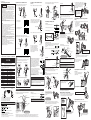
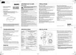
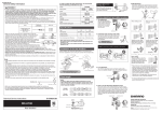
General Safety Information
Gear shifting operations
Lever (b) will also move when lever (a) is operated,
but be careful not to apply pressure to lever (b).
Similarly be careful not to press lever (a) when
operating lever (b). Gears will not shift when both
levers are pressed simultaneously.
WARNING
• Obtain and read the service instructions carefully prior to
installing the parts. Loose, worn or damaged parts may cause
the bicycle to fall over and serious injury may occur as a result.
We strongly recommend only using genuine Shimano
replacement parts.
• Read these Technical Service Instructions carefully, and keep
them in a safe place for later reference.
Note
• The ST-6703/5703 front dual control lever is for use with triple
front chainwheels, and cannot be used with double front
chainwheel products.
• Operation of the levers related to gear shifting should be made
only when the front chainwheel is turning.
• For smooth operation, use the specified outer casing and the
bottom bracket cable guide.
• Grease the inner cable and the inside of the outer casing
before use to ensure that they slide properly.
• Use a frame with internal cable routing is strongly discouraged
as it has tendencies to impair the SIS shifting function due to
its high cable resistance.
• A special grease is used for the gear shifting cable. Do not use
DURA-ACE grease or other types of grease, otherwise they
may cause deterioration in gear shifting performance.
• Please refer to the Service Instructions for the ST-6700/5700
for details on installation and maintenance.
• Be sure to read these service instructions in conjunction with
the service instructions for the FD-6703/5703 before use.
• Parts are not guaranteed against natural wear or deterioration
resulting from normal use.
• For maximum performance we highly recommend Shimano
lubricants and maintenance products.
• For any questions regarding methods of installation,
adjustment, maintenance or operation, please contact a
professional bicycle dealer.
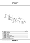
Trimming (noise prevention mechanism) operation
Lever (b)
Lever (a)
• Lever a : Shifting from the smallest chainring
to the intermediate chainring or from
the intermediate chainring to the
largest chainring
• Lever b : Shifts from largest chainring to
intermediate chainring.
Depending on the position of the chain after shifting, the chain may rub against the chain
guide outer plate or the chain guide inner plate of the front derailleur, producing a
characteristic noise. If this sort of thing happens, you can press lever (a) or lever (b) slightly
to move the front derailleur a little way so that it does not touch the chain. This operation is
called "trimming". Trimming can be carried out whether the chain is on the largest,
intermediate or smallest chainring. If noise occurs when the chain is in one of the positions
shown below, carry out trimming to eliminate the noise.
Chain
position
Largest
chainring
Lever b
Lever a
Gear shift
complete
stroke
Front derailleur movement
Chain contacts
outer plate
Outer plate
Smaller
sprockets
Lever (a)
Before trimming
After trimming
Front derailleur movement
Click
• Lever b : Shifts from intermediate chainring to
smallest chainring.
Intermediate
chainring
Gear shift
complete
stroke
Smaller
sprockets
Smallest
chainring
Full gear shift stroke
Click
Actual
stroke
Chain
Click
Technical Service Instructions SI-6SE0B-002
Smaller
sprockets
2. Insert the shifting cable so that it protrudes
Operate lever b 2 times or more to
set the lever to the low position.
out from the side by about 300 mm.
Click
(Hits)
Installation of the shifting cable
ST-6703 / ST-5703
Lever operation
trimming operation
Click
Lever a start position
If operation of lever a dose not complete the
chainring shift stroke, operate lever a again for
the distance (X') to complete that
part of the lever stroke (X) which
was short.
Trimming operation
Symptom
Largest chainring
Front Dual Control Lever
Chain contacts
inner plate
Operate at least 2 times
In order to realize the best performance, we recommend that
the following combination be used.
Series
Dual control lever
Outer casing
ULTEGRA
105
ST-6703
ST-5703
as shown in the illustration.
The outer casing can be routed in two
directions: either through cable guide 1
(inside) or cable guide 2 (outside).
FD-5703
FC-6703
FC-5703
Rear derailleur (GS Type)
RD-6700
RD-5700
Freehub
FH-6700
FH-5700
Cassette sprocket
CS-6700
CS-5700
CN-7801 / CN-6600 / CN-5600
Cable adjuster
side as shown in the illustration.
30
FD-6703
Bottom bracket cable guide
Larger
sprockets
3. Pass the inner cable upward through the slit
Front chainwheel
Chain
Lever (b)
1. Pass the shifting cable straight in from the
OT-SP41 (SIS-SP41)
Gears
Front derailleur
trimming operation
Lever b
SM-SP17
SM-CA70 / SM-CA50
Inner plate
Larger
sprockets
Smallest
chainring
Unit cover
* Service Instructions in further
languages are available at :
http://techdocs.shimano.com
Note:
One Holland, Irvine, California 92618, U.S.A. Phone: +1-949-951-5003
Industrieweg 24, 8071 CT Nunspeet, The Netherlands Phone: +31-341-272222
3-77 Oimatsu-cho, Sakai-ku, Sakai-shi, Osaka 590-8577, Japan
Please note: specifications are subject to change for improvement without notice. (English)
© Mar. 2010 by Shimano Inc. XBC SZK Printed in Japan.
Click
Chain
Tightening torque:
0.2 N·m {1.8 in. lbs.}
Be careful not to bend or rub the inner cable
while working. Insert the inner cable so that the
inner cable drum goes into the winder unit as far
as it can go.
Larger
sprockets
After trimming
Front derailleur movement
Intermediate
chainring
Slit
When removing parts in order to replace the
inner cable, the work can be carried out more
easily if the unit cover is removed as shown in
the illustration.
Before trimming
(Hits)
SI-6TH0A-002-00
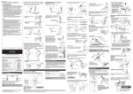
General Safety Information
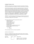
Operation of front derailleur levers
Operation of rear derailleur lever
• Lever A : Shifts from smaller to larger rear sprocket.
Lever A has a click stop at positions ⁄ and ¤.
WARNING
• Obtain and read the service instructions carefully prior to
installing the parts. Loose, worn or damaged parts may cause
the bicycle to fall over and serious injury may occur as a
result. We strongly recommend only using genuine Shimano
replacement parts.
• Obtain and read the service instructions carefully prior to
installing the parts. If adjustments are not carried out
correctly, the chain may come off and this may cause you to
fall off the bicycle which could result in serious injury.
• Use the ST-5700/5703, BL-TT79 with the BR-5700. Do not use
the BR-5700 in combination with previous STI levers for road
riding or with the BL-R770/BL-R550 brake levers for flat
handlebars, otherwise the braking performance provided will
be much too strong.
• Read these Technical Service Instructions carefully, and keep
them in a safe place for later reference.
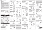
Pass the inner cable through as shown in the illustration, and then
set the inner cable drum into the cable hook.
(FD-5700)
• Lever a : Shifts from smaller to larger front chainring.
Bracket body
Lever b
Cable hook
Lever A
Lever a
start position
⁄ Click
4 3
⁄ : Shifts one sprocket
E.x. : from 3rd to 4th
5
Name plate
If operation of lever a dose not complete the
chainring shift stroke, operate lever a again
for the distance (X') to complete that part of
the lever stroke (X) which was short.
Inner cable drum
••••••••••
• SP41 sealed outer casing (⁄)
••••••••••
f 4 mm
••••••••••••••••••
SP41
CAUTION
4-mm cap
Be sure to install the shifting cable cover before use. If it is not
installed, injury may occur.
¤
Derailleur side
• Lever B : Shifts from larger to smaller rear sprocket.
Press lever B once to shift from a larger to one smaller sprocket.
Plastic cap
Plastic cap or 4-mm cap
⁄
2. Align the stud holes, and then set the special tool (1) in the
position shown in the illustration to press-fit the lever stud.
Unit cover
Cutting the outer casing
Lever B
start position
When lever b is operated, there is
one click where trimming (the noise
prevention mechanism) engages,
and a second stronger click when the
gear shift stroke is completed. After
trimming, the next push will complete
the gear shift stroke.
E-ring groove
When cutting the outer casing, cut the opposite end to the end with
the marking. After cutting the outer casing, make the end round so
that the inside of the hole has a uniform
diameter.
Lever b
start position
Outer stopper
Gear shift
complete
stroke
Lever stroke adjustment
Gears
3mm Allen key
Direct mount seat (M5)
Front derailleur
FD-5700
Front chainwheel
FC-5700
Rear derailleur
• Installation and removal of the pad spacer
FH-5700
Cassette sprocket
CS-5700
Chain
CN-5701
Bottom bracket cable guide
SM-SP17
Cable adjuster
<Installation>
Front
Lever B
Lever b
Lever A
Lever a
Lever B
rear sprocket.
rear sprocket.
chainring.
chainring.
then use the special tool (2) to
install the E-ring.
Be sure leave some excess in the outer casing, even if cutting it
to the full length of the handlebars.
Operate at least 9 times
Pass the inner cable through the cable hole.
The outer casing can be routed in two directions: either through
cable guide (1) (inside) or cable guide 2 (outside).
Replacing the main lever support
Installation:
Note:
Outer stopper
Insert the inner cable so that the inner cable drum goes into the
winder unit as far as it can go.
Outer casing
Insert the main lever support so that it
pushes against the lever body dropprevention notch.
Inner cable
Caution on operation
Main lever support
(1)
Cable hole
Confirm
Make sure the outer casing is firmly
seated in the outer stopper.
(2)
Be sure to read these service instructions in conjunction with the service
instructions for the RD-5700, FD-5700 before use.
Replacing the cable guide
Maintenance
Installation
Installation to the handlebar
Installation of the brake cable
Move the bracket cover forward, and then securely tightening the
mounting nut with a 5 mm Allen key.
Cable used
f 1.6 mm
• Inner cable (stainless steel)
•••••••••••••••••
f 5 mm
Bracket cover
smaller to larger
larger to smaller
smaller to larger
larger to smaller
3. Remove the special tool (1), and
2. Pass the inner cable through, and set the outer casing.
Inner cable
Rear
from
from
from
from
Install with the adjustment bolt tightened.
The adjustment range for the adjustment bolt is six full turns.
Operate lever B at least 9 times to set the lever
to the highest position.
If the chain is on the large front chainwheel
and the larger rear sprocket, the chain will
rub in the front derailleur plate, producing a
characteristic noise. When this happens,
press lever b lightly (to the point where it
clicks); this causes the front derailleur to
move slightly towards the smaller chainwheel,
thereby eliminating the noise.
SM-CA70 / SM-CA50
<Removal>
: Shifts
: Shifts
: Shifts
: Shifts
Chain position
Lever Bb will also move when lever Aa is operated, but be
careful not to apply pressure to lever Bb. Similarly be careful
not to press lever Aa when operating lever Bb. Gears will not
shift when both levers are pressed simultaneously.
Pad spacer
Operation
Lever A
Lever B
Lever a
Lever b
• The correct direction for the lever stud to face is with the E-ring
groove at the top.
• Check that the surface of the bracket body is flush with the top
of the lever stud to ensure that the E-ring can fit into the
groove.
Tightening torque:
1.5 - 2 N·m {13 - 18 in. lbs.}
Outer casing
RD-5700-SS
Freehub
Trim
operation
• Rear lever
Trimming (noise prevention operation)
Do not press-fit the lever stud
from this direction, otherwise it
may damage the bracket body.
Installation bolt
Outer end cap
If the chain is on the smallest front chainring
and a smaller rear sprocket, the chain will rub
in the front derailleur plate, producing a
characteristic noise. When this happens,
press lever a lightly (to the point where it
Movement of the
clicks); this causes the front derailleur to
front derailleur
move slightly towards the larger chainring,
thereby eliminating the noise.
20
Adjustment bolt
SP41
Click
10 mm pad spacer
• Outer stopper
1. Install the outer stopper to the down tube.
Attach the same outer end cap to the cut end of the outer casing.
Click
105
OT-SP41 (SIS-SP41)
Return spring
Wire lead
In order to realize the best performance, we recommend that
the following combination be used.
Outer casing
Do not disassemble the unit cover
at the front, otherwise it may
cause problems with operation.
Lever b
Lever B
Main lever support
Notch
• Lever b : Shifts from larger to smaller front chainring.
5 mm pad spacer (default)
ST-5700
Connector lever
Shifting cable cover
• SP41 outer casing (¤)
If you would like to make the lever stroke larger, remove the pad
spacer.
If you would like to make the lever stroke smaller, replace the
pad spacer with the accessory pad spacer (10 mm).
Shifting lever
assemble the bracket
body and lever body.
Next, insert the end of
the return spring into
the notch.
SEALED
SP41
Series
Assembling the bracket body and lever
body
(2)
SP41
Actual stroke
E.x. : from 4th to 3rd
Shimano Total Integration
Lever stud
Lever body
1. Insert the connector lever into the main lever support, and then
(1)
f 4 mm
¤ : Quick-shifts two sprockets
E.x. : from 3rd to 5th
4 3
ST-5700
Insert the inner cable so that the inner cable drum goes into the
winder unit as far as it can go.
f 1.2 mm
• Inner cable (PTFE inner cable)
Always be sure to remove
the lever stud in this
direction. If it is removed in
the opposite direction, it
may damage the bracket
body.
Note:
Installing the shifting cable
Full gear shift stroke
3
Operate at least once
Pass the inner cable through the cable hole.
The outer casing can be routed in two directions: either through
cable guide (1) (inside) or cable guide 2 (outside).
Lever a
¤ Click
Lever A
start position
Cable used
Technical Service Instructions SI-6TH0A-002
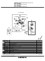
lever stud hole, and then tap it gently with
a plastic mallet to push out the lever stud.
When the lever stud comes out, the
bracket body and lever body can be
disassembled.
Operate lever b once or more to set the lever to
the low position.
Outer casing
Note
• For triple front chainwheel specifications, be sure to read these
Service Instructions in conjunction with the Service
Instructions for the ST-5703 and FD-5703.
• Operation of the levers related to gear shifting should be made
only when the front chainwheel is turning.
• For smooth operation, use the specified outer casing and the
bottom bracket cable guide.
• Grease the inner cable and the inside of the outer casing
before use to ensure that they slide properly.
• Because the high cable resistance of a frame with internal
cable routing would impair the SIS function, this type of frame
should not be used.
• A special grease is used for the gear shifting cable. Do not use
DURA-ACE grease or other types of grease, otherwise they
may cause deterioration in gear shifting performance.
• Parts are not guaranteed against natural wear or deterioration
resulting from normal use.
• For maximum performance we highly recommend Shimano
lubricants and maintenance products.
• For any questions regarding methods of installation,
adjustment, maintenance or operation, please contact a
professional bicycle dealer.
2. Insert an Allen key or similar tool into the
• Front lever
• SLR outer casing
Cable guide
* The illustration shows the right-hand lever.
When removing parts in order to
replace the inner cable, the work can
be carried out more easily if the unit
cover is removed as shown in the
illustration.
Bracket and lever disassembly
Use this hole to replace the cable guide.
1. First use the special tool to remove the E-ring. Use part (B) of the
special tool (2) to align the E-ring with the direction of removal.
Next, set part A against the E-ring and remove the E-ring.
••••••••••••••••••••••••••••
Be sure to leave some excess cable, even if cutting it to the full
length of the handlebars.
E-ring removal direction
Tightening torque:
0.2 N·m {1.8 in. lbs.}
Unit cover
E-ring
Hollow
All levers return to the starting position when released.
Replacing the bracket cover
The tabs on the bracket cover each fit to a matching slot on the
bracket.
Be careful not to cover the cable holes or the unit cover when
wrapping on the handlebar tape. If the handlebar tape covers these
places, it will not be possible to replace the inner cable.
Special E-ring removal tool
5 mm Allen key
Handlebar tape
Unit cover
(1)
(2)
Cable hole
One Holland, Irvine, California 92618, U.S.A. Phone: +1-949-951-5003
Industrieweg 24, 8071 CT Nunspeet, The Netherlands Phone: +31-341-272222
3-77 Oimatsu-cho, Sakai-ku, Sakai-shi, Osaka 590-8577, Japan
* Service Instructions in further languages are available at :
http://techdocs.shimano.com
Please note: specifications are subject to change for improvement without notice. (English)
© Mar. 2010 by Shimano Inc. XBC SZK Printed in Japan.
The correct way for clamp washer
(B) to face is so that the small
hollow on the surface is in the
top-left corner.
CAUTION
Tightening torque:
6 - 8 N·m {52 – 69 in. lbs.}
When installing the components to carbon frame/handle bar surfaces, verify with the manufacturer of the carbon
frame/parts for their recommendation on tightening torque in order to prevent over tightening that can cause
damage to the carbon material and/or under tightening that can cause lack of fixing strength for the components.
(A)
(B)
When removing the E-ring, it may
suddenly spring out, so check the
safety of any nearby people or
objects before removing it.
Note the markings:
R : for right
L : for left
Wipe a little rubbing alcohol inside the
bracket cover to make installation
easier.