1
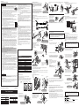
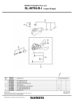
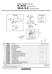
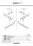
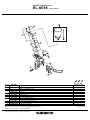
DEORE XT Brake Lever
BL-M785
For Disc Brake
10
1
3
2
4
5
6
7
9
ITEM
NO.
1
* 2
* 3
*
* 4
5
6
7
8
9
10
SHIMANO
CODE NO.
Y8VC98010
Y8VC98050
Y8VC04000
Y8VC04010
Y8VC98060
Y8VC05000
Y8VC98020
Y8VC98030
Y8VC98040
Y8V398040
Y8VC10000
ESMDISCBP
DESCRIPTION
Bleed Screw (M5 x 4.7) & O-Ring
Lid Fixing Bolt (M3) 2 pcs.
R.H. Lid
L.H. Lid
Separator Unit
Lever Axle ø5
Stroke Adjust Screw (M4 x 12) & Plate
R.H. Lever Member Unit
L.H. Lever Member Unit
Lever Axle Fixing Bolt & Cap
Clamp Bolt (M5 x 18)
Funnel & Oil Stopper
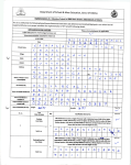
A: Same parts.
B: Parts are usable, but differ in materirals, appearance, finish, size, etc.
Absence of mark indicates non-interchangeability.
Specifications are subject to change without notice.
66
6
BL
-T7
85
BL
-M
BL
-M
98
8
8
INTERCHANGEABILITY
B
A
A
A
B
A
B
A
A
A
A
A
A
A
A
A
Dec.-2011-3158A
© Shimano Inc. I
SI-8JZ0A-004-00
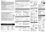
General Safety Information
■ Installation of the brake lever
WARNING
• The 203 mm and 180 mm rotors provide a higher braking force than the 160 mm rotors. Make
sure that you have a complete feel for the braking characteristics before using the brakes.
• Please use extra caution to keep your fingers away from the rotating disc
brake rotor during installing or servicing the wheel. The rotor is sharp enough
to inflict severe injury to your fingers if caught within the openings of moving
rotor.
• The calipers and rotor will become hot when the brakes are operated, so do not touch them
while riding or immediately after dismounting from the bicycle, otherwise you may get burned.
Check that the brake components have cooled down sufficiently before attempting to adjust the
brakes.
• The required braking distance will be longer during wet weather.
Reduce your speed and apply the brakes early and gently.
• If the road surface is wet, the tires will skid more easily. If the tires skid, you may fall off the
bicycle. To avoid this, reduce your speed and apply the brakes early and gently.
• Always make sure that the front and rear brakes are working correctly before you ride the
bicycle.
• If the rotor is cracked or warped, be sure to replace it with a new rotor.
• If the rotor becomes worn down to a thickness of 1.5 mm or so that the aluminum surface
becomes visible, be sure to replace the rotor with a new one.
• Be careful not to allow any oil or grease to get onto the rotor and brake pads, otherwise the
brakes may not work correctly.
• If any oil or grease do get on the pads, be sure to replace them with new
pads. If any oil or grease gets on the rotor, you should clean the rotor. If this
is not done, the brakes may not work correctly.
• Before riding the bicycle, check that the thickness of each pad is 0.5 mm or
more.
• Vapor lock may occur if the brakes are applied continuously. To relieve this
condition, momentarily release the lever.
Vapor lock is a phenomenon in which the oil inside the brake system becomes heated,
which causes any water or air bubbles inside the brake system to expand. This can then
result in a sudden increase in the brake lever stroke.
• Use only genuine Shimano mineral oil. If other types of oil are used, it may cause problems
with brake operation, and cause the system to be unuseable.
• Be sure to use only oil from a freshly-opened container, and do not re-use oil which has been
drained from the bleed nipple. Old oil or already-used oil may contain water which could cause
vapor lock in the brake system.
• Be careful not to let water or air bubbles get into the brake system, otherwise vapor locks may
occur. Be particularly careful when removing the bleed screws.
• If cutting the brake hose in order to adjust the length of the hose, or when changing over the
brake hose from left to right or vice versa, be sure to bleed the air from the hose by carrying
out steps (4), (8) to (12) given in “Adding mineral oil and bleeding air” in the Service
Instructions.
• When turning the bicycle upside down or on its side, the brake system may have some air
bubbles inside the reservoir tank which are still there when the bleed screws are replaced, or
which accumulate in various parts of the brake system when it is used for long periods. This
disc brake system is not designed to be turned upside down. If the bicycle is turned upside
down or on its side, the air bubbles inside the reservoir tank may move in the direction of the
calipers. If the bicycle is ridden in this condition, there is the danger that the brakes may not
operate and a serious accident could occur. If the bicycle has been turned upside down or on
its side, be sure to operate the brake lever a few times to check that the brakes operate
normally before riding the bicycle. If the brakes do not operate normally, adjust them by the
following procedure.
• Inhalation of oil mist or vapors may cause nausea. Cover nose and mouth with a
respirator type mask and use in a well ventilated area.
If mist or vapor is inhaled, go immediately to an area with fresh air. Cover up
with a blanket. Stay warm and stable and seek professional medical advice.
• Do not drink. May cause vomiting or diarrhea.
• Keep out of reach of children.
• Do not cut, heat, weld or pressurize the oil container, as this may cause
explosion or fire.
• Disposal of Used Oil : Follow local county and/or state codes for disposal. Use
care when preparing oil for disposal.
• Directions : Keep the container sealed to prevent foreign objects and moisture
from getting inside, and store it in a cool, dark area away from direct
sunlight or heat.
■ Burn-in period
• Disc brakes have a burn-in period, and the braking force will gradually increase
as the burn-in period progresses. Make sure that you are aware of any such
increases in braking force when using the brakes during the burn-in period. The
same thing will happen when the brake pads or rotor are replaced.
■ When cleaning with a compressor
• If disassembling the caliper body to clean the internal parts using a compressor,
note that moisture from the compressed air may remain on the caliper
components. Let the caliper components dry sufficiently before reassembling the
calipers.
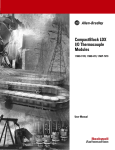
< Front >
< Rear >
Post type
■ Reach adjustment
Tighten the adjust bolt (clockwise) to increase the stroke, and loosen it
(counterclockwise) to decrease the stroke.
Caps
Caps
Caps
Reach adjustment bolt
Reach adjustment bolt
When installing the components to carbon frame/handle bar
surfaces, verify with the manufacturer of the carbon
frame/parts for their recommendation on tightening torque in
order to prevent over tightening that can cause damage to
the carbon material and/or under tightening that can cause
lack of fixing strength for the components.
Brake lever Tightening torque:
6 - 8 N·m {53 - 69 in. lbs.}
< BL-M785 / M666 >
■ Installation of the hose
Refer to the Service Instructions for the SM-BH90-SB brake hose (SI-8JA0A) for details on
installing the hose.
Do not let the hose become twisted when installing. Make sure that the calipers and levers are in
the positions shown in the illustrations.
For C-shaped guides and the usual
type of cable stoppers, use the
special Shimano cable supporter
(sold separately) to secure as
shown in the illustration.
< C-shaped guide > < Usual type of cable stopper >
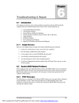
■ Free stroke adjustment
When the free stroke adjustment screw is loosened, the free stroke of the
brake lever will increase, so that you can adjust it to the desired setting.
< BL-M785 >
Tightening torque:
0.3 - 0.5 N·m {2.7 - 4.4 in. lbs.}
Caliper
< For left lever >
< BL-T785 / S700 >
Rotor
Operate the brake lever several times and check whether the brakes operate normally or
not. Also check that there are no oil leaks visible.
Pad contact point
Free stroke
adjustment screw
Note
Pad
• The 203 mm and 180 mm rotors have a larger diameter than the 160 mm rotors
for cross-country bicycles, and so the flexing of these rotors is greater. As a
result, they will interfere with the brake pads.
• If the brake caliper mounting boss and the dropout are not parallel, the rotor and
caliper may touch.
• When the bicycle wheel has been removed, it is recommended that pad spacers
should be installed. The pad spacers will prevent the piston from coming out if
the brake lever is depressed while the wheel is removed.
• If the brake lever is depressed without the pad spacers installed, the pistons will
protrude further than is normal. Use a flat-tipped screwdriver or similar tool to
push back the brake pads, while being careful not to damage the surfaces of the
brake pads. (If the brake pads are not installed, use a flat-shaped tool to push
the pistons straight back in, while being careful not to damage them.)
If it is difficult to push the brake pads or pistons back, remove the bleed screws
and then try again. (Note that some oil may overflow from the reservoir tank at
this time.)
• Use isopropyl alcohol, soapy water or a dry cloth when carrying out cleaning
and maintenance of the brake system. Do not use commercially-available brake
cleansers or silencing agents, as they can cause damage to parts such as
seals.
• Do not remove the pistons when disassembling the calipers.
• Parts are not guaranteed against natural wear or deterioration resulting from
normal use.
• For maximum performance we highly recommend Shimano lubricants and
maintenance products.
< If brake operation is sluggish when the lever is depressed >
Gently depress the brake lever several times and wait for the bubbles to return to the
reservoir tank. It is recommended that you then remove the bleed screws and fill the
reservoir tank with mineral oil until no air bubbles remain.
If the brakes still operate sluggishly, bleed the air from the brake system. (Refer to "Adding
the mineral oil and bleeding air".)
• If fluid leaks occur, immediately stop using the brakes and carry out the appropriate repairs. If
you continue riding the bicycle while fluid is leaking, there is the danger that the brakes may
suddenly stop working.
• If the quick release lever is on the same side as the rotor, there is the danger that it may
interfere with the rotor, so check that it does not interfere.
• It is important to completely understand the operation of your bicycle's brake system. Improper
use of your bicycle's brake system may result in a loss of control or an accident, which could
lead to severe injury. Because each bicycle may handle differently, be sure to learn the proper
braking technique (including brake lever pressure and bicycle control characteristics) and
operation of your bicycle. This can be done by consulting your professional bicycle dealer and
the bicycle's owners manual, and by practicing your riding and braking technique.
• If the front brake is applied too strongly, the wheel may lock and the bicycle may fall forward,
and serious injury may result.
• Shimano disc brake systems are not compatible with tandem bicycles. Because tandem
bicycles have a high overall weight, the load on the brake system increases during brake
operation. If hydraulic disc brakes are used with tandem bicycles, the oil temperature will
become too high and vapor locks or ruptures in the brake hoses may occur, and this will cause
the brakes to fail.
• Obtain and read the service instructions carefully prior to installing the parts. Loose, worn
or damaged parts may cause the bicycle to fall over and serious injury may occur as a result.
We strongly recommend only using genuine Shimano replacement parts.
• Read these Technical Service Instructions carefully, and keep them in a safe place for later
reference.
Install the accessory caps as shown in the illustration to prevent the bolts from loosening.
Secure the brake lever as shown in the illustration. (Check
that the brake lever does not interfere with the shifting lever
during operation. Refer to the Service Instructions for the
shifting lever also. Some types might require the shifting
lever to be installed first, due to the position of the shifting
lever fixing bolts.)
< For right lever >
Contact
Brake lever
At brake lever end
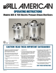
Maintenance
At caliper end
■ Brake pad replacement
Hose
8 mm wrench
Olive
Banjo
■ Mineral oil replacement
Note: This brake system is designed so that as the brake pads become worn,
the pistons gradually move outward to automatically adjust the clearance between
the rotor and the brake pads. Therefore, you need to push the pistons back to
their original positions when replacing the brake pads.
Cover
O-rings
Connector insert
Connecting bolt
Allen key 3 mm
Allen key 4 mm
Tightening torque:
5 - 7 N·m
{44 - 60 in. lbs.}
■ Installation of the calipers and
securing the hose.
Tightening torque
Allen key 3 mm : 5 - 7 N·m {44 - 60 in. lbs.}
Allen key 4 mm : 8 - 10 N·m {69 - 87 in. lbs.}
If oil adheres to the brake pads after oil is added, or if the brake pads are worn down to a
thickness of 0.5 mm, or if the brake pad presser springs are interfering with the rotor,
replace the brake pads.
1. Remove the wheel from the frame, and remove
M666
M666
M666
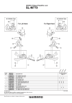
■ Installation of the SL-M780-I and the BL-M785/T785/S700/M666
1. Use a 2 mm Allen key to open the clamp band
Clamp band
Split pin
Set the pad presser spring as shown in
the illustration. (There are left (L) and
right (R) marks on the spring.)
2. Insert the hook of the shifting lever bracket
3. Use a flat-shaped tool to push the pistons straight
Snap ring
M666
The following tools are needed to assemble this product.
Usage location
M666
TL-LR15
Brake lever fixing bolt
Allen key 4 mm
Install the new brake pads, and then install
the pad spacers (red). Make sure that you
do not forget to install the snap rings at
this time also.
Pad with fins
Split pin
Allen key 5 mm
Adapter (post type) fixing bolt
Allen key 5 mm
Brake pad fixing shaft
Allen key 3 mm / Radio pliers
Brake lever bleed screw
Allen key 2.5 mm
Cable supporter
Phillips screwdriver #2
Brake hose fixing bolt
8 mm wrench / Allen key 3 mm, 4 mm
Bleed nipple
7 mm socket wrench
Bleeding
SM-DISC, Syringe
The pads with fins have
fins at the front and back,
so install them as shown in
the illustration.
Tightening torque:
2 - 4 N·m {18 - 35 in. lbs.}
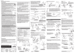
< BR-M666 >
For international-standard mounts, attach adapters to calipers for post-type mounts.
(Separate front and rear adapters are available.)
Install the new brake pads, and then install
the pad spacers (red).
After this, bend open the split pin.
Snap ring
Brake pads
Nut
M666
M666
1. First install the adapter, and then provisionally secure the calipers to the frame. (The calipers
should be able to move sideways.)
Split pin
caliper fixing bolts.
CAUTION
● International standard mounting type
• G01A, G01S, F01A brake pads are designed to reduce the amount of noise which is generated
between the pads and the rotor when the brakes are operated. A longer running-in period is
required for this type of pad compared to G03S/F03C pads.
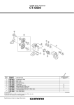
■ Wheel spoke lacing
■ Handling the mineral oil
• Use safety glasses when handling, and avoid contact with eyes. Contact with eyes may result in
irritation.
In the event of eye contact, flush with fresh water and seek medical assistance immediately.
• Use gloves when handling. Contact with skin may cause a rash and discomfort.
In the event of skin contact, wash well with soap and water.
Lace the spokes as shown in Figure 1 below for the left side of the front wheel
(the side where the rotor is installed), and the left and right sides of the rear
wheel, and as shown in Figure 2 below for the right side of the front wheel.
< Front >
Check that the spokes have been laced as shown in the illustration.
A radial assembly cannot be used.
Rear left Rear right
Push
Hook
2. Depress the brake lever so that the rotor is being clamped by the pads, and then tighten the
Front left
2
4. < BR-M785/S700 >
Caliper fixing bolt
Rotating
direction of
wheel
1
Piston
Tool
Rotor fixing lock ring
into the hole in the brake lever bracket, and
then provisionally tighten the special nut and
special bolt to install it to the handlebar.
back in as far as they will go, while being careful not
to twist the pistons. Do not push the pistons with a
sharp tool. The pistons may become damaged.
Pad presser spring
Brake pads
of the brake lever as shown in the illustration.
2. Clean the pistons and surrounding area.
Spacer for bleeding
Installation
Attach a tube with a bag to the bleed nipple, and then open the bleed nipple and
drain out the oil. You can operate the brake lever at this time to help the oil to
drain out. After draining the fluid, pour in fresh brake fluid while referring to
"Adding the mineral oil and bleeding air". Use only genuine Shimano mineral oil.
Dispose of the waste oil according to proper country and/or state disposal
regulations.
Refer to the "Adding the mineral oil and bleeding air" and "Adding
the mineral oil and bleeding air (when using the caliper bleed
screw)" Service Instructions in conjunction with these Service
Instructions.
Brake pads
the brake pads as shown in the illustration.
• Remove the spacer for bleeding (yellow),
and then set the wheel which has the rotor
onto the frame.
• Install the brake pads.
It is recommended that you replace the oil inside the reservoir tank if it becomes
severely discolored.
Tightening torque:
2 - 4 N·m {18 - 35 in. lbs.}
< Rear >
2
Do not install the nut upside-down.
If it is installed upside-down, it will not be
possible to secure the brake lever to the
handlebars, and damage may occur.
Bolt (M5 x 17.5 mm)
Pad spacer (red)
Caliper fixing
bolts
Adapter
fixing bolts
1
Note:
5. Depress the brake lever several times to check that the operation becomes stiff.
Adapter
3. Use a 4 mm Allen key to secure the
shifting lever to the brake lever.
Tightening torque:
4 N·m {35 in. lbs.}
6. Remove the pad spacers, install the wheel, and then check that there is no interference
between the rotor and the caliper. If they are touching, adjust while referring to
"Installation of the caliper".
Front right
4. Use a 4 mm Allen key to secure the clamp
band of the brake lever.
Caliper
■ Adjustment when the pistons are not operating correctly
Adapter
fixing bolts
Technical Service Instructions
SI-8JZ0A-004
Rotor
Fig. 1
Caliper fixing
bolts
Fig. 2
Disc Brake System
● Post mounting type
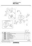
■ Installation of the rotor
In order to realize the best performance, we recommend that the following
combination be used.
Caliper
Brake Lever
BR-M785 / BR-S700 *
/ BR-M666
BL-M785 / BL-T785
BL-S700 / BL-M666
Rotor
SM-RT81 / RT67
Hose
SM-BH90-SB
Cable Supporter
SM-HANG
SM-DB-OIL
Mineral Oil
Brake pad unit
Without fins
With fins
Resin Pads
G01A / G01S
F01A
Metal Pads
*
G03S
F03C
The BR-S700 is for use with resin pads (G01A, G01S, F01A)
only.
The caliper mechanism includes two pistons. If these pistons do not operate properly or if
they protrude unevenly, or if the brake pads remain in contact with the rotor, adjust the
pistons by the following procedure.
SM-RT81L / RT67L (203mm)
SM-RT81M / RT67M (180mm)
SM-RT81S / RT67S (160mm)
Rotor fixing
lock ring
Tightening torque:
6 - 8 N·m {53 - 69 in. lbs.}
3. Install the brake pads and the pad spacers (red).
4. Depress the brake lever as far as it will go, and then operate it several more times so
Provisionally install the caliper to the frame
(so that the caliper can move sideways),
depress the brake lever so that the rotor is
being clamped by the pads, and then
tighten the caliper fixing bolts.
This service instruction explains how to use and maintain the Shimano bicycle parts
which have been used on your new bicycle.
For any questions regarding your bicycle or other matters which are not related to
Shimano parts, please contact the place of purchase or the bicycle manufacturer.
that the two pistons all move to their initial positions.
5. Remove the pad spacer, install the wheel, and then check that there is no interference
between the rotor and the brake pads. If they are touching, loosen the installation bolts
and adjust so that they are no longer touching.
One Holland, Irvine, California 92618, U.S.A. Phone: +1-949-951-5003
Industrieweg 24, 8071 CT Nunspeet, The Netherlands Phone: +31-341-272222
TL-LR15
Tightening torque:
40 - 50 N·m {350 - 435 in. lbs.}
1. Remove the wheel and the brake pads. Clean the pistons and surrounding area.
2. Use a flat-shaped tool to push the pistons straight back in as far as they will go, while
being careful not to twist the pistons. Do not push the pistons with a sharp tool. The
pistons may become damaged.
< Front >
Tightening torque:
6 - 8 N·m {53 - 69 in. lbs.}
Tightening torque:
6 - 8 N·m {53 - 69 in. lbs.}
Caliper fixing
bolts
3-77 Oimatsu-cho, Sakai-ku, Sakai-shi, Osaka 590-8577, Japan
* Service Instructions in further languages are available at :
http://techdocs.shimano.com
Please note: specifications are subject to change for improvement without notice. (English)
© Nov. 2011 by Shimano Inc. XBC SZK