1
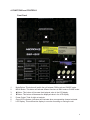
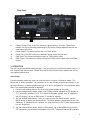
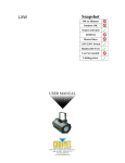
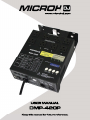
1 1. INTRODUCTION AND UNPACKING Thank you for purchasing the MICROH DMP-420P effect fixture. For your own safety and knowledge, please read this manual before installing or operating the device. This manual covers the important information on installation and applications. Please install and operate the fixture according to instructions. Meanwhile, please keep this manual for future reference. The MICROH DMP-420P effect fixture is manufactured following CSA standards, complying with international standard DMX512 protocol. This fixture is applicable but not limited to large-scale live performances, theater, studio, nightclubs and discos. The MICROH DMP-420P effect fixture features a two colour laser, strobe and a moonflower effect. Please carefully unpack it when you receive the fixture and check if it was damaged during the transportation. Please check whether the following items are included inside the box: Fixture – One Power Cord – One User Manual – One 2. SAFTEY INSTRUCTIONS This device has been delivered in safe working condition. In order to maintain this condition and to ensure safe operation, it is absolutely necessary for the user to follow the safety instructions and warning notes written in this user manual. If the device has been exposed to temperature changes, do not switch it on immediately. The arising condensation could damage the device. Leave the device switched off until it has reached room temperature, and is dry. This device falls under protection-class I, therefore it is essential that the device be grounded. The electrical connection must be carried out by a qualified technician. The device should only be used with rated voltage and frequency. Make sure that the available voltage is not higher than 120V as stated at the end of this manual. Make sure the power cord is never crimped or damaged in any way, as this could cause shock and damage. If your power cord is damaged in any way, please purchase a new cable from your local MICROH dealer. Always disconnect power, when the device is not in use or before cleaning it. Never pull out the plug by tugging the power cord. 2 During initial start-up, some smoke or smell may arise. This is a normal process, and does not necessarily mean that the device is defective. It should decrease gradually. Fixtures cannot be installed on or near combustible substances. Keep more than 50cm distance from wall for proper ventilation and air flow. If your fixture is or has become damaged in any way, it shall be exclusively replaced or repaired by the manufacturer to avoid any hazard. 3. MOUNTING AND INSTALLATION Caution: For added protection, mount the fixtures in areas outside walking paths, seating areas, or in areas were the fixture might be reached by unauthorized personnel. Before mounting the fixture to any surface, make sure that the installation area can hold a minimum point load of 10 times the device’s weight. Fixture installation must always be secured with a secondary safety attachment, such as an appropriate safety cable. Never stand directly below the device when mounting, removing, or servicing the fixture. Be sure this fixture is kept at least 0.5m (1.5 ft.) away from any flammable materials (decoration etc.). Always use and install the supplied safety cable as a safety measure to prevent accidental damage and/or injury in the event the clamp fails. Mounting Points: Overhead mounting requires extensive experience, including calculating working load limits. A knowledge of the installation material being used and periodic safety inspection of all installation material and the fixture are all imperative and should only be performed by a qualified technician. Improper installation can result in bodily injury and damage. Be sure to complete all rigging and installation procedures before connecting the main power cord to the appropriate wall outlet. 3 4. FUNCTIONS and CONTROLS Front Panel 5 6 7 1 1. 2. 3. 4. 5. 6. 7. 2 3 4 Mode Button: This button will switch the unit between DMX mode and CHASE mode. MENU Button: This button will activate different functions in DMX mode or CHASE mode. ڸButton: This button will increase the displayed value in the LCD display. ۂButton: This button will decrease the displayed value in the LCD display. Power Output: Total of eight out sockets. Green LED Indicators: Indicators will illuminate when corresponding channel activated. LCD Display: This multifunction display is a monitor for setting or running the unit. 4 Rear Panel 8 9 10 11 8. 9. 10. 11. 12. 12 Channel Fuses: Each of the four channels is protected by a 10A fuse. These fuses prevent unit from overloading and damaging. Be sure to always replace them with the exact same type fuses. Power Switch: This switch controls the unit’s main power. Power Cord: Plug this cord into a rated main power supply for your area. DMX Input: This connector allows the input of DMX control signal. DMX Output: This connector allows the output of DMX control signal to the next DMX device 3. OPERATION The unit has two switchable working modes. It can be used as a four-channel chaser or as a 1, 2, or 4 channel DMX dimmer pack. Please follow up the instructions below to operate the unit for your desired performance. CHASE MODE Use this operating mode only when you want the device to act as a 4-channel chaser. This device has 16 built-in programs. You can select to run any of these programs specifically, or set the unit to chase in a random sequence among all 16 built-in programs for a more dramatic show effect. The chase speed can also be adjusted. 1. Connect your lighting effect to any of the eight power sockets on the pack. 2. Use the mode button to select chase mode: Chase mode is indicated in LCD display as “PA” followed by numbers 01-16. “PA” stands for Program Applied. If an “A” appears in the LCD display, you are in DMX mode, “A” stands for address. 3. Set you desired chase pattern: Once you have selected the chase function, use the MENU button to select your desired chase. The chase pattern is represented in the LCD display by “P” followed by two numbers. You may select any of the 16 built-in programs to run at a single time. 4. Set your desired chase speed: While in chase mode, tap on the MENU button until the ³63´IROORZHGE\WZRQXPEHUVLVGLVSOD\HGLQWKH/&'7KHQXVHWKHŸaQGźEXWWRQVWR 5 adjust the chase speed. A value of 99 will give you the fastest chase speed (about one step per 0.1 second). A value of 01 will give you the slowest chase speed (one step per 30 second). 5. You may now change the light intensity: Use the MENU button to select “d” on the LCD. 8VHWKHŸ aQGźbuttons to change the light output intensity. 00 will give the lowest output and 99 will give you full intensity. DMX MODE Use this operating mode if you plan to use your pack as a DMX dimmer. This function will allow you to turn on and control the intensity of non-DMX with the use of a DMX controller. On, Off, and Dimming functions can be performed through this pack. You may also set your dimmer pack to function as a 1, 2, or 4 channel DMX dimmer pack, which means you can combine the output functions. DMX Operation 1. Connect a DMX controller to your dimmer pack via the 3-pin XLR connector. 2. Connect your lighting effect to any of the eight power sockets on the front of the pack. 3. Decide if you are going to use your dimmer pack as 1, 2, or 4 channels. This function allows you to: a. Control the output to all four outlets with one DMX channel. b. Group outlet channels one and two and group outlets channels three and four. The first group will be controlled by one DMX channel and the second group will be controlled by another DMX channel. This gives the pack a DMX value of two. c. The default setting is a four channel DMX switcher, each channel is controlled by one DMX channel. 4. To change the channel function mode be sure that you are in DMX mode. Use the 0(18EXWWRQWRVHOHFW³&+´IROORZHGE\WZRGLJLWV7KHQXVHWKHŸDQGźEXWWRQVWR change the setting from 01, 02, or 04. Your dimmer pack is initially set as a four channel DMX switcher. 5. The dimmer pack is initially set to be activated by DMX address one. To change this setting be that sure you are in DMX mode. Use the MENU button to select the address settings, this will be indicated by an “A” in the first character of the LCD IROORZHGE\WKUHHQXPEHUV8VHWKHŸDQGźEXWWRQVWRVHOHFW\RXUGHVLUHG'0; address. Remember the DMX address tells your DMX controller what channel to activate the pack’s functions. 6. Once you have set the pack’s DMX address be sure that your controller’s address matches that of the pack’s. 7. Your pack will now operate as DMX dimmer, you may control the light output intensity through your DMX controller. 0 will give no output and 100 will give you full output. 4. TECHNICAL SPECIFICATIONS Power supply: 100-240V AC 50/60Hz 1440W Fuse: 250V 6.3A ITEM DIMENSION: 310x250x75MM (12.2”x9.8”x2.95”) ITEM WEIGHT: 3KGS (6.6Lbs) 6 5. MAINTENANCE AND CLEANING The following points have to be considered during the inspection: 1) All screws for installing the device or parts of the device must be tightly connected, and must not be corroded. 2) There must not be any deformations on the housing, colour lenses, fixations or installation spots (ceiling, suspension, trussing). 3Mechanically moved parts must not show any traces of wearing and must not rotate with unbalances. 4㸧The electric power supply cables must not show any damage, material fatigue or sediments. Further instructions depending on the installation spot and usage must be handled by a skilled installer or technician. Any safety issues must be resolved. In order to keep the fixture in good condition and extend the life, we suggest regular cleaning to the fixture. 1) Clean the inside and outside lens each week to avoid the light output from darkening due to accumulation of dust, dirt, etc. 2) Clean the fan each week. 3) A detailed electrical check by approved technician every three months is advised. Ensure the circuit contacts are in good condition. We recommend a frequent cleaning of the device. Please use a moist, lint-free cloth. Never use alcohol or solvents. There are no serviceable parts inside the device. Please refer to the instructions under “Installation instructions”. Should you need any spare parts, please order genuine MICROH parts from your local dealer. 7 IF YOU SHOULD EXPERIENCE ANY PROBLEMS OR ISSUES PLEASE CONTACT MICROH PROFESSIONAL PRODUCTS BY EMAIL AT [email protected] In the event that your unit is defective in any way, please contact your local dealer to obtain an RA number for service repair. DISCLAIMER – MICROH believes that the information contained within this user manual is accurate. However, Microh is not responsible for any error or addendums to this manual. If you have any comments or general suggestions on how this manual can be improved please contact [email protected]. Thank you. 8 NOTES: 9 NOTES: 10