1
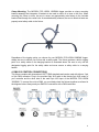
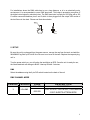
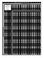
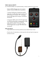
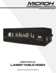
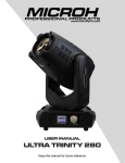
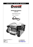
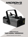
1
1. INTRODUCTION AND UNPACKING
Thank you for purchasing the MICROH FOG HORN 1200 fogger. For your own safety and
knowledge, please read this manual before installing or operating the device. This manual covers
the important information on installation and applications. Please install and operate the fixture
according to instructions. Meanwhile, please keep this manual for future reference.
The MICROH FOG HORN 1200 fogger is manufactured following CSA standards, complying with
international standard DMX512 protocol. This fixture is applicable but not limited to large-scale
live performances, theater, studio, nightclubs and discos.
Please carefully unpack it when you receive the fogger and check if it was damaged during the
transportation. Please check whether the following items are included inside the box:
Fixture – One
Power Cord – One
User Manual – One
Wireless Remote – One
Wired Remote - One
2. SAFTEY INSTRUCTIONS
Safety Notes Read all the following Safety Notes before working with this product. These notes
include important information about the installation, usage, and maintenance of this product.
This product contains no user-serviceable parts. Any reference to servicing in this User Manual
will only apply to properly trained MICROH certified technicians. Do not open the housing or
attempt any repairs.
All applicable local codes and regulations apply to proper installation of this product.
Personal Safety
· Always disconnect this product from its power source before servicing.
· Always connect this product to a grounded circuit to avoid the risk of electrocution.
· Do not touch this product’s housing during operation because it may be very hot.
· Do not drink or become in contact with the fog fluid. If you do, call your local emergency service
(911 in the CDA/US) for help.
· Mount this product in a location with adequate ventilation, at least 20 in (50 cm) from adjacent
surfaces.
· Make sure there are no flammable materials close to this product while it is operating.
· When hanging this product, always secure to a fastening device using a safety cable
(not included).
Power and Wiring
· Make sure the power cord is not crimped or damaged.
· Always make sure you are connecting this product to the proper voltage in accordance with the
specifications in this manual or on the product’s specification label.
· Never connect this product to a dimmer pack or rheostat.
· Never disconnect this product by pulling or tugging on the power cable.
2
Operation
· Do not operate this product if you see damage to the housing, fluid tank, or cables. Have the
damaged parts replaced by an authorized technician at once.
· Be sure that no ventilation slots on the product’s housing are blocked.
· The fog exits the nozzle at a very high temperature. Keep a minimum distance of 6.5ft (2 m)
from the nozzle to the nearest object.
· The product’s nozzle is very hot during operation and it remains hot for a long time after
operation has stopped.
· The maximum ambient temperature is 104 °F (40 °C). Do not operate this product at a higher
temperature.
· In the event of a serious operating problem, stop using this product immediately!
· Do not add perfume, alcohol, gasoline, or any other flammables to the fog fluid.
· Operates best with MICROH’s ‘MAXIMUM’ water-based High Density Fog Fluid (HDF).
3. MOUNTING AND INSTALLATION
Caution: For added protection, mount the fixtures in areas outside walking paths, seating areas,
or in areas were the fixture might be reached by unauthorized personnel. Before mounting the
fixture to any surface, make sure that the installation area can hold a minimum point load of 10
times the device’s weight. Fixture installation must always be secured with a secondary safety
attachment, such as an appropriate safety cable. Never stand directly below the device when
mounting, removing, or servicing the fixture.
Whether installing inverted on a truss / ceiling or set on a flat level surface (see illustration
below). Be sure this fixture is kept at least 0.5m (1.5 ft.) away from any flammable materials
(decoration etc.). Always use and install the supplied safety cable as a safety measure to prevent
accidental damage and/or injury in the event the clamp fails.
Mounting Points: Overhead mounting requires extensive experience, including calculating
working load limits. A knowledge of the installation material being used and periodic safety
inspection of all installation material and the fixture are all imperative and should only be
performed by a qualified technician. Improper installation can result in bodily injury and damage.
Be sure to complete all rigging and installation procedures before connecting the main power
cord to the appropriate wall outlet.
3
Clamp Mounting: The MICROH FOG HORN 1200DMX fogger provides a unique mounting
bracket assembly that integrates 2 brackets to be used to mount on a truss or the floor. When
mounting this fixture to truss, be sure to secure an appropriately rated clamp to the included
bracket fitted through the center hole. As an added safety measure, be sure to attach at least one
properly rated safety cable to the fixture.
Regardless of the rigging option you choose for your MICROH FOG HORN 1200DMX fogger,
always be sure to secure your fixture with a safety cable. The fixture provides a built-in rigging
point for a safety cable on the hanging bracket as illustrated above. Be sure to only use the
designated rigging point for the safety cable and never secure a safety cable to a carrying
handle.
4. DMX-512 CONTROL CONNECTIONS
This fixture complies with international USITT DMX standards and can be used with either a 3 pin
or 5pin DMX connector. Plug in the provided 3pin XLR cable to the female 3pin XLR output of
your controller and the other side to the male 3pin XLR input of the MICROH FOG HORN
1200DMX. To connect the units to DMX, you must daisy chain the fixtures together as referred in
the diagram below. Always end your DMX-512 connection with a DMX terminator.
4
For installations where the DMX cable has to run a long distance, or is in an electrically noisy
environment, it is recommended to use a DMX terminator. This helps in preventing corruption of
the digital control signal by electrical noise. The DMX terminator is simply an XLR plug with a 120
Ω resistor connected between pins 2 and 3,which is then plugged into the output XLR socket of
the last fixture in the chain. Please see illustrations below.
120Ω
2
3
1
PIN 3
PIN 2
5. SETUP
Be sure the unit is unplugged from the power source, remove the cap from the tank, and add the
‘MAXIMUM’ fog fluid up to fluid fill line. Be sure to not over fill the tank. Replace the cap and plug
unit in.
Turn the power switch on; you will notice the tank lights up RED. Once the unit is ready for use,
the illuminated tank will change to BLUE. Heat-up will take 3 minutes.
DMX
Select the address using the 9 pin DIP switch located on the back of the unit
DMX CHANNEL MODE
Channel Function
1
VOLUME
Value
DESCRIPTION
000 - 004
NO FUNCTION
005-255
FULL OUTPUT FOR 30 SEC, CONTINUOUS
5 SEC BURSTS AFTERWARDS
5
DIP SWITCH POSITION
#9
DMX DIP
SWITCH SET #8
#7
0=OFF
#6
1=ON
#1 #2 #3 #4 #5
0 0 0 0 0
1 0 0 0 0
0 1 0 0 0
1 1 0 0 0
0 0 1 0 0
1 0 1 0 0
0 1 1 0 0
1 1 1 0 0
0 0 0 1 0
1 0 0 1 0
0 1 0 1 0
1 1 0 1 0
0 0 1 1 0
1 0 1 1 0
0 1 1 1 0
1 1 1 1 0
0 0 0 0 1
1 0 0 0 1
0 1 0 0 1
1 1 0 0 1
0 0 1 0 1
1 0 1 0 1
0 1 1 0 1
1 1 1 0 1
0 0 0 1 1
1 0 0 1 1
0 1 0 1 1
1 1 0 1 1
0 0 1 1 1
1 0 1 1 1
0 1 1 1 1
1 1 1 1 1
0
0
0
0
1
2
3
4
5
6
7
8
9
10
11
12
13
14
15
16
17
18
19
20
21
22
23
24
25
26
27
28
29
30
31
DMX Address Quick Reference Cahrt
DIP SWITCH POSITION
0 0 0 0 0 0 0 1 1
0 0 0 1 1 1 1 0 0
0 1 1 0 0 1 1 0 0
1 0 1 0 1 0 1 0 1
32
33
34
35
36
37
38
39
40
41
42
43
44
45
46
47
48
49
50
51
52
53
54
55
56
57
58
59
60
61
62
63
64
65
66
67
68
69
70
71
72
73
74
75
76
77
78
79
80
81
82
83
84
85
86
87
88
89
90
91
92
93
94
95
96
97
98
99
100
101
102
103
104
105
106
107
108
109
110
111
112
113
114
115
116
117
118
119
120
121
122
123
124
125
126
127
128
129
130
131
132
133
134
135
136
137
138
139
140
141
142
143
144
145
146
147
148
149
150
151
152
153
154
155
156
157
158
159
160
161
162
163
164
165
166
167
168
169
170
171
172
173
174
175
176
177
178
179
180
181
182
183
184
185
186
187
188
189
190
191
192
193
194
195
196
197
198
199
200
201
202
203
204
205
206
207
208
209
210
211
212
213
214
215
216
217
218
219
220
221
222
223
224
225
226
227
228
229
230
231
232
233
234
235
236
237
238
239
240
241
242
243
244
245
246
247
248
249
250
251
252
253
254
255
256
257
258
259
260
261
262
263
264
265
266
267
268
269
270
271
272
273
274
275
276
277
278
279
280
281
282
283
284
285
286
287
288
289
290
291
292
293
294
295
296
297
298
299
300
301
302
303
304
305
306
307
308
309
310
311
312
313
314
315
316
317
318
319
1
0
1
0
1
0
1
1
1
1
0
0
1
1
0
1
1
1
1
0
1
1
1
1
320
321
322
323
324
325
326
327
328
329
330
331
332
333
334
335
336
337
338
339
340
341
342
343
344
345
346
347
348
349
350
351
352
353
354
355
356
357
358
359
360
361
362
363
364
365
366
367
368
369
370
371
372
373
374
375
376
377
378
379
380
381
382
383
384
385
386
387
388
389
390
391
392
393
394
395
396
397
398
399
400
401
402
403
404
405
406
407
408
409
410
411
412
413
414
415
416
417
418
419
420
421
422
423
424
425
426
427
428
429
430
431
432
433
434
435
436
437
438
439
440
441
442
443
444
445
446
447
448
449
450
451
452
453
454
455
456
457
458
459
460
461
462
463
464
465
466
467
468
469
470
471
472
473
474
475
476
477
478
479
480
481
482
483
484
485
486
487
488
489
490
491
492
493
494
495
496
497
498
499
500
501
502
503
504
505
506
507
508
509
510
511
6
TIMER / MANUAL REMOTE
The FOGHORN1200DMX can be operated manually, or with the included timer remote control.
- When the GREEN LED lights up the unit is ready for
operation. Press the GREEN button to manually fog
- To engage CONTINUOUS FOGGING press the RED
toggle switch. The RED LED will lights up indicating that
the CONTINUOUS FOGGING is ‘ON’. To disengage,
press the RED toggle switch once again. The RED LED
will extinguish.
- To engage the TIMER, press the YELLOW toggle switch.
The YELLOW LED will lights up indicating that the TIMER
is ‘ON’. Adjust the 3 dials to set your INTERVAL,
DURATION and OUTPUT. To disengage, press the
YELLOW toggle switch once again. The YELLOW LED
will extinguish.
WIRELESS REMOTE
- Plug the wired receiver into the fog machines 5-pin port labeled “Remote Control”
- Press the either of the fog buttons, and the fog machine will output fog for as long as you
hold down the button.
7
9. TECHNICAL SPECIFICATIONS
Heat up Time: 3-5 Mins
Tank Capacity: 2.5L
Spraying Distance: 15m
Output: 10000 cu.ff/min
Voltage: 110V AC 60Hz
Power: 1400W
Weight: 13.1Lbs
10. MAINTENANCE AND CLEANING
The following points have to be considered during the inspection:
1) All screws for installing the device or parts of the device must be tightly connected, and must
not be corroded.
2) There must not be any deformations on the housing, colour lenses, fixations or installation
spots (ceiling, suspension, trussing).
3) Mechanically moved parts must not show any traces of wearing and must not rotate with
unbalances.
4)The electric power supply cables must not show any damage, material fatigue or sediments.
Further instructions depending on the installation spot and usage must be handled by a skilled
installer or technician. Any safety issues must be resolved.
In order to keep the fixture in good condition and extend the life, we suggest regular cleaning to
the fixture.
1) Clean the inside and outside lens each week to avoid the light output from darkening due to
accumulation of dust, dirt, etc.
2) Clean the fan each week.
3) A detailed electrical check by approved technician every three months is advised. Ensure the
circuit contacts are in good condition.
8
We recommend a frequent cleaning of the device. Please use a moist, lint- free cloth. Never use
alcohol or solvents.
There are no serviceable parts inside the device. Please refer to the instructions under
“Installation instructions”.
Should you need any spare parts, please order genuine MICROH parts from your local dealer.
IF YOU SHOULD EXPERIENCE ANY PROBLEMS OR ISSUES PLEASE CONTACT MICROH
PROFESSIONAL PRODUCTS BY EMAIL AT [email protected]
In the event that your unit is defective in any way, please contact your local dealer to
obtain an RA number for service repair.
Disclaimer: MICROH
believes that the information contained in this manual is
accurate in all respects. However, MICROH assumes no responsibility for any errors or
omissions in this document. MICROH reserves the right to revise and make changes to
the content of this document without obligation that MICROH notify any person or
company of such revision or changes. This does not in any way constitute a commitment
by MICROH to make such changes. MICROH may issue a revision of this manual or a
new edition to incorporate such changes.
9
Notes:
10