1
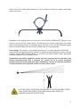
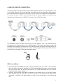
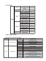
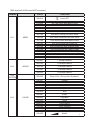
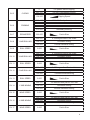
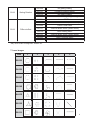
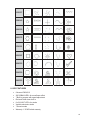
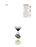
1
1. INTRODUCTION AND UNPACKING
Thank you for purchasing the MICROH PLASMAWAVE effect fixture. For your own safety and
knowledge, please read this manual before installing or operating the device. This manual covers
the important information on installation and applications. Please install and operate the fixture
according to instructions. Meanwhile, please keep this manual for future reference.
The MICROH PLASMAWAVE effect fixture is manufactured following CSA standards, complying
with international standard DMX512 protocol. This fixture is applicable but not limited to largescale live performances, theater, studio, nightclubs and discos.
The MICROH PLASMAWAVE laser features a RGB laser effect. Please carefully unpack it when
you receive the fixture and check if it was damaged during the transportation. Please check
whether the following items are included inside the box:
Fixture – One
Power Cord – One
User Manual – One
2. SAFTEY INSTRUCTIONS
This device has been delivered in safe working condition. In order to maintain this condition and
to ensure safe operation, it is absolutely necessary for the user to follow the safety instructions
and warning notes written in this user manual.
If the device has been exposed to temperature changes, do not switch it on immediately. The
arising condensation could damage the device. Leave the device switched off until it has reached
room temperature, and is dry.
This device falls under protection-class I, therefore it is essential that the device be grounded.
The electrical connection must be carried out by a qualified technician.
The device should only be used with rated voltage and frequency. Make sure that the available
voltage is not higher than 120V as stated at the end of this manual.
Make sure the power cord is never crimped or damaged in any way, as this could cause shock
and damage. If your power cord is damaged in any way, please purchase a new cable from your
local MICROH dealer. Always disconnect power, when the device is not in use or before cleaning
it. Never pull out the plug by tugging the power cord.
During initial start-up, some smoke or smell may arise. This is a normal process, and does not
necessarily mean that the device is defective. It should decrease gradually. Please do not project
the beam onto combustible substances.
2
Fixtures cannot be installed on or near combustible substances. Keep more than 50cm distance
from wall for proper ventilation and air flow. If your fixture is or has become damaged in any way,
it shall be exclusively replaced or repaired by the manufacturer to avoid any hazard.
3. MOUNTING AND INSTALLATION
Caution: For added protection, mount the fixtures in areas outside walking paths, seating areas,
or in areas were the fixture might be reached by unauthorized personnel. Before mounting the
fixture to any surface, make sure that the installation area can hold a minimum point load of 10
times the device’s weight. Fixture installation must always be secured with a secondary safety
attachment, such as an appropriate safety cable. Never stand directly below the device when
mounting, removing, or servicing the fixture.
Whether installing inverted on a truss / ceiling or set on a flat level surface (see illustration
below). Be sure this fixture is kept at least 0.5m (1.5 ft.) away from any flammable materials
(decoration etc.). Always use and install the supplied safety cable as a safety measure to prevent
accidental damage and/or injury in the event the clamp fails.
Mounting Points: Overhead mounting requires extensive experience, including calculating
working load limits. A knowledge of the installation material being used and periodic safety
inspection of all installation material and the fixture are all imperative and should only be
performed by a qualified technician. Improper installation can result in bodily injury and damage.
Be sure to complete all rigging and installation procedures before connecting the main power
cord to the appropriate wall outlet.
Clamp Mounting: The MICROH PLASMAWAVE provides a unique mounting bracket assembly
that integrates 2 brackets to be used to mount on a truss or the floor. When mounting this fixture
to truss, be sure to secure an appropriately rated clamp to the included bracket fitted through the
3
center hole. As an added safety measure, be sure to attach at least one properly rated safety
cable to the fixture.
Regardless of the rigging option you choose for your MICROH PLASMAWAVE, always be sure
to secure your fixture with a safety cable. The fixture provides a built-in rigging point for a safety
cable on the hanging bracket as illustrated above. Be sure to only use the designated rigging
point for the safety cable and never secure a safety cable to a carrying handle.
Proper Usage: This product is for overhead mounting only. For safety purposes, MICROHDJ
recommends mounting lighting effect products on steady elevated platforms or sturdy overhead
supports using suitable hanging clamps. In all cases, use safety cables. Obtain appropriate
mounting hardware from your lighting vendor.
International laser safety regulations require that laser products must be operated in the
fashion illustrated below, with a minimum of 3 meters (9.8 ft) of vertical separation
between the floor and the lowest laser light. Additionally, 3 meters of horizontal separation
is required between laser light and audience or other public spaces.
CAUTION! USE OF CONTROLS, ADJUSTMENTS, OR PROCEDURES OTHER
THAN THOSE SPECIFIED IN THIS USER MANUAL MAY RESULT IN
HAZARDOUS RADIATION EXPOSURE.
4
4. DMX-512 CONTROL CONNECTIONS
This fixture complies with international USITT DMX standards and can be used with either a 3 pin
or 5 pin DMX connector. Plug in the provided 3 pin XLR cable to the female 3-pin XLR output of
your controller and the other side to the male 3-pin XLR input of the MICROH PLASMAWAVE.
To connect the units to DMX, you must daisy chain the fixtures together as referred in the
diagram below. Always end your DMX-512 connection with a DMX terminator.
For installations where the DMX cable has to run a long distance, or is in an electrically noisy
environment, it is recommended to use a DMX terminator. This helps in preventing corruption of
the digital control signal by electrical noise. The DMX terminator is simply an XLR plug with a 120
ȍUHVLVWRUFRQQHFWHGEHWZHHQSLQVDQGZKLFKLVWKHQSOXJJHGLQWRWKHRXWSXW;/5VRFNHWRI
the last fixture in the chain. Please see illustrations below.
120¡
2
3
1
PIN 3
PIN 2
ILDA Control Mode
z
z
This unit has the ILDA DB25 port, and it can be controlled by the PC, There is auto transform
set in the inside of the unit to transform the ILDA and preprogrammed show. when connecting
with the 25 pin cable, the unit will be control by PC, when disconnect the unit, it will be
preprogrammed program controlࠋ
In theory, as long as the ILDA DB25 is connected, It can control this unit. In the reality, some
laser software may not control this unit. Pins 4 and17 on the output of the card are not
connected. In fact this is an easy problem. As long as you connect them. It can control this
unit.
5
5. SETUP MENU
SIGNAL
MIRROR
AUTO
MODE
SOUND
SENSITIVITY
001
SLAVE
SY:N SX:N
SY:Y SX:Y
LASER UNIVERSAL
BURST GRATING
LASER LUMIA
SCANNED BEAM
LASER 3D
MIXED 5 EFFECT
MIXED 5 EFFECT
BURST GRATING
LASER LUMIA
SCANNED BEAM
LASER 3D
MIXED 5 EFFECT
ŲŲŲŲŲŲŲŲŲŲ
6. DMX CHANNEL MODES
DMX chart with ILDA control connected
CHANNEL
CH1
CH2
Grating Rotation
Grating Effect
VALUE
DESCRIPTION
000-004
No grating rotating
005-127
Clockwise grating rotating
128-133
No grating rotating
134-255
Counter clockwise grating rotating
000-031
Laser 3D Effect
032-063
Scanned Beam Effect (Pattern Effect)
064-095
Laser Lumia Effect
096-127
Scanned Beam Effect (Pattern Effect)
128-159
Burst Grating Effect
160-191
Scanned Beam Effect (Pattern Effect)
192-223
Laser Universal Effect
224-255
Scanned Beam Effect (Pattern Effect)
6
DMX chart with ILDA control NOT connected
CHANNEL
CH 1
MODE
VALUE
FUNCTION
000-018
Laser OFF
019-036
AUT Auto Show with Mixed 5 effect
037-054
A3D Laser 3D Effect Auto Show
055-072
AUB Scanned Beam Effect Auto Show
073-090
AUL Laser Lumia Effect Auto Show
091-108
AUN Burst Grating Effect Auto Show
109-126
AUO Laser Universal Effect Auto Show
127-144
SOU Sound Show with Mixed 5 Effect
145-162
S3D Sound show with LASER 3D
163-180
SOB Sound show with Scanned Beam
181-198
SOL Sound show with LASER LUMIA
199-216
SON Sound show with Burst Grating
217-234
SOO Sound show with Laser Universal
235-255
DMX MODE
000-051
208-255
1 Group Patterns.
2 Group Patterns
3 Group Patterns
4 Group Patterns
5 Group Patterns
000-255
Every 16 for 1 Group, total 16 patterns.
000-007
Original
008-015
Red
016-023
Green
024-031
Yellow
032-039
Blue
040-047
Purple
048-055
Light Blue
056-063
White
064-111
Color Rolling
112-159
Color Jumping
160-127
Color Moving
208-255
Strobe
052-103
CH 2
GROUP
104-155
156-207
CH 3ǂǂ
PATTERN
CH 4
COLOR
7
CH 5
CH 6
CH 7
CH 8
CH 9
CH 10
CH 11
CH 12
CH 13
CH 14
CH 15
CH 16
CH 17
CLIPING
ZOOMING
ZOOM SPEED
Y AXIS ROLLING
ROLL SPEED
X AXIS ROLLING
ROLL SPEED
Z AXIS ROLLING
ROLL SPEED
Y AXIS MOVING
MOVE SPEED
X AXIS MOVING
MOVE SPEED
0
Full pattern without clipping
001-127
0%~99% fixed pattern clipped
128-255
Clipping Speed
000-127
100%-5% fixed pattern zoomed
128-169
Zoom IN
170-209
Zoom OUT
210-255
Alternately Zooming
000-255
Fast to Slow
000-127
0 -359 degree fixed Y axis rolled
128-191
Clockwise rolling
192-255
Counter clockwise rolling
0-255
Fast to Slow
000-127
0 -359 degree fixed X axis rolled
128-191
Clockwise rolling
192-255
Counter clockwise rolling
0-255
Fast to Slow
000-127
0 -359 degree fixed Z axis rolled
128-191
Clockwise rolling
192-255
Counter clockwise rolling
0-255
Fast to Slow
000-127
128 different fixed position on X axis
128-191
Clockwise moving
192-255
Counter clockwise moving
0-255
Fast to Slow
000-127
128 different fixed position on Y axis
128-191
Clockwise moving
192-255
Counter clockwise moving
0-255
Fast to Slow
8
CH18
CH19
Grating Rotation
Different effect
000-004
No grating rotating
005-127
Clockwise grating rotating
128-133
No grating rotating
134-255
Counter clockwise grating rotating
000-031
Laser 3D Effect
032-063
Scanned Beam Effect (Pattern Effect)
064-095
Laser Lumia Effect
096-127
Scanned Beam Effect (Pattern Effect)
128-159
Burst Grating Effect
160-191
Scanned Beam Effect (Pattern Effect)
192-223
Laser Universal Effect
224-255
* Do Not Use
*May cause GOBO misalignment. Restart unit.
7. Laser Images
DMX
1
2
3
4
5
000-015
016-031
032-047
048-063
064-079
080-095
096-111
9
112-127
128-143
144-159
160-175
176-191
192-207
208-223
224-239
240-255
8. KEY FEATURES
x
x
x
x
x
x
x
x
9 channel DMX-512
3W RGBAW LED’s for moonflower effect
7 Built-in program with speed adjustment
Red and Green laser built in
8 x 3W WHT LED’s for strobe
Variable electronic strobe
7 Sound modes
Warranty: 1 YEAR limited warranty
10
9. TECHNICAL SPECIFICATIONS
DIMENSIONS, WEIGHT and POWER
Dimension
340mm X 250mm X 150mm
Net Weight
4.5Kgs
Gross Weight
5.5Kgs
Power input
Switched
Range
120V 6Hz
Rated Power
50W
Fuse
3A
LASER DIODE
Red
638nm - 3000mw
Green
532nm - 150 mw
Blue
450nm - 600mw
Scanner
20K
CONTROL
Modes
Sound - Auto - DMX - ILDA
DMX channels
19
10. MAINTENANCE AND CLEANING
The following points have to be considered during the inspection:
1) All screws for installing the device or parts of the device must be tightly connected, and must
not be corroded.
2) There must not be any deformations on the housing, colour lenses, fixations or installation
spots (ceiling, suspension, trussing).
3 Mechanically moved parts must not show any traces of wearing and must not rotate with
unbalances.
4㸧The electric power supply cables must not show any damage, material fatigue or sediments.
Further instructions depending on the installation spot and usage must be handled by a skilled
installer or technician. Any safety issues must be resolved.
11
In order to keep the fixture in good condition and extend the life, we suggest regular cleaning to
the fixture.
1) Clean the inside and outside lens each week to avoid the light output from darkening due to
accumulation of dust, dirt, etc.
2) Clean the fan each week.
3) A detailed electrical check by approved technician every three months is advised. Ensure the
circuit contacts are in good condition.
We recommend a frequent cleaning of the device. Please use a moist, lint- free cloth. Never use
alcohol or solvents.
There are no serviceable parts inside the device. Please refer to the instructions under
“Installation instructions”.
Should you need any spare parts, please order genuine MICROH parts from your local dealer.
IF YOU SHOULD EXPERIENCE ANY PROBLEMS OR ISSUES PLEASE CONTACT MICROH
PROFESSIONAL PRODUCTS BY EMAIL AT [email protected]
In the event that your unit is defective in any way, please contact your local dealer to
obtain an RA number for service repair.
DISCLAIMER – MICROH believes that the information contained within this user manual is
accurate. However, Microh is not responsible for any error or addendums to this manual.
If you have any comments or general suggestions on how this manual can be improved
please contact [email protected]. Thank you.
12
Notes:
13
Notes:
14