1
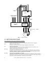
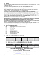
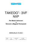
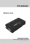
E-POW
INSTRUCTION MANUAL
1
05-09-2013
REV.
DATE
R.T. Check and Approval
CONTENTS
1
FOREWORD .................................................................... ...................Page
3
2
INSTALLATION....................................................................................Page
3
3
CONNECTIONS...................................................................................Page
3
4
OPERATION ........................................................................................Page
5
5
OUTLINE DIMENSIONS AND WEIGHT ..............................................Page
6
DECLARATION OF CONFORMITY.....................................................Page
7
TAKEDO-3VF NXP INSTRUCTION MANUAL (ATTACHED)
2
E-POW
INSTRUCTION MANUAL Release 1 date 05-09-2013
1 – FOREWORD
SMS wishes to thank you for choosing our products.
E-POW is a device that makes it possible to install an inverter operating in closed loop (with encoder) on any
existing system without having to replace the control panel, the gearbox motor, or the electrical system of the
shaft and car.
E-POW complies with European Directives 2004/108/EC and 95/16EC.
IMPORTANT
Included in E-POW there are an inverter of the very latest generation and the interface board for
connection with control panel. They both contain a specific lift application software, which includes
motor thermal protection.
2 – INSTALLATION
E-POW is supplied equipped with the following cables which are already connected to the relative terminals:
• one cable for connection of the device power supply to the A.C. mains.
• one shielded cable for connection of the device output to the panel.
• the shielded cables required for connection of the adaptation circuit board to the panel.
A further 8 meter length of shielded cable is supplied for the connection between control panel and motor.
E-POW is prearranged to be used in 2-speed motor existing lift systems, so that the existing shaft
accessories (switches and magnets) are maintained, without any change to the wirings.
However, you need to modify the spaces, taking into consideration that the inverter default values are
appropriated for slowing-down and stop distances as shown in the concerning TABLES in the inverter
TAKEDO 3VF NXS/P Instruction Manual.
IMPORTANT :
A free service is available: if the customer supplies, while ordering E-POW, the
circuit diagram of the control panel in which the device is to be installed, SMS
indicates on this diagram all the modifications required for a correct application.
3 – CONNECTIONS
CAUTION!
Before making the connections bring the car to an intermediate floor and disconnect all the
power circuits.
IMPORTANT :
E-POW is prearranged for connection to panels with control voltage between 48Vdc
and 120Vdc. If the control voltage is outside this range or AC, ensure you make a
specific request for your application at the time of the order.
3.1 POWER CIRCUIT
The power connection of E-POW must be made up line of the power contactors: always check to ensure
that the operation transformer supply is taken up line from E-POW.
- Connect the three-phase power supply to the input cable (3 Core + Earth, unshielded), which is
connected to terminals L1, L2, L3.
- Connect the output cable (3 Core + Earth, shielded, connected to drive terminals U, V, W) to the panel
contactors.
IMPORTANT
The connection between contactors and motor (i.e. between control panel and motor) must be made
using the shielded cable (3-core + Earth) supplied with the equipment.
The cable shield must be connected to earth at both ends.
-
Bond the earth conductors and the shield to the control panel earth and to the gearbox earth.
CAUTION!
When E-POW is connected, problems are created with type AC 30mA residual current devices. When
installing an inverter drive, to avoid nuisance tripping of the residual current circuit breaker and ensure
effective protection in compliance with regulations, proceed as follows:
- Make sure the building has an efficient earth circuit.
- Install type B residual current devices rated 300mA.
- Wire and bond earth connections efficiently (refer to the inverter drive manual).
3.2 ENCODER CONNECTION
Connect the encoder through the shielded cable it is equipped with, directly to the Encoder Board type
NXOPTA5 installed inside the drive, following the hints existing on the TAKEDO 3VF NXP Manual.
E-POW
INSTRUCTION MANUAL Release 1 date 05-09-2013
3
INPUT
CABLE
L1 L2 L3
E-POW
THREE-PHASE MAINS
3-POLE + EARTH
U V W
OUTPUT
CABLE
CONTROL
PANEL
CONTACTORS
CIRCUIT
CONTROL PANEL – MOTOR
CABLE
M
3 ~
Fig. 1 :
Power connection
3.3 ADAPTATION CIRCUIT BOARD
List of conductors to connect to the adaptation circuit board:
QC1
Board power supply
Connect to the point of the safety chain at which the contactor circuit is supplied.
QC2
Board power supply common.
Connect the common of the control voltage feeding the contactor circuit.
CF1
Slow Speed Command.
Connect directly to the low speed contactor, or connect between CF and CF1 a “free
voltage” normally open contact of the same contactor.
QU, QUA
Command for the upward run contactor.
Interrupt the connection between the up command of the control panel and the coil of the
upward run contactor. Then connect the wire from the control panel command to terminal
QU and the coil of the upward run contactor to terminal QUA.
QD, QDA
Command for the downward run contactor.
Interrupt the connection between the down command of the control panel and the coil of the
downward run contactor. Then connect the wire from the control panel command to terminal
QD and the coil of the downward run contactor to terminal QDA.
4
E-POW
INSTRUCTION MANUAL Release 1 date 05-09-2013
QP+, QP-
Start permit.
Connect respectively to the positive and negative poles of the operation circuit, down line of
the safety chain contacts.
IM
Command for operation in inspection mode.
Connect in such a way that, when the inspection service is enabled by means of the specific
control station on the car roof, a contact closes between CF and IM. This is to assure the
proper working sequence and the car run in medium speed (< 0,63 m/sec).
CAUTION!
In the event of uncertainty, please consult SMS for advice about the correct connection of the
adaptation board.
3.4 BRAKE CONTROL
E-POW features internal contactor TF to control the BRAKE: the TAKEDO 3VF NXP drive manages the
brake control logic directly so that the relative contactor opens only in conditions of safety (motor supplied
with power, with current balanced on all three phases) and closes when the motor stops as the car reaches a
floor.
Contactor TF is wired by SMS; the two conductors TFL2 – TFL3 must be connected in series with the brake
coil power supply.
BRAKE POWER
SUPPLY
TFL2
TFL3
BRAKE
Fig. 2: Connection of the brake control contactor
3.5 FURTHER NOTES ABOUT THE APPLICATION
1. E-POW operates in closed loop, so, to assure the encoder right operation, it is essential that the run
direction is managed by the drive, which has to control and reverse the motor phases.
In the existing control panel you need to modify the power circuit, in order that the up / down contactors
don’t reverse the motor phases.
2. E-POW controls the High Speed winding of the motor: disconnect the Low Speed winding.
3. Make sure that the door opening command for the automatic doors (if any) is enabled after the contactor
de-energization (controlled by E-POW).
4. Make sure that the Retiring Cam (if any) unlocks the door after the contactor de-energization.
4 – OPERATION
When it receives an up or down run command from the control panel, E-POW activates the contactors and,
via the inverter drive, causes the car to move.
If the SW1 switch is set to RUN and the CF1 command is OFF, the movement is performed at high speed;
when the CF1 command from the control panel turns ON, the low speed level is set and the car decelerates.
When the car reaches the floor level, CF1 and QU/QD are disabled: the drive stops the motor electrically and
afterwards E-POW controls the brake deactivation and then contactors deactivation.
There isn’t any MAXIMUM RUN TIME, neither in high speed nor in low speed, in order to avoid ill-timed
action of these protections in case of last long runs or long distances covered in low speed, for instance
during set-up (these controls are usually already included into the most recent control panels).
If the SW1 switch is set to MAN, the car moves in the selected direction at the inspection speed, as long as
the control panel command or the up/down command from the board push-buttons remains active: when the
command breaks off, the car stop instantly, with the brake release.
During all operations, E-POW controls the brake contactor TF. When the drive detects an alarm situation, the
brake is released instantly.
E-POW
INSTRUCTION MANUAL Release 1 date 05-09-2013
5
4.1 SETUP
After having made the CONNECTIONS, open the cover of E-POW and close the main power switch, keeping
the operation valve open.
The first task is to enter the motor data in the drive in the “BASIC PARAMETERS” group.
Instructions on how to edit parameters are provided in the attached TAKEDO 3VF NXS/P Manual.
The green IOK led must illuminate on the circuit board; the green MR led flashes.
Check that switch SW1 is set to RUN and close the operation valve.
Make a call for an upper floor, checking that the motor rotates in the correct direction. If the motor turns in
the wrong direction, invert two of the conductors in the motor terminal box.
Then check if the encoder rotation direction is right (see TAKEDO 3VF NXP Instruction Manual).
Once you have checked the correct rotation directions, return the car to an intermediate floor. Make another
call: the following Led will illuminate on the board: QU/QD, QUA/QDA, QP (if not already lit), RUN and TF.
The deceleration and stopping sequence is as follows: in the slowing-down zone the led CF lights on, the car
decelerates and arrives at the floor. Led CF and QU/QD switch off and then the following leds switch off in
sequence (with a short delay from one to the next): TF, RUN, QUA/QDA and QP.
Setting the SW1 switch to MAN; led IM should illuminate. In this condition E-POW controls the motor in up or
down direction by pressing one of the buttons on the circuit board.
IMPORTANT
The push-buttons on the circuit board which control car movement when switch SW1 is set to MAN,
only operate if Led QP is illuminated, i.e. only if the safety chain contacts are closed.
Once the operations described above have been concluded successfully, operation of the installation can be
optimized. Acceleration, deceleration, and final deceleration can all be adjusted.
To reduce installation times it is good practice to make the adjustments on just one floor, performing up and
down runs until obtaining satisfactory stopping performance. The magnets for the other floors must be
identical and positioned in the same place, perfectly centred with respect to the floor.
4.2 KEY TO SIGNALLING LEDS
MR
IM
IOK
QD
QU
QUA
QDA
CF
QP
RUN
TF
=
=
=
=
=
=
=
=
=
=
=
flashing: indicates the board is working correctly
inspection service
inverter ready
down command
up command
up contactor command
down contactor command
low speed command
safety chain contacts closed
run command for drive
brake contactor command
5 – OUTLINE DIMENSIONS AND WEIGHT
SIZE (kW)
Width (mm)
Height (mm)
Depth (mm)
Weight (kg)
(approximate)
5,5 – 7,5 – 11
(*1)
300
615
240
17
15 – 18,5 – 22
(*2)
300
615
260
36
(*1)
(*2)
For sizes 7,5 – 11kW, N° 1 EXTERNAL Braking Resistor (50Ω 1500W)
For sizes 15 – 18,5kW, N° 2 EXTERNAL Braking Resistors (50Ω 1500W)
For size 22kW,
N° 3 EXTERNAL Braking Resistors (50Ω 1500W)
BRAKING RESISTOR
50Ω
Ω 1500W
Width (mm)
Height (mm)
Depth (mm)
Weight (kg)
480
110
140
2
(approximate)
For further information and advice contact:
SMS SISTEMI e MICROSISTEMI s.r.l. (Gruppo SASSI HOLDING)
Cap. Soc. 260.000 i.v.
Via Guido Rossa, 46/48/50 40056 Crespellano BO
R.E.A 272354 CF - Reg. Imprese Bo 03190050371 P.IVA IT 00601981202
Tel. : +39 051 969037 Fax : +39 051 969303 Technical Service: +39 051 6720710
Web : www.sms.bo.it E-mail : [email protected]
6
E-POW
INSTRUCTION MANUAL Release 1 date 05-09-2013
DECLARATION OF CONFORMITY
Manufacturer: SMS SISTEMI E MICROSISTEMI s.r.l.
Address:
Via Guido Rossa, 46/48/50 – 40056 Crespellano (BO)
Product:
E–POW (equipped with VACON NXP inverter drive)
The above product complies with the following EUROPEAN DIRECTIVES:
95/16/EC
LIFTS
2004/108/EC
ELECTROMAGNETIC COMPATIBILITY
when installed as prescribed by the relative user manual.
To evaluate the product's compliance, reference was made to the following STANDARDS:
UNI EN 81.1: 2010
EN 12015: 2005
EN 12016: 2008
DATE: 21-12-2012
SMS Sistemi e Microsistemi s.r.l.
____________________________
Ing. VITTORIO MAZZONI
CHIEF EXECUTIVE OFFICER
E-POW
INSTRUCTION MANUAL Release 1 date 05-09-2013
7