1
G-4500 Series User Manual
G-4500 Series
User Manual
Warranty
All products manufactured by ICP DAS are warranted against
defective materials for a period of one year from the date of delivery
to the original purchaser.
Warning
ICP DAS assumes no liability for damages consequent to the
use of this product. ICP DAS reserves the right to change this
manual at any time without notice. The information furnished by ICP
DAS is believed to be accurate and reliable. However, no
responsibility is assumed by ICP DAS for its use, or for any
infringements of patents or other rights of third parties resulting from
its use.
Copyright
Copyright 2008 by ICP DAS Co., LTD. All rights reserved
worldwide.
Trademark
The names used for identification only may be registered
trademarks of their respective companies.
1
Publication August, 2013 Ver. 1.15
G-4500 Series User Manual
Tables of Content
Chapter 1 Introduction .................................................... 5
Chapter 2 Hardware specifications ................................ 6
2.1 G-4500 Hardware ...................................................................... 6
2.1.1 G-4500-SIM300 Series .................................................................... 6
2.1.2 G-4500-SIM340 Series .................................................................... 7
2.1.3 GD-4500-SIM340 Series ................................................................. 8
2.1.4 G-4500-2G Series ............................................................................ 9
2.2 G-4500 specifications ........................................................... 10
2.2.1 G-4500-SIM300 Specifications ................................................... 10
2.2.2 G-4500-SIM340 Specifications ................................................... 13
2.2.3 GD-4500-SIM340 Specifications ................................................ 16
2.2.4 G-4500-2G Specifications ........................................................... 19
Chapter 3 Application architecture .............................. 22
3.1 Car Monitor System ............................................................... 23
3.2 Remote Control/Monitor System ....................................... 24
3.3 GIS system ............................................................................... 25
3.4 Redundance Communication system .............................. 26
Chapter 4 Hardware Appearance ................................. 27
4.1 Pin Assignments .................................................................... 27
4.2 Hardward Dimensions .......................................................... 28
4.3 Operation Mode Switch ........................................................ 31
4.4 LED indicators ........................................................................ 32
Chapter 5 Hardware Wire Connection ......................... 33
5.1 Wire Connection ..................................................................... 33
5.2 GPRS/GSM Installation ......................................................... 35
5.3 GPS Installation ...................................................................... 36
Chapter 6 Function Introduction .................................. 37
6.1 IO Library Function Definition and Description ............ 37
6.1.1 X305IO_Init ...................................................................................... 38
6.1.2 X305IO_GetLibVersion ................................................................. 39
6.1.3 X305IO_Read_AD_CalibrationGain .......................................... 40
2
Publication August, 2013 Ver. 1.15
G-4500 Series User Manual
6.1.4 X305IO_Read_AD_CalibrationOffset ....................................... 41
6.1.5 X305IO_AnalogIn ........................................................................... 42
6.1.6 X305IO_Read_All_DI..................................................................... 43
6.1.7 X305IO_Read_One_DI .................................................................. 44
6.1.8 X305IO_Write_All_DO .................................................................. 45
6.1.9 X305IO_Write_One_DO ................................................................ 46
6.1.10 X305IO_Read_All_DO ................................................................ 47
6.1.11 X305IO_Read_One_DO .............................................................. 48
6.1.12 X305IO_AnalogIn_SetChannel ................................................ 49
6.1.13 X305IO_AnalogIn_Hex ............................................................... 50
6.1.14 X305IO_AnalogIn_HexToFloat ................................................. 51
6.2 MMC/SD Library Function Definition and Description 52
6.2.1 PC_Ertfs_Init................................................................................... 53
6.2.2 PC_Open.......................................................................................... 54
6.2.3 PC_Read .......................................................................................... 56
6.2.4 PC_Write .......................................................................................... 57
6.2.5 PC_Close ......................................................................................... 58
6.2.6 Get_ErrNo........................................................................................ 59
6.2.7 PC_lseek .......................................................................................... 60
6.2.8 PC_MKDir ........................................................................................ 61
6.2.9 PC_RMDir ........................................................................................ 62
6.2.10 PC_deltree..................................................................................... 63
6.2.11 PC_MV ............................................................................................ 64
6.2.12 PC_IsDir ......................................................................................... 65
6.2.13 PC_Pwd ......................................................................................... 66
6.2.14 PC_Get_Attributes ...................................................................... 67
6.2.15 PC_Set_Attributes ...................................................................... 69
6.3 LCD Library Function Definition and Description ........ 70
6.3.1 LCD_Init ........................................................................................... 71
6.3.2 LCD_BackLight_On ...................................................................... 72
6.3.3 LCD_BackLight_Off ...................................................................... 73
6.3.4 LCD_ShowText............................................................................... 74
6.3.5 LCD_DisplayNumber .................................................................... 75
6.3.6 LCD_SetNumber ............................................................................ 76
6.3.7 LCD_ClrNumber............................................................................. 77
6.3.8 LCD_ClrScrn ................................................................................... 78
6.3.9 LCD_StandByMode ....................................................................... 79
6.3.10 LCD_NormalMode ....................................................................... 80
6.3.11 LCD_GotoPosition ...................................................................... 81
3
Publication August, 2013 Ver. 1.15
G-4500 Series User Manual
6.3.12 LCD_CursorDisplay.................................................................... 82
6.3.13 LCD_LineReverse ....................................................................... 83
6.3.14 LCD_LineRestore ........................................................................ 84
6.3.15 LCD_GetLibDate .......................................................................... 85
6.3.16 LCD_GetLibVersion .................................................................... 86
Chapter 7 Program Download Procedure ................... 87
4
Publication August, 2013 Ver. 1.15
G-4500 Series User Manual
Chapter 1 Introduction
The G-4500 series provided by ICP DAS are M2M (Machine to Machine) embedded
controller with a cellular transceiver can monitoring industrial equipment that sends live
data to the monitoring system, providing real-time status. With optional GPS model, the
G-4500 can also be a GPS tracking system. It can be used in vehicle management system
or maritime system.
Within the high performance CPU, the G-4500 series can handle a large of data and are
suit for the hard industrial environment. The G-4500 series feature GPRS/GSM module,
Ethernet interface, optional GPS module, 3 digital inputs, 3 digital outputs, 8 analog inputs,
2 RS-232 and 1 RS-485 port. That can be used in various application fields to transfer data
by GPRS, SMS, Ethernet or serial bus. In traditional application, users need a master
controller to integrate a GPRS/GSM modem with developing GPRS or SMS programs into
the host. That would waste much time to integrate the various communication interfaces.
Now, we have G-4500 series to solve the hardware integration problems with easy-to-used
libraries. The G-4500 series built-in MiniOS7 provide the same development environment
with I-7188/I-7186 series. It is more easy for I-7188/I-7186 users to apply the G-4500
series.
Using G-4500 M2M communications, a machine can be installed virtually anywhere but
still be connected to a support centre to signal performance or need for service. M2M data
will improve the service quality and reduce operating costs. Many application areas can be
improved using G-4500.
The G-4500 series applications can be divided into 2 parts: One part is the fixed
intelligent remote management equipment such as water monitor system, vending machine
system, remote machine monitor, home security, POS system, power measurement system
and etc. Another kind of application is movement management equipment such as vehicle
management system, maritime system, taxi dispatch system, and etc. Anyway, the G-4500
can save the cost and development time for users.
5
Publication August, 2013 Ver. 1.15
G-4500 Series User Manual
Chapter 2 Hardware specifications
2.1 G-4500 Hardware
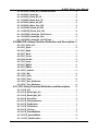
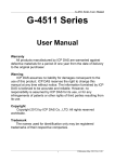
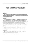
2.1.1 G-4500-SIM300 Series
G-4500-SIM300
G-4500D-SIM300
G-4500P-SIM300
6
G-4500PD-SIM300
Publication August, 2013 Ver. 1.15
G-4500 Series User Manual
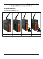
2.1.2 G-4500-SIM340 Series
G-4500-SIM340
G-4500D-SIM340
G-4500P-SIM340
7
G-4500PD-SIM340
Publication August, 2013 Ver. 1.15
G-4500 Series User Manual
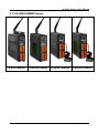
2.1.3 GD-4500-SIM340 Series
GD-4500-SIM340
GD-4500D-SIM340
GD-4500P-SIM340
8
GD-4500PD-SIM340
Publication August, 2013 Ver. 1.15
G-4500 Series User Manual
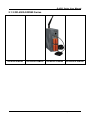
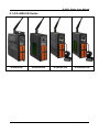
2.1.4 G-4500-2G Series
G-4500-2G
G-4500D-2G
G-4500P-2G
9
G-4500PD-2G
Publication August, 2013 Ver. 1.15
G-4500 Series User Manual
2.2 G-4500 specifications
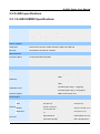
2.2.1 G-4500-SIM300 Specifications
G-4500-SIM300
Item
G-4500D-SIM300
G-4500P-SIM300
CPU
80 MHz internal microprocessor
SRAM/Flash
512K/512K , real time clock, watchdog timer
NVRAM
31 bytes, battery backup, data valid up to 10 years
EEPROM
16 KB, retention > 40 years. 1,000,000 erase/write cycles
G-4500PD-SIM300
Comm. Interface
COM ports
COM1:5-wire RS-232; COM2: RS-485; COM3:3-wire RS-232
Ethernet
10/100 Base-TX Ethernet controller
GPRS Interface
Frequency Band
Tri-band 900/1800/1900 MHz
GPRS connectivity
GPRS class 10/8; GPRS station class B
SMS
MT, MO, CB, Text and PDU mode
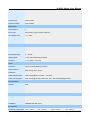
GPS Interface
Support Channels
-
32
Tracking = up to -159 dBm (with external
LNA)
Sensitivity
Cold start = up to -146 dBm (with external
LNA)
Hot start (Open Sky) = 2 s(typical)
Acquisition Time
Cold start (Open Sky) = 36 s(typical)
Protocol Support
-
NMEA 0183 version 3.01
LCD Interface
Effective display
area
-
General
Module
Dimension
Life Time
80.61 mm x 14.37
mm (W x H)
-
93 mm x 70 mm x
-
1.6 mm (W x H x
-
T)
-
Expected life is
more than 100,000
10
-
80.61 mm x 14.37
mm (W x H)
93 mm x 70 mm x 1.6
mm (W x H x T)
Expected life is more
than 100,000 hours
Publication August, 2013 Ver. 1.15
G-4500 Series User Manual
hours under
under normal
normal operation
operation
Digital Output
Output Channel
3
Output Type
Open Collector (Sink/NPN)
Load Voltage
+30 VDC max.
Load Current
100 mA max.
Isolated Voltage
Non-isolated
Digital Input
Input Channel
3
Input Type
Source(Dry Type), Common Ground
Off Voltage Level
+1 V max.
On Voltage Level
+3.5 ~ +30 V
Isolated Voltage
Non-isolated
Analog Input
Input Channel
8
Resolution
12 - bit
Input Range/Type
0 ~ 20 mA
Sample Rate
1 KHz max. (Read one channel)
Accuracy
+/- 2 LSB (+/- 0.01 mA)
Power
Protection
Power reverse polarity protection
Frame Ground Protection ESD, Surge, EFT, Hi-Pot
Power Requirement
15W; Unregulated +10 VDC ~ +30 VDC
Power Consumption
Idle: 75 mA @ 24 VDC; Data Link: 150 ~ 400 mA (peak) @ 24 VDC
LED Indicators
System
Red
GPRS
Yellow
GPS
Green
Yes
Mechanical
Casing
Metal
Dimensions
47 mm x 142 mm x 168 mm (W x L x H)
Installation
DIN-Rall and wall mount
11
Publication August, 2013 Ver. 1.15
G-4500 Series User Manual
Environment
Operating Temperature
-20 ~ +70 °C
-15 ~ +55 °C
-20 ~ +70 °C
-15 ~ +55 °C
Storage Temperature
-40 ~ +80 °C
-20 ~ +70 °C
-40 ~ +80 °C
-20 ~ +70 °C
Humidity
5~90% RH, non-condensing
12
Publication August, 2013 Ver. 1.15
G-4500 Series User Manual
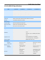
2.2.2 G-4500-SIM340 Specifications
G-4500-SIM340
Item
G-4500D-SIM340
G-4500P-SIM340
CPU
80 MHz internal microprocessor
SRAM/Flash
512K/512K , real time clock, watchdog timer
NVRAM
31 bytes, battery backup, data valid up to 10 years
EEPROM
16 KB, retention > 40 years. 1,000,000 erase/write cycles
G-4500PD-SIM340
Comm. Interface
COM ports
COM1:5-wire RS-232; COM2: RS-485; COM3:3-wire RS-232
Ethernet
10/100 Base-TX Ethernet controller
GPRS Interface
Frequency Band
Quad-band 850/900/1800/1900 MHz
GPRS connectivity
GPRS class 10/8; GPRS station class B
SMS
MT, MO, CB, Text and PDU mode
GPS Interface
Support Channels
-
32
Tracking = up to -159 dBm (with external
LNA)
Sensitivity
Cold start = up to -146 dBm (with external
LNA)
Hot start (Open Sky) = 2 s(typical)
Acquisition Time
Cold start (Open Sky) = 36 s(typical)
Protocol Support
-
NMEA 0183 version 3.01
LCD Interface
Effective
display area
-
General
Module
Dimension
80.61 mm x 14.37
mm (W x H)
-
93 mm x 70 mm x
-
1.6 mm (W x H x
-
T)
Expected life is
Life Time
-
more than
100,000 hours
under normal
13
80.61 mm x 14.37 mm
(W x H)
93 mm x 70 mm x 1.6
mm (W x H x T)
Expected life is more
-
than 100,000 hours
under normal
operation
Publication August, 2013 Ver. 1.15
G-4500 Series User Manual
operation
Digital Output
Output Channel
3
Output Type
Open Collector (Sink/NPN)
Load Voltage
+30 VDC max.
Load Current
100 mA max.
Isolated Voltage
Non-isolated
Digital Input
Input Channel
3
Input Type
Source(Dry Type), Common Ground
Off Voltage Level
+1 V max.
On Voltage Level
+3.5 ~ +30 V
Isolated Voltage
Non-isolated
Analog Input
Input Channel
8
Resolution
12 - bit
Input Range/Type
0 ~ 20 mA
Sample Rate
1 KHz max. (Read one channel)
Accuracy
+/- 2 LSB (+/- 0.01 mA)
Power
Protection
Power reverse polarity protection
Frame Ground Protection ESD, Surge, EFT, Hi-Pot
Power Requirement
15W; Unregulated +10 VDC ~ +30 VDC
Power Consumption
Idle: 75 mA @ 24 VDC; Data Link: 150 ~ 400 mA (peak) @ 24 VDC
LED Indicators
System
Red
GPRS
Yellow
GPS
Green
Yes
Mechanical
Casing
Metal
Dimensions
47 mm x 142 mm x 168 mm (W x L x H)
Installation
DIN-Rall and wall mount
14
Publication August, 2013 Ver. 1.15
G-4500 Series User Manual
Environment
Operating Temperature
-20 ~ +70 °C
-15 ~ +55 °C
-20 ~ +70 °C
-15 ~ +55 °C
Storage Temperature
-40 ~ +80 °C
-20 ~ +70 °C
-40 ~ +80 °C
-20 ~ +70 °C
Humidity
5~90% RH, non-condensing
15
Publication August, 2013 Ver. 1.15
G-4500 Series User Manual
2.2.3 GD-4500-SIM340 Specifications
Item
GD-4500-SIM340 GD-4500D-SIM340 GD-4500P-SIM340
CPU
80 MHz internal microprocessor
SRAM/Flash
512K/512K , real time clock, watchdog timer
NVRAM
31 bytes, battery backup, data valid up to 10 years
EEPROM
16 KB, retention > 40 years. 1,000,000 erase/write cycles
GD-4500PD-SIM340
Comm. Interface
COM ports
COM1:5-wire RS-232; COM2: RS-485; COM3:3-wire RS-232
Ethernet
10/100 Base-TX Ethernet controller
GPRS Interface
Frequency Band
Quad-band 850/900/1800/1900 MHz
GPRS connectivity
GPRS class 10/8; GPRS station class B
SMS
MT, MO, CB, Text and PDU mode
GPS Interface
Support Channels
-
32
Tracking = up to -159 dBm (with external
LNA)
Sensitivity
Cold start = up to -146 dBm (with external
LNA)
Hot start (Open Sky) = 2 s(typical)
Acquisition Time
Cold start (Open Sky) = 36 s(typical)
Protocol Support
-
NMEA 0183 version 3.01
LCD Interface
Effective
display area
-
80.61 mm x 14.37
mm (W x H)
-
80.61 mm x 14.37 mm
(W x H)
General
Module
Dimension
-
93 mm x 70 mm x
1.6 mm (W x H x T)
-
Expected life is
Life Time
-
more than 100,000
hours under
normal operation
93 mm x 70 mm x 1.6
mm (W x H x T)
Expected life is more
-
than 100,000 hours
under normal operation
Digital Output
16
Publication August, 2013 Ver. 1.15
G-4500 Series User Manual
Output Channel
3
Output Type
Open Collector (Sink/NPN)
Load Voltage
+30 VDC max.
Load Current
100 mA max.
Isolated Voltage
Non-isolated
Digital Input
Input Channel
3
Input Type
Source(Dry Type), Common Ground
Off Voltage Level
+1 V max.
On Voltage Level
+3.5 ~ +30 V
Isolated Voltage
Non-isolated
Analog Input
Input Channel
8
Resolution
12 - bit
Input Range/Type
0 ~ 20 mA
Sample Rate
1 KHz max. (Read one channel)
Accuracy
+/- 2 LSB (+/- 0.01 mA)
Power
Protection
Frame Ground
Protection
Power reverse polarity protection
ESD, Surge, EFT, Hi-Pot
Power Requirement
15W; Unregulated +10 VDC ~ +30 VDC
Power Consumption
Idle: 75 mA @ 24 VDC; Data Link: 150 ~ 400 mA (peak) @ 24 VDC
LED Indicators
System
Red
GPRS
Yellow
GPS
Green
Yes
Mechanical
Casing
Plastic
Dimensions
60 mm x 140 mm x 172 mm (W x L x H)
Installation
DIN-Rall and wall mount
Environment
Operating Temperature -20 ~ +70 °C
-15 ~ +55 °C
17
-20 ~ +70 °C
-15 ~ +55 °C
Publication August, 2013 Ver. 1.15
G-4500 Series User Manual
Storage Temperature
-40 ~ +80 °C
-20 ~ +70 °C
Humidity
5~90% RH, non-condensing
18
-40 ~ +80 °C
-20 ~ +70 °C
Publication August, 2013 Ver. 1.15
G-4500 Series User Manual
2.2.4 G-4500-2G Specifications
G-4500-2G
Item
G-4500D-2G
G-4500P-2G
CPU
80 MHz internal microprocessor
SRAM/Flash
512K/512K , real time clock, watchdog timer
NVRAM
31 bytes, battery backup, data valid up to 10 years
EEPROM
16 KB, retention > 40 years. 1,000,000 erase/write cycles
G-4500PD-2G
Comm. Interface
COM ports
COM1:5-wire RS-232; COM2: RS-485; COM3:3-wire RS-232
Ethernet
10/100 Base-TX Ethernet controller
GPRS Interface
Frequency Band
Quad-band 850/900/1800/1900 MHz
GPRS connectivity
GPRS class 10/8; GPRS station class B
SMS
MT, MO, CB, Text and PDU mode
GPS Interface
Support Channels
-
32
Tracking = up to -159 dBm (with external
LNA)
Sensitivity
Cold start = up to -146 dBm (with external
LNA)
Hot start (Open Sky) = 2 s(typical)
Acquisition Time
Cold start (Open Sky) = 36 s(typical)
Protocol Support
-
NMEA 0183 version 3.01
LCD Interface
Effective
display area
-
General
Module
Dimension
80.61 mm x 14.37
mm (W x H)
-
93 mm x 70 mm x
-
1.6 mm (W x H x
-
T)
Expected life is
Life Time
-
more than
100,000 hours
under normal
19
80.61 mm x 14.37 mm
(W x H)
93 mm x 70 mm x 1.6
mm (W x H x T)
Expected life is more
-
than 100,000 hours
under normal
operation
Publication August, 2013 Ver. 1.15
G-4500 Series User Manual
operation
Digital Output
Output Channel
3
Output Type
Open Collector (Sink/NPN)
Load Voltage
+30 VDC max.
Load Current
100 mA max.
Isolated Voltage
Non-isolated
Digital Input
Input Channel
3
Input Type
Source(Dry Type), Common Ground
Off Voltage Level
+1 V max.
On Voltage Level
+3.5 ~ +30 V
Isolated Voltage
Non-isolated
Analog Input
Input Channel
8
Resolution
12 - bit
Input Range/Type
0 ~ 20 mA
Sample Rate
1 KHz max. (Read one channel)
Accuracy
+/- 2 LSB (+/- 0.01 mA)
Power
Protection
Power reverse polarity protection
Frame Ground Protection ESD, Surge, EFT, Hi-Pot
Power Requirement
15W; Unregulated +10 VDC ~ +30 VDC
Power Consumption
Idle: 75 mA @ 24 VDC; Data Link: 150 ~ 400 mA (peak) @ 24 VDC
LED Indicators
System
Red
GPRS
Yellow
GPS
Green
Yes
Mechanical
Casing
Metal
Dimensions
47 mm x 142 mm x 168 mm (W x L x H)
Installation
DIN-Rall and wall mount
20
Publication August, 2013 Ver. 1.15
G-4500 Series User Manual
Environment
Operating Temperature
-20 ~ +70 °C
-15 ~ +55 °C
-20 ~ +70 °C
-15 ~ +55 °C
Storage Temperature
-40 ~ +80 °C
-20 ~ +70 °C
-40 ~ +80 °C
-20 ~ +70 °C
Humidity
5~90% RH, non-condensing
21
Publication August, 2013 Ver. 1.15
G-4500 Series User Manual
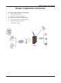
Chapter 3 Application architecture
On motion type equipment application
Motorcade management
The police usage the equipment.
On stationary equipment application
Remote POS (Point Of Sale) terminals
Automatically trading machine
Water quality monitor
22
Publication August, 2013 Ver. 1.15
G-4500 Series User Manual
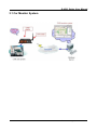
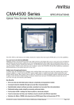
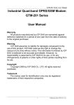
3.1 Car Monitor System
23
Publication August, 2013 Ver. 1.15
G-4500 Series User Manual
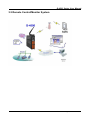
3.2 Remote Control/Monitor System
24
Publication August, 2013 Ver. 1.15
G-4500 Series User Manual
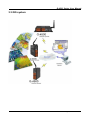
3.3 GIS system
25
Publication August, 2013 Ver. 1.15
G-4500 Series User Manual
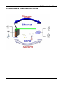
3.4 Redundance Communication system
26
Publication August, 2013 Ver. 1.15
G-4500 Series User Manual
Chapter 4 Hardware Appearance
4.1 Pin Assignments
27
Publication August, 2013 Ver. 1.15
G-4500 Series User Manual
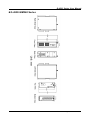
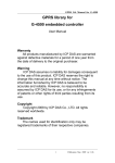
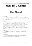
4.2 Hardward Dimensions
G-4500-SIM300 Series
28
Publication August, 2013 Ver. 1.15
G-4500 Series User Manual
G-4500-SIM340 Series
29
Publication August, 2013 Ver. 1.15
G-4500 Series User Manual
GD-4500 Series
30
Publication August, 2013 Ver. 1.15
G-4500 Series User Manual
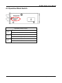
4.3 Operation Mode Switch
Operation Mode Switch
RUN
Lock
INIT
OS can execute autoexec.bat
Flash can be read/wirte.
OS can execute autoexec.bat
Flash is read only (lock).
OS can not execute autoexec.bat
Flash can be read/wirte.
31
Publication August, 2013 Ver. 1.15
G-4500 Series User Manual
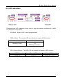
4.4 LED indicators
There are three LED indicators to help users to judge the various conditions of G-4500.
The description is as follows:
SYS(Red):System LED is users programmable.
GSM (Yellow):The modem LED can indicate the status of GSM module.
Modem normal
Blanking (3 sec)
Modem fail
Off
or
Blanking (not 3 sec)
GPS (Green)(Option):The GPS LED can indicate the status of GPS module.
GPS Fail
Search GPS
Receive GPS data
Always off
Always on
Blanking (1 sec)
32
Publication August, 2013 Ver. 1.15
G-4500 Series User Manual
Chapter 5 Hardware Wire Connection
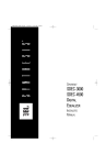
5.1 Wire Connection
Digital Input Wire Connection
Input Type
ON State
OFF State
DI value as 0
DI value as 1
Relay Contact
TTL/CMOS Logic
Open Collector
Digital Output Wire Connection
Input Type
ON State
OFF State
DO value as 1
DO value as 0
Drive Relay
Resistance Load
33
Publication August, 2013 Ver. 1.15
G-4500 Series User Manual
Current Input Wire Connection
Input Type
34
Publication August, 2013 Ver. 1.15
G-4500 Series User Manual
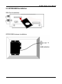
5.2 GPRS/GSM Installation
SIM Card Installation
GPRS/GSM Antenna Installation
35
Publication August, 2013 Ver. 1.15
G-4500 Series User Manual
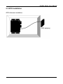
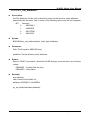
5.3 GPS Installation
GPS Antenna Installation
36
Publication August, 2013 Ver. 1.15
G-4500 Series User Manual
Chapter 6 Function Introduction
6.1 IO Library Function Definition and Description
Function definition
Description
X305IO_Init
Initial I/O
X305IO_GetLibVersion
Get X305IO_LIB Version
X305IO_Read_AD_CalibrationGain
Read AD Calibration Gain
X305IO_Read_AD_CalibrationOffset
Read AD Calibration Offset
X305IO_AnalogIn
Read value from assign AI
channel
X305IO_Read_All_DI
Read All DI
X305IO_Read_One_DI
Read the value form assign
DI channel
X305IO_Write_All_DO
Write All DO
X305IO_Write_One_DO
Write the value to the assign
DO channel
X305IO_Read_All_DO
Read All DO state
X305IO_Read_One_DO
Read the DO state form the
assign DO channel.
Set the AI channel that users
want to read.
Read the value from the
specific A/D channel (12 bits)
Transfer the AI value from 12
bits to float
X305IO_AnalogIn_SetChannel
X305IO_AnalogIn_Hex
X305IO_AnalogIn_HexToFloat
37
Publication August, 2013 Ver. 1.15
G-4500 Series User Manual
6.1.1 X305IO_Init
Description:
Initial X305IO.
Syntax:
int X305IO_Init(void)
Parameter:
None
Return:
Return value: 0
<>0
==> success
==> error
38
Publication August, 2013 Ver. 1.15
G-4500 Series User Manual
6.1.2 X305IO_GetLibVersion
Description:
Get X305IO_Lib Version.
Syntax:
unsigned X305IO_GetLibVersion(void)
Parameter:
None
Return:
Version Number
39
Publication August, 2013 Ver. 1.15
G-4500 Series User Manual
6.1.3 X305IO_Read_AD_CalibrationGain
Description:
Read the A/D Calibration Gain.
Syntax:
float X305IO_Read_AD_CalibrationGain(void)
Parameter:
None
Return:
Calibration Gain of the AD channels
40
Publication August, 2013 Ver. 1.15
G-4500 Series User Manual
6.1.4 X305IO_Read_AD_CalibrationOffset
Description:
Read the A/D Calibration Offset.
Syntax:
float X305IO_Read_AD_CalibrationOffset (void)
Parameter:
None
Return:
Calibration Offset of the AD channels
41
Publication August, 2013 Ver. 1.15
G-4500 Series User Manual
6.1.5 X305IO_AnalogIn
Description:
Read the value from the assign AI channel.
Syntax:
float X305IO_AnalogIn(int iChannel)
Parameter:
iChannel = 0~7 ----> ch0~ch7
Return:
0.0mA ~ 20.0mA
42
Publication August, 2013 Ver. 1.15
G-4500 Series User Manual
6.1.6 X305IO_Read_All_DI
Description:
Read all DI values of the G-4500.
Syntax:
int X305IO_Read_All_DI(void)
Parameter:
None
Return:
0x00~0x07
Example:
When DI0 Ground
DI1 Open
DI2 Open
value = X305IO_Read_All_DI( );
value=0x6
43
Publication August, 2013 Ver. 1.15
G-4500 Series User Manual
6.1.7 X305IO_Read_One_DI
Description:
Read the value from the assign DI channel.
Syntax:
int X305IO_Read_One_DI(int iChannel)
Parameter:
iChannel = 0~2----> ch0~ch2
Return:
Return 1 => open
Logic high level (+3.5V ~ +30V)
Return 0 => close to GND
Logic low level (0V ~ +1V)
44
Publication August, 2013 Ver. 1.15
G-4500 Series User Manual
6.1.8 X305IO_Write_All_DO
Description:
Write to all DO values of the G-4500 series.
Syntax:
void X305IO_Write_All_DO(int iOutValue)
Parameter:
iOutValue = 0x0~0x7
Return:
None
Example:
X305IO_Write_All_DO(6);
After function execute
DO0 OFF
DO1 ON
DO2 ON
45
Publication August, 2013 Ver. 1.15
G-4500 Series User Manual
6.1.9 X305IO_Write_One_DO
Description:
Write the specific value to the assign DO channel.
Syntax:
void X305IO_Write_One_DO(int iChannel, int iStatus)
Parameter:
iChannel = 0~2----> ch0~ch2
iStatus = 1 => Status is ON
iStatus = 0 => Status is OFF
Return:
None
46
Publication August, 2013 Ver. 1.15
G-4500 Series User Manual
6.1.10 X305IO_Read_All_DO
Description:
Read all DO values of the G-4500 series.
Syntax:
int X305IO_Read_All_DO(void)
Parameter:
None
Return:
0x0~0x7
Example:
When DO0 OFF
DO1 ON
DO2 ON
Value= X305IO_Read_All_DO( );
Value=0x6
47
Publication August, 2013 Ver. 1.15
G-4500 Series User Manual
6.1.11 X305IO_Read_One_DO
Description:
Read the state from the assign DO channel.
Syntax:
int X305IO_Read_One_DO(int iChannel)
Parameter:
iChannel = 0~2----> ch0~ch2
Return:
Return 1 => ON
Return 0 => OFF
48
Publication August, 2013 Ver. 1.15
G-4500 Series User Manual
6.1.12 X305IO_AnalogIn_SetChannel
Description:
Set the specific AI channel that users want to read.
Syntax:
int X305IO_AnalogIn_SetChannel(unsigned iChannel)
Parameter:
iChannel = 0~7----> ch0~ch7
Return:
Return 0 => Set up success
Return -1 => Set iChannel number error
49
Publication August, 2013 Ver. 1.15
G-4500 Series User Manual
6.1.13 X305IO_AnalogIn_Hex
Description:
Read the value of the assign AI channel assigned by X305IO_AnalogIn_SetChannel
function.
Syntax:
int X305IO_AnalogIn_Hex(void)
Parameter:
None
Return:
After Read assign AI channel value.
Example:
X305IO_AnalogIn_SetChannel(0);
X305IO_AnalogIn_Hex( );
// Set channel 0
50
Publication August, 2013 Ver. 1.15
G-4500 Series User Manual
6.1.14 X305IO_AnalogIn_HexToFloat
Description:
Set the AI value from 12 bits to float format.
Syntax:
float X305IO_AnalogIn_HexToFloat(int iValue)
Parameter:
A value want to 12 bits transform float.
Return:
The transferred AI value by float format
Example:
Set the channel 0 to read, and then transform the value to float.
float AdValue;
X305IO_AnalogIn_SetChannel(0);
AdValue=X305IO_AnalogIn_HexToFloat(X305IO_AnalogIn_Hex( ));
51
Publication August, 2013 Ver. 1.15
G-4500 Series User Manual
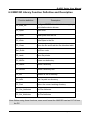
6.2 MMC/SD Library Function Definition and Description
Function definition
Description
PC_Ertfs_Init
Configure ERTFS drive letter/device mapping
and initialize device drivers.
PC_Open
Open a file
PC_Read
Read bytes from the file
PC_Write
Write Bytes to the file
PC_Close
Close the file and flush the file allocation table
Get_ErrNo
Get Error code
PC_lseek
Move file pointer
PC_MKDir
Create a subdirectory
PC_RMDir
Delete a directory
PC_deltree
Delete a directory tree
PC_MV
Rename a file or directory
PC_IsDir
Test if a path is a directory
PC_Pwd
Return the current working directory
PC_Get_Attributes
Get File Attributes
PC_Set_Attributes
Set File Attributes
Note: Before using these functions, users must format the MMC/SD card as FAT16 from
the PC.
52
Publication August, 2013 Ver. 1.15
G-4500 Series User Manual
6.2.1 PC_Ertfs_Init
Description:
Configure ERTFS drive letter/device mapping and initialize device drivers.
Syntax:
BOOLEAN pc_ertfs_init(void)
Parameter:
None
Return:
Return value: True
Fail
==> success
==> no success
53
Publication August, 2013 Ver. 1.15
G-4500 Series User Manual
6.2.2 PC_Open
Description:
Open/Create the file from MMC/SD card with the specific mode.
Syntax:
PCFD pc_open(char *name, word flag, word mode)
Parameter:
Name :
The file path in MMC/SD card
Flag :
PO_APPEND
- Seek to eof on each write.
PO_BINARY
- Ignored. All file access is binary.
PO_TEXT
- Ignored.
PO_RDONLY
- Open for read only
PO_RDWR
- Read/write access allowed.
PO_WRONLY
- Open for write only.
PO_CREAT
- Create the file if it does not exist.
PO_EXCL
- If flag has (PO_CREAT | PO_EXCL) and the file already exists,
fail and set get_errno() to PEEXIST.
PO_TRUNC
- Truncate the file if it already exists.
PO_NOSHAREANY - Fail if the file is already open.
PO_NOSHAREWRITE - Fail if the file is already open for write.
Mode :
PS_IWRITE - Write permitted.
PS_IREAD
- Read permitted. (Always true anyway)
Return:
Returns a non-negative integer to be used as a file descriptor for calling po_read,
po_write, po_lseek, po_flush, po_truncate, and po_close, otherwise it returns -1 and
get_errno.
Example:
54
Publication August, 2013 Ver. 1.15
G-4500 Series User Manual
This example below would show to open test1 file and set the file allowing read or
write.
char *fname="test1\\test1.txt";
pc_ertfs_init();
pc_open(fname,
(word) (PO_BINARY|PO_RDWR|PO_CREAT|PO_APPEND),
(word) (PS_IWRITE | PS_IREAD) );
55
Publication August, 2013 Ver. 1.15
G-4500 Series User Manual
6.2.3 PC_Read
Description:
Read bytes from a file.
Syntax:
int pc_read(PCFD fd, byte *buf, word count)
Parameter:
fd - file desc
*buf
Count
- data buf
- data length
Return:
Returns the actual number of bytes read or Oxffff on error. If the return value is Oxffff,
get_errno will return one of the following :
PEBADF - Invalid file descriptor
PENOSPC - Write failed. Presumably because of no space
Example:
char *fname="test1\\test1.txt";
PCFD out_fd;
char bff[129];
pc_ertfs_init();
out_fd = pc_open(fname,
(word) (PO_BINARY|PO_RDWR|PO_CREAT|PO_APPEND),
(word) (PS_IWRITE | PS_IREAD) );
pc_read(out_fd, bff, 512);
56
Publication August, 2013 Ver. 1.15
G-4500 Series User Manual
6.2.4 PC_Write
Description:
Write Bytes to a file.
Syntax:
int pc_write(PCFD fd, byte *buf, word count)
Parameter:
fd - file desc
*buf
Count
- write data buf
- data length
Return:
Returns the actual number of bytes read or Oxffff on error. If the return value is Oxffff,
get_errno will return one of the following :
PEBADF - Invalid file descriptor
PENOSPC - Write failed. Presumably because of no space
Example:
This example will open test1 file, and set read/write is allowed.And write a data.
char *fname="test1\\test1.txt";
PCFD out_fd;
char bf[129],bff[129];
long testcnt=0;
int len;
pc_ertfs_init();
out_fd = pc_open(fname,
(word) (PO_BINARY|PO_RDWR|PO_CREAT|PO_APPEND),
(word) (PS_IWRITE | PS_IREAD) );
len=sprintf(bf,"Line:%09lu\r\n",testcnt++);
pc_write(out_fd,bf,len);
57
Publication August, 2013 Ver. 1.15
G-4500 Series User Manual
6.2.5 PC_Close
Description:
Close a file.
Syntax:
int pc_close(PCFD fd)
Parameter:
fd - file desc
Return:
Returns 0 if all went well, otherwise -1. If -1 is returned, get_errno will return one of
these values:
PEBADF - Invalid file descriptor
PENOSPC - Write failed. Presumably because of no space
58
Publication August, 2013 Ver. 1.15
G-4500 Series User Manual
6.2.6 Get_ErrNo
Description:
Get error code.
Syntax:
int get_errno(void)
Parameter:
None
Return:
2 ==> PENOENT - File not found or path to file not found.
9 ==> PEBADF
- Invalid file descriptor.
13==> PEACCESS - Attempt to open a read only file or a special (directory).
17 ==> PEEXIST - Exclusive access requested but file already exists.
22 ==> PEINVAL - Seek to negative file pointer attempted.
24 ==> PEMFILE - No file descriptors available (too many files open).
28 ==> PENOSPC - Write failed. Presumably because of no space.
30 ==> PESHARE - Open failed do to sharing.
31 ==> PEDVICE - No Valid Disk Present.
32 ==> PEBADDIR - DELTREE -- Directory structure corrupt.
59
Publication August, 2013 Ver. 1.15
G-4500 Series User Manual
6.2.7 PC_lseek
Description:
Move file pointer.
Syntax:
long pc_lseek(PCFD fd, long offset, int origin)
Parameter:
fd - file desc
offset –offset value
origin:
PSEEK_SET
PSEEK_CUR
PSEEK_END
- offset from begining of file
- offset from current file pointer
- offset from end of file
Return:
If success, Returns new offset value, otherwise -1. If -1 is returned, get_errno will
return one of these values:
PEBADF - Invalid file descriptor
PEINVAL - Seek to negative file pointer attempted
60
Publication August, 2013 Ver. 1.15
G-4500 Series User Manual
6.2.8 PC_MKDir
Description:
Create a subdirectory.
Syntax:
BOOLEAN pc_mkdir(char *name)
Parameter:
Name : Name of directory to be created.
Return:
Returns TRUE if the subdirectory was created, otherwise FALSE.If FALSE is returned,
get_errno will return one of these values:
PENOENT - Directory not found
PEEXIST - File or directory already exists
PENOSPC - Write failed
Example:
pc_mkdir("USR\\LIB");
61
Publication August, 2013 Ver. 1.15
G-4500 Series User Manual
6.2.9 PC_RMDir
Description:
Delete the directory specified in path. Fails if path is not a directory, is read only or is
not empty.
Syntax:
BOOLEAN pc_rmdir(char *name)
Parameter:
Name : Name of directory to be deleted.
Return:
TRUE if the directory was successfully removed, otherwise FALSE. If FALSE is
returned, get_errno will return one of these values:
PENOENT - Directory not found
PEACCES - Not a directory, not empty or in use
PENOSPC - Write failed
62
Publication August, 2013 Ver. 1.15
G-4500 Series User Manual
6.2.10 PC_deltree
Description:
Delete the directory specified in name, all subdirectories of that directory, and all files
contained therein. Fail if name is not a directory, is read only or is currently in use.
Syntax:
BOOLEAN pc_deltree(char *name)
Parameter:
Name : Name of directory tree to be deleted.
Return:
Returns TRUE if the directory was successfully removed. If FALSE is returned,
get_errno will return one of these values:
PENOENT - Directory not found or path to file not found
PEACCES - Not a directory, not empty or in use
PENOSPC - Write failed
63
Publication August, 2013 Ver. 1.15
G-4500 Series User Manual
6.2.11 PC_MV
Description:
Renames the file oldpath to newname. Fails if newname is invalid, already exists or
oldpath is not found.
Syntax:
BOOLEAN pc_mv(char *name, char *newname)
Parameter:
Name : the file oldpath
Newname : New the file name
Return:
Returns TRUE if the file was renamed, otherwise FALSE.
If FALSE is returned, get_errno will return one of these values:
PENOENT - Directory not found
PEEXIST - File or directory already exists
PENOSPC - Write failed
Example:
if (!pc_mv("TEXT\\LETTER.TXT","TEXT\\NEWLETTER.TXT"))
Print("Can't rename LETTER.TXT\n");
64
Publication August, 2013 Ver. 1.15
G-4500 Series User Manual
6.2.12 PC_IsDir
Description:
Test if a path is a directory.
Syntax:
BOOLEAN pc_isdir(char *path)
Parameter:
Path: The file path in MMC/SD card
Return:
Returns TRUE if path points to a valid existing directory, otherwise FALSE.
65
Publication August, 2013 Ver. 1.15
G-4500 Series User Manual
6.2.13 PC_Pwd
Description:
Return the current working directory.
Syntax:
BOOLEAN pc_pwd(char *drive, char *path)
Parameter:
Drive : ""
Path :
return the current working directory.
Return:
Returns TRUE if a valid path was returned in path, otherwise no if the current working
directory could not be found.
Note:
Return buffer must contain enough space to hold the full path.
66
Publication August, 2013 Ver. 1.15
G-4500 Series User Manual
6.2.14 PC_Get_Attributes
Description:
Get File Attributes. Give a file name. Return the directory entry attributes associated
with the entry.
One or more of the following values will be or'ed together:
BIT Nemonic
0
1
2
3
ARDONLY
AHIDDEN
ASYSTEM
AVOLUME
4
5
ADIRENT
ARCHIVE
Syntax:
BOOLEAN pc_get_attributes(char *path, byte *p_return)
Parameter:
Path: The file path in MMC/SD card
p_return: Return the directory entry attributes.
Return:
Returns TRUE if successful, otherwise it returns FALSE and get_errno returns one of
these values:
PENOENT
Example:
byte attribs;
if(pc_get_attributes("test\\test1.txt", &attribs) {
if(attribs & ARDONLY)
Print("File is ARDONLY");
if(attribs & AHIDDEN)
Print("File is AHIDDEN");
if(attribs & ASYSTEM)
Print("File is ASYSTEM");
if(attribs & AVOLUME)
Print("File is AVOLUME");
67
Publication August, 2013 Ver. 1.15
G-4500 Series User Manual
if(attribs & ADIRENT)
Print("File is ADIRENT");
if(attribs & ARCHIVE)
Print("File is ARCHIVE");
if(attribs & ANORMAL)
Print("File is ANORMAL")
}
68
Publication August, 2013 Ver. 1.15
G-4500 Series User Manual
6.2.15 PC_Set_Attributes
Description:
Set File Attributes. Given a file or directory name set the directory entry attributes
associated with the entry. One or more of the following values may be or'ed together
BIT
Nemonic
0
ARDONLY
1
AHIDDEN
2
ASYSTEM
5
ARCHIVE
Syntax:
BOOLEAN pc_set_attributes(char *path, byte attributes)
Parameter:
Path: The file path in MMC/SD card
attributes: Set the directory entry attributes.
Return:
Returns TRUE if successful, otherwise FALSE and get_errno will return one of these
values:
PENOENT - Couldn't find the entry
PENOSPC - Write failed
Example:
byte attribute;
char *fname="test1\\test1.txt";
attribute= ARDONLY | AHIDDEN;
pc_set_attributes(fname,attribute);
69
Publication August, 2013 Ver. 1.15
G-4500 Series User Manual
6.3 LCD Library Function Definition and Description
Function definition
Description
LCD_Init
Initialize the library
LCD_BackLight_On
Turn on the LCD backlight
LCD_BackLight_Off
Turn off the LCD backlight
LCD_ShowText
Display one character on the LCD panel
LCD_DisplayNumber
Display number on the the LCD panel
LCD_SetNumber
Display one number on the specified position
LCD_ClrNumber
Clear the displayed number by one character
position
LCD_ClrScrn
Clear the LCD panel
LCD_StandByMode
Enter the stand by mode
LCD_NormalMode
Restore the LCD to normal mode
LCD_GotoPosition
Move the cursor to the specified position
LCD_CursorDisplay
Set the Cursor display status
LCD_LineReverse
Select one of four line and reverse the display
LCD_LineRestore
Select one of four line and restore the display
LCD_GetLibDate
Gets the create date of funciton library
LCD_GetLibVersion
Gets the version number of function library
70
Publication August, 2013 Ver. 1.15
G-4500 Series User Manual
6.3.1 LCD_Init
Description:
Initialize parameters about LCD functions in the library.
Syntax:
void LCD_Init(void)
Parameter:
None
Return:
None
71
Publication August, 2013 Ver. 1.15
G-4500 Series User Manual
6.3.2 LCD_BackLight_On
Description:
Turn on the LCD backlight.
Syntax:
void LCD_BackLight_On(void)
Parameter:
None
Return:
None
72
Publication August, 2013 Ver. 1.15
G-4500 Series User Manual
6.3.3 LCD_BackLight_Off
Description:
Turn off the LCD backlight.
Syntax:
void LCD_BackLight_Off(void)
Parameter:
None
Return:
None
73
Publication August, 2013 Ver. 1.15
G-4500 Series User Manual
6.3.4 LCD_ShowText
Description:
Display one character on the LCD panel, and the cursor will right-shifted by one
character position automatically.
Syntax:
void LCD_ShowText(uchar Text)
Parameter:
Text: Display character
Return:
None
74
Publication August, 2013 Ver. 1.15
G-4500 Series User Manual
6.3.5 LCD_DisplayNumber
Description:
After calling either the LCD_SetNumber or LCD_ClrNumber, it is necessary to call
LCD_DisplayNumber to display number on the the LCD panel.
Syntax:
void LCD_DisplayNumber(void)
Parameter:
None
Return:
None
75
Publication August, 2013 Ver. 1.15
G-4500 Series User Manual
6.3.6 LCD_SetNumber
Description:
Display one number on the specified position.
Syntax:
void LCD_SetNumber(int Line, int Offset, int Number)
Parameter:
Line: One of two line numbers (1 to 2)
Offset: Cursor position (1 to 5)
Number: Display number
Return:
None
Example:
LCD_SetNumber(1, 1, 0);
LCD_SetNumber(1, 2, 1);
LCD_DisplayNumber();
76
Publication August, 2013 Ver. 1.15
G-4500 Series User Manual
6.3.7 LCD_ClrNumber
Description:
Clear the displayed number by one character position.
Syntax:
void LCD_ClrNumber(int Line, int Offset)
Parameter:
Line: One of two line numbers (1 to 2)
Offset: Cursor position (1 to 5)
Return:
None
Example:
LCD_ClrNumber(2, 3);
LCD_DisplayNumber();
77
Publication August, 2013 Ver. 1.15
G-4500 Series User Manual
6.3.8 LCD_ClrScrn
Description:
Clear the LCD panel.
Syntax:
void LCD_ClrScrn(void)
Parameter:
None
Return:
None
78
Publication August, 2013 Ver. 1.15
G-4500 Series User Manual
6.3.9 LCD_StandByMode
Description:
Enter the stand by mode, and it can be terminated by either LCD_NormalMode() or
other function.
Syntax:
void LCD_StandByMode(void)
Parameter:
None
Return:
None
79
Publication August, 2013 Ver. 1.15
G-4500 Series User Manual
6.3.10 LCD_NormalMode
Description:
Restore the LCD to normal mode when it is in the stand by mode.
Syntax:
void LCD_NormalMode(void)
Parameter:
None
Return:
None
80
Publication August, 2013 Ver. 1.15
G-4500 Series User Manual
6.3.11 LCD_GotoPosition
Description:
Move the cursor to the specified position.
Syntax:
void LCD_GotoPosition(int Line, int Offset)
Parameter:
Line: One of four line numbers (1 to 4)
Offset: Cursor position (1 to 8)
Return:
None
81
Publication August, 2013 Ver. 1.15
G-4500 Series User Manual
6.3.12 LCD_CursorDisplay
Description:
Set the Cursor display status.
Syntax:
void LCD_CursorDisplay(int Display, int Blink)
Parameter:
Display: Cursor display on/off
1: Display on
0: Display off
Blink: Character blink on/off
1: Display on
0: Display off
Return:
None
82
Publication August, 2013 Ver. 1.15
G-4500 Series User Manual
6.3.13 LCD_LineReverse
Description:
Select one of four line and reverse the display.
Syntax:
void LCD_LineReverse(int Line)
Parameter:
Line: One of four line numbers (0 to 4)
Return:
None
83
Publication August, 2013 Ver. 1.15
G-4500 Series User Manual
6.3.14 LCD_LineRestore
Description:
Select one of four line and restore the display.
Syntax:
void LCD_LineRestore(int Line)
Parameter:
Line: One of four line numbers (0 to 4)
Return:
None
84
Publication August, 2013 Ver. 1.15
G-4500 Series User Manual
6.3.15 LCD_GetLibDate
Description:
Gets the create date of funciton library.
Syntax:
void LCD_GetLibDate(unsigned char *LibDate)
Parameter:
LibDate: Gets the create date of funciton library
Return:
None
85
Publication August, 2013 Ver. 1.15
G-4500 Series User Manual
6.3.16 LCD_GetLibVersion
Description:
Get the version number of function library.
Syntax:
unsigned LCD_GetLibVersion(void)
Parameter:
None
Return:
Return the current version number.
86
Publication August, 2013 Ver. 1.15
G-4500 Series User Manual
Chapter 7 Program Download Procedure
Here, it is considered that how to build an execution file and how to run this program on the
G-4500 series.
Library
Description
Remark
G4500.LIB
G-4500 and DI/O、AI functions
GPRS.LIB
GPRS functions
MMC_FS4.LIB
MMC/SD functions
TCP_DM32.LIB
Ethernet functions
LCD.LIB
LCD functions
Step1: Create a folder name “MyDemo” in the C disk, and copy the lib folder and users
program into the MyDemo folder.
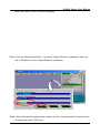
Step2: Run the TC++1.01development. Click the “Project\Open project…” create new
project named “TEST.PRJ”.
87
Publication August, 2013 Ver. 1.15
G-4500 Series User Manual
Step3: Use the “Add” function to add the library file into MyDemo project。
Step4: Following the step3, add another library and TEST.C into MyDemo project.
88
Publication August, 2013 Ver. 1.15
G-4500 Series User Manual
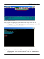
Step5: Click the “Options/Compiler/Code generation…” to set the compile mode to the
large mode. Click “More…” to set the “Floating point” and “Instruction Set”
parameters. The Emulation and 80186 will be used respectively. Then, click OK
button to save the configuration.
Step6: Click the “Option/Debugger...” to set the “Source Debugging” parameter.Here,
89
Publication August, 2013 Ver. 1.15
G-4500 Series User Manual
select the “None” for the “Source Debugging”.
Step7: Click the “Option/Directories...” to set the “Output Directory” parameter. Here, set
the “C:\MyDemo” for the “Output Directory” parameter.
Step8: After finishing all the parameters setting, click the “Compile/build all” toproduce the
execution file name “TEST.exe”.
90
Publication August, 2013 Ver. 1.15
G-4500 Series User Manual
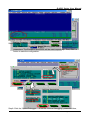
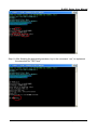
Step9: Copy the file 7188XW.exe into the MyDemo folder. Then, double-click the
7188XW.exe file.The 7188XW.exe can be found in the Osimage folder. And G-4500
series COM1 connected to the PC RS-232。
Step10: Key the command, “load” in the 7188xw.exe program. Then, follow the hint
command to press “Alt+E” and input the file name, “TEST.exe “, to download the
execution file.
91
Publication August, 2013 Ver. 1.15
G-4500 Series User Manual
Step11: After finishing the download procedure, key in the command, “run”, to implement
the execution file,”TEST.exe”.
92
Publication August, 2013 Ver. 1.15
G-4500 Series User Manual
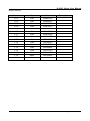
Version Record
Version
By
Date
1.0.1
Yide
2008/07/14
1.0.2
Yide
2008/09/12
1.0.3
Yide
2008/10/08
1.0.4
Yide
2008/10/15
1.05
Yide
2009/04/09
1.06
Yide
2009/05/13
1.07
Yide
2009/10/08
1.08
Yide
2009/11/30
1.09
Yide
2009/12/29
1.10
Yide
2010/06/10
1.11
Yide
2010/07/26
1.12
Yide
2010/08/24
1.13
Yide
2010/11/10
1.14
Yide
2011/11/09
1.15
Kane
2013/08/01
93
Description
Publication August, 2013 Ver. 1.15