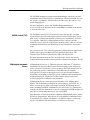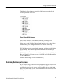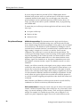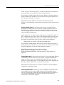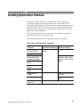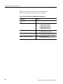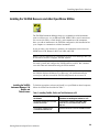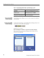
1
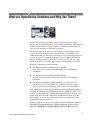
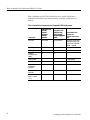
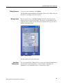
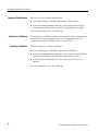
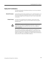
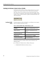
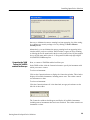
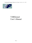
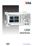
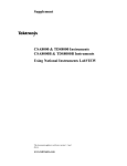
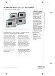
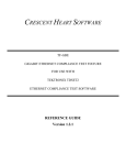
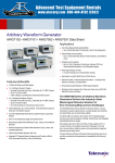
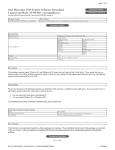
Basic Concepts
Getting Started with
OpenChoicet Solutions
071-1304-01
www.tektronix.com
Copyright © Tektronix. All rights reserved. Licensed software products are owned by Tektronix or its subsidiaries or
suppliers, and are protected by national copyright laws and international treaty provisions.
Tektronix products are covered by U.S. and foreign patents, issued and pending. Information in this publication supercedes
that in all previously published material. Specifications and price change privileges reserved.
TEKTRONIX and TEK are registered trademarks of Tektronix, Inc.
Mathcad is a registered trademark of MathSoft, Inc.
MATLAB is a registered trademark of The MathWorks, Inc.
ActiveX, Visual Basic, Visual C++, and Visual Studio are either registered trademarks or trademarks
of Microsoft Corporation in the United States and/or other countries.
LabVIEW and LabWindows/CVI are trademarks of National Instruments Corporation.
Tektronix, Tek, TekVISA, and OpenChoice are registered trademarks of Tektronix, Inc.
VEKTREX is a trademark of VEKTREX Electronic Systems, Inc.
NOTE: Software on the CD is provided AS IS with no warranties of any kind, specifically excluding WARRANTIES OF
MERCHANTABILITY AND FITNESS FOR A PARTICULAR PURPOSE. Tektronix, Inc. assumes no liability of any kind for
your use of this software.
Contacting Tektronix
Tektronix, Inc.
14200 SW Karl Braun Drive
P.O. Box 500
Beaverton, OR 97077
USA
For product information, sales, service, and technical support:
H In North America, call 1-800-833-9200.
H Worldwide, visit www.tektronix.com to find contacts in your area.
What are OpenChoice Solutions and Why Use Them?
OpenChoice Solutions are software resources that provide enhanced data
analysis and networking abilities for your Tektronix instruments. These resources
include software libraries, utilities, samples, and industry-standard protocols.
They are included with your Tektronix oscilloscope.
OpenChoice Solutions enable you to run, directly on your Tektronix oscilloscope, both off-the-shelf and custom-written software. They enable you to
communicate with your Tektronix oscilloscope over a network, using numerous
connectivity protocols and physical interfaces, such as GPIB, USB, Ethernet,
RS-232, and shared memory. OpenChoice resources provide you with a high
degree of flexibility to automate data acquisition, measurement, and analysis.
Examples of OpenChoice software include:
H
The Tektronix Toolbar for Microsoft Excel (TekXL),
which allows you to capture and graph oscilloscope data in MS Excel
spreadsheets
H
The Tektronix Toolbar for Microsoft Word (TekW),
which allows you to capture and graph oscilloscope data in MS Word
documents
H
The Tektronix OpenChoice Desktop(OCD) is an oscilloscope to PC
communication tool, which allows you to capture oscilloscope screen
images, waveform data, and settings from a Windows-based computer
Other OpenChoice resources support industry standard programming interfaces,
including the TekVISA API, VXIplug&play drivers, TekVISA Control (TVC)
ActiveX and Interchangeable Virtual Instruments (IVI) drivers, allowing you to
build custom solutions with commercially-available development tools and
environments. Later sections of this article provide more information about
programming interfaces and tools.
Different OpenChoice resources are available for current TDS1000, TDS2000,
TDS2000B, TDS3000B, DPO4000, TDS5000, TDS6000, TDS/CSA7000,
DPO7000, DPO/DSA70000 and TDS/DSA/CSA8000 series oscilloscopes.
Getting Started in OpenChoice Solutions
1
What are OpenChoice Solutiosn and Why Use Them?
Table 1 highlights specific TDS oscilloscope series, specific OpenChoice
components mentioned in this article that they work with, and the mode of
delivery.
Table 1: OpenChoice Components and Compatible TDS Oscilloscopes
2
Component
Compatible with
TDS1000,
TDS2000,
TDS2000B,
TDS3000,
DPO4000
Compatible with
TDS5000, 6000,
TDS/CSA7000/
DPO7000/DPO/DSA
70000
IVI Drivers
IVI-C drivers
IVI-COM drivers
IVC drivers can be downloaded from www.ni.com.
Keywords are ’tktds1k2k’,
’tktds3k’, ’tkdpo4k’
TekVISA
n
n
n
VXIplug&play
n
n
n
Software
Developer’s Kit
(SDK)
n
n
n
TekXL Toolbar
n
n
n with TekVISA
TekW Toolbar
n
n
n with TekVISA
National
Instruments
LabVIEW
n
n
n
MathWorks
MATLAB
n
n
n
Microsoft Visual
BasicR, Visual
C++R
n
n
n
Downloadable from
www.tek.com
(keyword: openchoice,
SDK)
Getting Started in OpenChoice Solutions
Choosing OpenChoice Tools
OpenChoice tools provide you with a multitude of choices and options. To help
you navigate through the alternatives and features, this article introduces some of
the key features and facilities provided.
OpenChoice tools support both off-the-shelf software applications, which you
can run as is, and custom software applications, which you design and code
yourself.
Using Off-the-Shelf Software Programs
Off-the-shelf software programs can solve your needs with only limited
programming or training required. As such, they often can provide a lower cost
solution than can software you write yourself. Tektronix provides several
off-the-shelf software programs based on the Microsoft Office suite. These
include the Tektronix Excel Toolbar, which copies your oscilloscope data into an
MS Excel spreadsheet, and the Tektronix Word Toolbar, which copies your data
into an MS Word document. Still another off-the-shelf software package is the
OpenChoice Desktop, which lets you capture oscilloscope screen images,
waveform data and instrument settings.
Availability of off-the-shelf software continues to expand as Tektronix and third
party developers add products to the OpenChoice collection.
Microsoft Office Solutions
Using the Tektronix Toolbar for Excel, a Microsoft Excel plug-in, you can
dynamically import data into a spreadsheet as your Tektronix oscilloscope
acquires it. The analysis capabilities of MS Excel can solve many oscilloscope
data analysis requirements. Excel sits on the line between being a true off-theshelf solution and being a programming environment. It provides many
opportunities to program. However, compared to most pure programming
languages, Excel is easier to learn to use — you may even be familiar with it
already. As the concept of the spreadsheet is relatively easy to grasp, you can
concentrate more on your problems and less on developing software.
Advantages of Excel include:
H
Widespread availability
H
Relatively low cost
H
Good basic graphing
Getting Started in OpenChoice Solutions
3
Choosing OpenChoice Tools
H
Widespread format compatibility
H
Relatively easy “what if” analyses where you can tweak the assumptions or
output
Table 2 on page 5 provides more details on this toolbar.
Using the Tektronix Toolbar for Word, a Microsoft Word plug-in, you can
dynamically import data into a Word document, as the data is produced by a
Tektronix oscilloscope. Table 3 on page 7 provides more details on this toolbar.
Other off-the-shelf oscilloscope software programs from Tektronix include:
Wavestar Software
Tektronix Application
Software Options
This Microsoft Windows 2000/NT/XP application brings Tektronix
oscilloscope measurement information to your PC desktop.
Application modules allow you to transform a Tektronix oscilloscope into a
specialized analysis tool able to perform advanced jitter and timing analysis,
10/100/1000BaseT validation, microprocessor memory system verification,
communications standards testing, disk drive measurements, video measurements, and power measurements.
While these programs are widely used for oscilloscope solutions, sometimes an
off-the-shelf program will not meet your needs. It may not meet engineering
needs for unique problem requirement situations or strategic needs to maintain
control of the software implementation. For many problems, a program you
write yourself may be the best choice.
The Tektronix Toolbar for
Excel (TekXL)
4
This toolbar, an add-in to Microsoft Excel, lets you capture and graph oscilloscope data in Microsoft Excel 2000, 2002, and 2003 spreadsheets.
Getting Started in OpenChoice Solutions
Choosing OpenChoice Tools
Table 2: The Tektronix Toolbar for Excel
The Tektronix Toolbar for Excel, as shown to the right, appears
inside your Microsoft Excel spreadsheet. To operate, click on the
appropriate toolbar button. Use the resulting dialog box to make
selections for the type of waveform and measurement data that
you want to capture and automatically paste into Excel.
Clicking the connection button displays all available
instruments, including remote instruments that have been
connected.
Clicking the settings button displays and transfers settings
between the oscilloscope and your computer.
Clicking the waveform button displays data and graphs the waveform, as shown below.
Getting Started in OpenChoice Solutions
5
Choosing OpenChoice Tools
Table 2: The Tektronix Toolbar for Excel (Cont.)
Clicking on the measurements button captures and displays single and repeated timed measurements.
Clicking on the triggered captures button captures and displays waveform data and waveform measurements on a trigger.
6
Getting Started in OpenChoice Solutions
Choosing OpenChoice Tools
The Tektronix Toolbar for
Word (TekW)
The Tektronix Toolbar for Word, an add-in to Microsoft Word, lets you capture
and graph oscilloscope data in Microsoft Word 2000, 2002, and 2003 documents.
Table 3: The Tektronix Toolbar for Word
The Tektronix Toolbar for Word, as shown to the right, appears
inside your Microsoft word document. To operate, click on the
appropriate toolbar button. Use the resulting dialog box to make
selections for the type of waveform and measurement data that
you want to capture and automatically paste into Word.
Clicking the connection button displays all available
instruments, including remote instruments that have been
connected.
The Tektronix OpenChoice
Desktop(OCD)
Clicking the settings button displays and transfers settings
between the oscilloscope and your computer.
The Tektronix OpenChoice Desktop lets you select the instrument and capture
oscilloscope screen images, waveform data, and settings from a windows-based
computer.
Screen Capture allows you to capture the current screen display from the
selected instrument and graph it on the application.
Waveform Data Capture allows you to acquire the selected waveform or
waveforms in numerical forms and as graphs.
Get and Send Settings allows you to capture and get display settings from the
selected instrument. It also allows you to send the current instrument settings to
the selected instrument or to multiple instruments.
Getting Started in OpenChoice Solutions
7
Choosing OpenChoice Tools
Figure 1: Tektronix OpenChoice Desktop
8
Getting Started in OpenChoice Solutions
Writing OpenChoice Software
Designing and implementing your own software program using the OpenChoice
tools allows you to tackle problems that off-the-shelf software does not address.
Tektronix oscilloscopes support a variety of industry-standard, OpenChoice
compatible programming environments and programmatic interfaces to help you
write your own software program.
Choosing a Development Environment
Examples of development environments in which to design and implement
custom software programs include National Instruments LabVIEW, The
MathWorks MATLAB, Microsoft Visual C++, Visual Basic, and VisualStudio.NET.
LabVIEW and Visual Basic are examples of visual software development
environments that permit relatively rapid development of the applications.
MATLAB and C/C++ are examples of software development environments that
provide powerful problem-solving features.
You should choose your development environments for each application with
care. Consider not only the intrinsic strengths of each environment, but also your
existing knowledge and access to each tool. The next section of this article
describes some of the alternatives and trade--offs that might influence your
choices of development environments from the large set of those available with
OpenChoice.
Table 4 lists some benefits of each of these development environment.
Table 4: Benefits of Different Development Environments
Development tool
Benefits
LabVIEW
H Graphical widgets and icons
H Comprehensive libraries for data collection, presentation,
and storage
H Relatively easy to learn
MATLAB
H Mathematical analysis and simulation capabilities
H Toolboxes for real-time control, signal processing, and
statistics
H C-style programming
H Multiple-platform, multiple OS support
Getting Started in OpenChoice Solutions
9
Writing OpenChoice Software
Table 4: Benefits of Different Development Environments (Cont.)
Development tool
Benefits
Visual Basic
H Custom user interfaces, read/write files, and plot results
that are easier to develop than in many other languages
H A quicker learning curve than many other languages
H A relatively low cost in materials and training to begin using
Visual C/C++
H Faster runtime execution speed than other languages
(especially C)
H Ability to implement complex algorithms
H Availability of numerous specialized code libraries
H Availability of numerous engineers who know how to
program C
H Object orientation in C++, which can permit faster
development, especially with complex application
interactions
H Support on multiple platforms and operating systems
(Windows, Macintosh, UNIX)
Choosing a Programming Interface
After you decide which programming environment to use, you need to decide
which programming interface to use. A programming interface is the software
layer between the code that programmers write in the programming environment
and the actual hardware. Tektronix provides several programming interfaces.
Tektronix programming interfaces include:
How to Choose an
Interface
H
TekVISA API: a ‘C’ library/DLL, which allows you to send and receive
ASCII commands using C function calls
H
VXIplug&play drivers: a ‘C’ library/DLL
H
IVI drivers: a COM-based interface, which uses the IVI standard
H
TekVISA ActiveX Control (TVC)
You may choose an interface because you find it much easier to use in specific
programming environments than others. For example, you may find it relatively
easy to use TekVISA ActiveX Controls (TVC) with Visual Basic.
You may choose some interfaces based on your level of comfort with the
oscilloscope-specific command set. For example, when you program the
instrument using the TekVISA API library, you will send the ASCII commands
10
Getting Started in OpenChoice Solutions
Writing OpenChoice Software
used in an oscilloscope-specific environment. Thus, it will help if you are
already familiar with this command set. Other interfaces do not require you to
understand the details of this command set.
All Tektronix open Windows oscilloscopes come with these programming
interfaces and associated documentation on the oscilloscope.
Also, you can directly program the oscilloscope using commands specific to
each model oscilloscope. All Tektronix open Windows oscilloscopes come with
documentation describing commands specific to that model. Frequently, this
documentation comes in MS-Windows online help and electronic PDF format.
Figure 2 on page 12 shows the relationship between these different programming
interfaces. Users can write programs in a variety of languages and use one of the
programming interfaces. All the other interfaces are built on top of the TekVISA
API, which provides the foundation for connectivity to the instrument. The
TekVISA API sends device-specific commands over USB, GPIB or LAN.
Getting Started in OpenChoice Solutions
11
Writing OpenChoice Software
Application Development Environments (ADE)
C, C++
Program
IVI-- COM
Visual Basic
Program
LabVIEW and
LabWindows
VXIplug &
play
TVC
MATLAB
TekVISA Input/Output Library API
Virtual GPIB
(GPIB8)
ASRL
GPIB
(GPIB0-- GPIB3)
(RS232 COM1,
COM2)
LAN
(VXI-- 11
Protocol)
USB
TekLink
Test and Measurement Instruments
Figure 2: The relationship between programming interfaces
Figure 3 on page 13 shows some of the tradeoffs between these interfaces. The
vertical represents portability of a program across different Tektronix oscilloscope models and the horizontal axis represents the abstraction or level of
commands provided by the interface.
12
Getting Started in OpenChoice Solutions
Writing OpenChoice Software
Figure 3: Trade-offs between programming interfaces
For example, the VXIplug&play driver is fairly low in the vertical axis
(portability) because there is a different interface for each oscilloscope model and
a client program would have to change if you used a different oscilloscope
model. The VXIplug&play driver is high on the horizontal axis (command level)
because it provides some higher-level functions like GetWaveform, which can
send multiple oscilloscope-model specific commands to the oscilloscope and
will return waveform data to the controller.
The TekVISA API is highly portable because a client program might not have to
change when developers use a different oscilloscope model. The TekVISA API is
fairly low on the X-axis, as it does not provide any higher-level functions. It just
allows you to use common ASCII (GPIB) programming commands on multiple
models of oscilloscopes that are compatible with the TekVISA API.
The IVI interface provides the best of both worlds: high-level functions and
results in a program that is portable across all TDS5000, TDS6000, TDS7000
and DPO7000 Tektronix OpenChoice real-time oscilloscopes.
TekVISA API: (Tektronix
Virtual Instrument
Software Architecture)
Test and measurement applications require some kind of I/O library to communicate with test instrumentation. As a step toward industry-wide software
compatibility, the VXIplug&play Systems Alliance (www.vxipnp.org) developed
a common I/O library called the Virtual Instrument Software Architecture (VISA).
VISA provides a common standard for software developers so that software from
multiple vendors, such as instrument drivers, can run on the same platform.
The TekVISA API is the Tektronix implementation of the Virtual Instrument
Software Architecture (VISA).
Getting Started in OpenChoice Solutions
13
Writing OpenChoice Software
The TekVISA API implements a subset of Version 3.0 of the VISA specification
for controlling GPIB and serial (RS-232) instrument interfaces locally or
remotely via an Ethernet LAN connection or USB. The TekVISA layer provides
the functionality needed to control and access the embedded software of
Tektronix test and measurement equipment in the following ways:
H
Using virtual GPIB software running locally on Windows-based instrumentation, such as TDS7000, DPO7000 and TDS8000 series oscilloscopes and
the CSA7000 and CSA8000 series communications analyzers. The TekVISA
API’s Virtual GPIB provides a software bridge to and from the embedded
oscilloscope software, permitting direct internal access to the oscilloscope
for much faster acquisitions than conventional GPIB ports.
H
Using physical GPIB controller hardware
H
Using asynchronous serial connections (for non-Windows-based oscilloscopes)
H
Using Local Area Network (LAN) with VXI-11 protocol. VXI-11 is an
industry standard protocol that can connect instruments over a LAN. A
VXI-11 server runs on the instrument, and the VXI-11 client is installed on
the remote PC controlling the instrument. The TekVISA API provides an
implementation of the VXI-11 server and client. If you want to connect
UNIX based systems to your Windows-based oscilloscopes, you will need
VXI-11 client software from another vendor (such as National Instruments)
or to create your own. Although Windows-based instruments have a direct
Ethernet connection, some non-Windows-based oscilloscopes may require a
GPIB to LAN adapter.
H
Using USB with instruments such as DPO4000 that supports the USB Test
and Measurement Class (USBTMC) specifications.
Figure 4 on page 15 shows some different connection scenarios, such as
programs running on the oscilloscope controlling the instrument and remote PCs
running Windows or UNIX.
14
Getting Started in OpenChoice Solutions
Writing OpenChoice Software
Remote
Windows- based Controller
Remote
UNIX- based Controller
Local
Windows- based Controller
User
Application
User
Application
VXI-- 11
Client
Ethernet
LAN
Windows- based
Oscilloscope
Windows-- side
of Instrument
TekLink
VXI-- 11
Client
ASRL
VISA Library
VISA Library
VXI-- 11
Client
User
Application
User
Application
ASRL
GPIB
GPIB-- LAN Adapter
w/VXI-- 11 / Ethernet LAN
Ethernet
LAN
Embedded Software side
of Instrument
USB
USB
Hardware
GPIB
Hardware
RS-- 232
Hardware
VXI-- 11
Server
VISA Library
GPIB
software
GPIB
connection
Virtual
GPIB
Non Windows- based
Instruments
Figure 4: Different connection scenarios
The TekVISA API software comes standard in Tektronix open Windows-based
oscilloscopes.
You can use a variety of programming environments including MATLAB, Visual
Basic, LabVIEW and Visual C++ to program the instrument using the TekVISA
API. Other sections of the OpenChoice SDK documentation provide more
examples using these environments.
The TekVISA Programmer Manual includes a lookup reference section and a
tutorial section with programming examples. You can find a copy either in the
OpenChoice Software Developers’ Kit, with your MS Windows TDS Oscilloscope product disk, or online at www.tektronix.com.
Getting Started in OpenChoice Solutions
15
Writing OpenChoice Software
The actual commands sent by the TekVISA API are the same as those documented in the programmer manual for each oscilloscope. This means that a client
software program written using VISA is portable across different oscilloscope
models if the underlying oscilloscope-specific command set is the same. For
example, since the TDS5000, TDS6000, DPO7000 and TDS7000 series use
similar commands and the TDS8000 uses different commands, it is much easier
to extend a TDS5000 program to work with the TDS6000 and TDS7000 series
models than with the TDS8000 series models.
Two different implementations of VISA exist in the industry: VISA-C and
VISA-COM. Tektronix offers a C-based VISA but not a COM-based VISA.
VISA defines an architecture consisting of many resources that make up the
instrument functionality. Applications that use VISA access device resources by
opening sessions to them. A session is a communication path between a software
element and a resource. Every session in VISA is unique and has its own life
cycle. VISA defines a locking mechanism to restrict access to resources for
special circumstances. After establishing a session, an application can communicate with a resource by invoking operations associated with the resource or by
updating characteristics of resources called attributes. A VISA system also
allows information exchange through events.
VISA Resource Manager is the name given to the part of VISA that manages
resources, including support for opening, closing, and finding resources; setting
and retrieving resource attributes; generating events on resources; and so on. The
VISA Resource Manager provides access to all resources registered with it. The
Default Resource Manager, which is available after initialization, is used when
you open resources, find available resources, or perform other operations on
device resources.
Unique address strings called VISA descriptors identify VISA resources. These
descriptors are also used by IVI and VXIplug&play drivers.
Here are some examples of these strings:
GPIB0::8::INSTR refers to the GPIB device on board 0 at primary address 8.
TCPIP::555.555.555.55::INSTR refers to a networked instrument with IP
address 555.555.555.55
GPIB8::1::INSTR is used to identify the virtual GPIB connection, which is
used when engineers run the program on the Tektronix open Windows
oscilloscope.
USB0::16894::1025::Q10033::0::INSTR is used to identify the USB
connection which refers to a USBTMC device with manufacturer ID 16894,
model code 1025, and serial number Q10033 and 0 is the interface number
of the device.
16
Getting Started in OpenChoice Solutions
Writing OpenChoice Software
The TekVISA installation includes a Instrument Manager, which lets you find
instruments, and a Talker/Listener to communicate with the instrument. You can
also access a Call Monitor, which monitors all VISA calls. This can be a very
useful debugging tool.
For more information, refer to the TekVISA Programmer Manual
(071-1101-XX) on the Reference section of the SDK or available for download
at www.tektronix.com.
TekVISA Control (TVC)
The TekVISA Control (TVC) is an ActiveX control that provides a wrapper
around VISA. It provides some high-level functions like GetWaveform, which
make it easy to transfer data from the oscilloscope in a Visual Basic or Visual
C++ program. Unlike IVI or VXIplug&play drivers, it does not provide
functions to access all of the oscilloscope’s capability, and it relies on low level
commands like ReadString and WriteString to send commands to the oscilloscope.
You can also use the TVC to develop programs in Visual Basic for Applications
(VBA), which comes with Microsoft Excel and Word applications. The
Tektronix Excel Toolbar was developed in VBA and uses the TVC.
For more information about the TVC ActiveX control, refer to the ActiveX
Control Online Help available on the OpenChoice Software Developers’ Kit CD.
VXIplug&play Instrument
Drivers
VXIplug&play drivers are ‘C’ DLLs that provide a functional ‘C’ interface to
instruments. Because these DLLs expose the functionality of the oscilloscope
with a collection of C functions, you do not have to deal with the intricacies of
the oscilloscope-specific command sets. Some functions (for exampleSetTriggerLevel, which sets the trigger level of a scope) are small wrappers
around the corresponding oscilloscope-specific command. Other functions like
GetWaveform provide a higher level of functionality and can send several
oscilloscope-specific commands to the instrument.
VXIplug&play drivers conform to the specifications of the VXIplug&play
alliance. Get the detailed specifications at www.vxipnp.org. Since these are ‘C’
DLLs, use these drivers from a wide range of software development environments, including LabVIEW, LabWindows/CVI, and Visual C++. Tektronix has
worked with National Instruments to provide customized LabVIEW wrappers for
these drivers, which make them easy to use in LabVIEW.
Each Tektronix oscilloscope model has a different VXIplug&play driver. Unlike
IVI drivers discussed later, these drivers do not standardize on different classes
of instruments. For example, the interface to a different vendor’s oscilloscope
may be very different from the interface to a Tektronix oscilloscope.
Getting Started in OpenChoice Solutions
17
Writing OpenChoice Software
IVI Drivers:
(Interchangeable Virtual
Instruments)
IVI drivers are a new generation of drivers. They conform to specifications
produced by the IVI Foundation (www.ivifoundation.org). Unlike VXIplug&play drivers, they provide a standard interface to different classes of
instruments, including oscilloscopes and spectrum analyzers.
There are two parts to an IVI driver, a class-compliant part which conforms to
the class specification provided by the IVI Foundation and a specific part which
provides access to extended capabilities provided by a specific instrument. These
provide the developers with the ability to take advantage of specific unique
capabilities of each vendor’s instrument. An example is a special triggering
mode of an oscilloscope.
IVI drivers can provide increased features and better quality than earlier drivers.
They include the ability to simulate instruments, automatically check ranges, and
multithread safety features. Multithread features allow the program to call a
driver more than once, potentially increasing the speed of the program. Simulation features let the program work without having access to the actual hardware.
This helps you create and debug your software even if the hardware is not
available. You can also achieve better interchangeability of instruments from
different vendors by programming only to the class specification.
IVI drivers can be implemented using C or COM technologies. IVI-C drivers
expose a ‘C’ language. IVI-COM drivers have an API based on Microsoft COM
technology. Tektronix has worked with National Instruments to provide IVI-C
drivers for the TDS1000, TDS2000, TDS3000 and DPO4000 series oscilloscopes.
Tektronix provides a single IVI-COM driver for TDS5000, TDS6000, DPO7000
and TDS7000 series oscilloscopes. This driver implements the class-compliant
part, which conforms to the IVIScope specification provided by the foundation.
It also provides a specific part, which provides access to all the extended
capabilities provided by the instrument.
18
Getting Started in OpenChoice Solutions
Writing OpenChoice Software
The following figure illustrates some of the COM interfaces provided by the
oscilloscope portion of the driver:
Figure 5: Some IVI COM interfaces
Some of these interfaces, such as WaveformTransfer, provide high-level
functions that make it very easy to acquire a waveform, save that waveform to a
file, or copy it to the Windows clipboard. Other interfaces, such as Acquisition
and Horizontal, provide fine-grained control over different oscilloscope
attributes.
IVI-COM drivers require several shared components, which are provided by the
IVI Foundation. These shared components are installed in all Tektronix open
Windows oscilloscopes.
IVI-COM drivers integrate seamlessly with Microsoft environments like Visual
Basic and Visual C++. You can also use the LabVIEW and MATLAB capability
to call COM interfaces.
For more information, go to: www.ivifoundation.org.
Designing Oscilloscope Programs
If you decide to design your own oscilloscope application program, this section
is for you. You know what you want your program to do. Now, how do you
actually write an oscilloscope software application? What tips and tricks might
help you to make it work, run fast, and transfer data from the oscilloscope to the
PC as quickly as possible?
Getting Started in OpenChoice Solutions
19
Writing OpenChoice Software
If you are using the functions provided in IVI or VXIplug&play drivers
described in the previous section, you will not have to use the device-specific
commands described in this chapter. You can still apply some of the same
general principles and use equivalent functions provided in these drivers. Of
course, you still use these device-specific commands when you program using
the TekVISA API.
To ensure that your oscilloscope software application will run correctly, follow
these steps:
Set up the oscilloscope
H
Set up the oscilloscope.
H
Retrieve the data.
H
Analyze the data
Initialize the scope settings. The instrument needs to begin activities from a
known state. The factory-initialized settings serve well for this task. Find the
factory default settings listed in the programmer on-line guide or the user manual
for an oscilloscope. The defaults set up the instrument by defining the vertical
(volts/division), horizontal (time base, seconds/division), acquisition mode, and
trigger settings. A simple way to do this is to send the ‘autoset execute’
command to the oscilloscope or to press the Autoset front-panel button. The
oscilloscope will attempt to figure out the best settings for the signals sensed by
the probe. Depending on the oscilloscope model, the channel used for autoset
might be the lowest channel number that is on or the channel with the lowest
frequency signal. If no channels are on, the autoset command may turn on the
first channel it encounters that has a signal. The default for autoset is to select
channel #1.
Usually, you will have some idea of the signal you are going to analyze with the
oscilloscope, and you know which parts of the signal are of most interest to you.
Autoset may not provide the appropriate representation of the signal of interest.
In those cases, (and when autoset simply fails to display a signal) users will need
to set the parameters differently than autoset did during its experiments. In other
words, autoset may get the signal on the screen but users should be prepared to
set vertical, horizontal, triggering and acquisition values that fit their current real
world need.
Many Tektronix open Windows oscilloscopes use the device-specific FACTory
command to set activities to the factory-initialized, known state.
Set the vertical values. In setting the vertical scale (per div value) of the specified
channel, consider the dynamic range of the oscilloscope. As you use more of this
range, you can take advantage of more accuracy. Thus, use logical volts/division
settings. For example, let’s consider the case where you are using the 5-volt
square wave probe compensation signal. There are 8 vertical divisions on the
20
Getting Started in OpenChoice Solutions
Writing OpenChoice Software
screen. If you set the vertical scale to 1 volt/division, then the wave will nicely
use most of the screen. It will fill 5 of the 8 vertical divisions.
You could use a smaller volts-per-division scale. However, then fewer pixels of
display information would show for each waveform. The typical approach is to
show as much resolution as is practical.
Many Tektronix open Windows oscilloscopes use the device-specific
CH<x>:SCAle command to set the vertical scale (per div value) of the specified
channel.
Set the horizontal values. For horizontal values, set the record length. This
determines how many points you can store in a single acquisition. There is a
limit. Once the oscilloscope reaches the limit, then it cannot store new points
without dropping off old ones. Also, the oscilloscope acquires the data on all
selected channels synchronously.
Again consider the case where you are using the probe compensation signal. It
has a 1-kHz square wave signal. There are 10 horizontal divisions on the screen.
If two complete waveform cycles show, that would be 2 milliseconds of data.
Since there are 10 divisions across the screen, each division should have
2 milliseconds / 10 divisions = 200 microseconds/division.
You could use a smaller time per division scale; however, then fewer pixels of
display information would show for each waveform. As with the vertical values,
the typical approach is to show as much resolution as practical.
Many Tektronix oscilloscopes use the device-specific
HORizontal:RECOrdlength to change the record length or
HORizontal:MAIn:SAMPLERate to change the rate at which samples are
digitized.
Set the trigger values. Set the trigger type and level. Use the appropriate TRIGger
command to get the job done the way you want it. Using this command, the
trigger can be set to occur on: a rising or falling edge, on a level, on a logic
pattern, on a pulse width, and so on. You should also select video triggering and
then choose between fields, lines, or a specific line number.
Many Tektronix oscilloscopes use a variation on the device-specific TRIGger
command to set the trigger values.
Set the acquisition mode. Oscilloscopes come with different acquisition modes,
such as sample, peak-to-peak, and high resolution. In choosing the mode to
select in your programs, consider the trade-off between effective resolution of
your waveform data and the time it takes to transfer that data from your
oscilloscope to your remote computer.
Getting Started in OpenChoice Solutions
21
Writing OpenChoice Software
For example, your oscilloscope’s sample mode may store each point of data in a
single byte and thus your program may relatively quickly transfer data, but with
the limitation that your program receives relatively few levels of resolution to
analyze. In contrast, the high-resolution mode may store each point of data with
multiple bytes. Thus your program may transfer data relatively slower, but with
more levels of resolution to analyze.
For example, a program controlling many Tektronix oscilloscopes might use
high-resolution sampling that acquires data with more detail (14 bits) but fewer
data points in the same time period compared to a program controlling an
oscilloscope using a sample mode with less detail (8 bits). Not all oscilloscopes
use the same number of bits per point. The TDS/CSA8000, for example, uses
14-bits in its sample mode.
Understand the difference between equivalent time and real time acquisition.
Equivalent time waveforms are the sum of many triggers. Real time is the result
of a single trigger.
Many Tektronix oscilloscopes use the ACQuire commands to get the acquisition
required for an application.
Retrieve the data
You can get two things out of your oscilloscopes. You can get measurement data
and waveform data. What the oscilloscope sees is the same whether the program
was written in C, Visual Basic, or another language.
Considerations for retrieving measurements. There are two measurement types,
immediate and not-immediate. Use non-immediate to display measurements on
the oscilloscope front-panel screen. Use immediate if you do not want the
measurements displayed on the screen.
You can drive the waveform update rate faster if you use immediate measurements rather than displayed measurements because immediate measurements are
computed only when needed.
Many Tektronix oscilloscopes use the device-specific MEAS:MEAS and
MEAS:IMMEDiate commands for retrieving measurements. MEAS:MEAS
displays measurements on the oscilloscope front-panel screen. MEAS:IMMEDiate does not display the measurements on the screen.
Considerations for retrieving data. There are two waveform query types. (If you
use IVI and VXIplug&play drivers, you do not have to deal with the device
specific commands described below because these drivers provide higher-level
functions for getting the data.)
The first type of query returns a preamble followed by a binary block. The
preamble contains data that users need to properly scale the data back into volts
and seconds.
22
Getting Started in OpenChoice Solutions
Writing OpenChoice Software
The second query type also returns a binary block. This type query returns only
the binary block. It does not return a preamble. This makes it a little faster than
the first type with the preamble and is typically used after the preamble values
have been obtained one time. The preamble values will remain the same until the
programs change the settings of the oscilloscopes. For many oscilloscope
models, the data comes in a 2-byte format. The data will be in 1-byte or 2-byte
per sample point format depending on the setting of the DATA:WIDTH parameter. When averaging or hi-resolution acquisition modes have been selected, the
increased resolution is conveyed in the 2-byte data. In other acquisition modes
there will be no significance in the use of 2-byte data.
The binary block structure consists of #xyyynnnn.....LF, where the x value
represents the number of y bytes. The y bytes represent the record length. The n
values are the digitizing levels for each sample and a linefeed character
terminates the block.
With a 5,000-point record length, this means a 10,000-byte chunk of data. For
example, if a user had a 10,000 point record length, then the block would be
#510000nnnnnnn.....LF.
Not all oscilloscopes work exactly this way. The TDS8000 and CSA8000, for
example, supports a four-byte, 32-bit data format.
Many Tektronix OpenChoice oscilloscopes use the device-specific WAVFM?
query to return the preamble followed by the binary block. They use the
CURVE? query to return the binary block without a preamble.
Decide on the data path to use in retrieving data. How do you want the data to
flow from your oscilloscope to your custom application? With Tektronix open
Windows oscilloscopes, such as the TDS5000, TDS6000, TDS7000, and
TDS8000, you can run your applications on the computers built into your
oscilloscopes to take advantage of the fast internal PCI bus. Alternatively, you
can run your application on a separate computer connected to your oscilloscope
by GPIB, RS-232, or Ethernet to take advantage of special processing or storage
abilities of the remote machine.
Decide on the type of synchronization to use in retrieving data. Use synchronization to ensure that the acquisition process is completed before your program
proceeds to the next task. Synchronization helps assure your program acquires
the data you want it to acquire. Three common forms of synchronization
methods are the *OPC, SRQ, and BUSY methods. *OPC and BUSY use polling
that require the program to loop through repeated queries of the oscilloscope
state. The SRQ method directs the scope to interrupt the application program
rather than rely on repetitive polling. While the SRQ method is more difficult to
program, it typically provides the most effective approach for programming
multiple instrument systems.
Getting Started in OpenChoice Solutions
23
Writing OpenChoice Software
*OPC: great for single oscilloscope applications.
SRQ: great for multiple instrument networks. OPC tends to take up too
much time in a multiple instrument setup.
BUSY: easy to program, but inefficient.
Refer to the specific oscilloscope programming guide for more details on each
synchronization method.
Error Handling. When done retrieving the data, check for errors so that you can
tell if the acquisition worked.
Typical error handling involves testing the status registers. To do this, have the
programs send the oscilloscope an *esr? query. If the programs return a nonzero
value, this indicates that an event of some sort occurred. Now, decide how your
program should handle the event. A simple to implement way is to display a
message that says an error occurred. Perhaps, it can also refer the user to an
appropriate specific oscilloscope programmer manual for more information on
the error code. A more involved, but more helpful, message would tell the user
exactly what message occurred. To do this, you can mask the error code through
register templates to decode the specific event that occurred. You could then
display the name of this specific event in a message to the user.
Data Encoding. One way to speed up the transfer of data from oscilloscopes to
PCs is to choose the best format for the data. In choosing a format, you should
consider that although oscilloscopes can format the data, your program typically
runs faster when you convert the data in the PC rather than in the oscilloscope. In
other words, you should use binary formats for speedier operation.
You can format the data in several ways, such as in ASCII, RP binary, or RI
binary format. You can obtain better transfer times by using a binary format,
such as the RI one, which is the default on many oscilloscope models. However,
to use the data in many applications, you must process this data back to an
ASCII format after it arrives in the PC.
Speaking of binary formats, for many oscilloscope models, the difference
between RP Binary and RI Binary is that RP Binary goes from 0 to 255 and RI
Binary goes from --127 to +128.
For more information on supported data formats, refer to the data:encdg
command in your instrument programmer guides.
Remember to match the decoding portion of your programs to the coding
portion. In other words, if you change data encoding formats, then remember to
change the decoding portion of the program as well.
24
Getting Started in OpenChoice Solutions
Writing OpenChoice Software
Analyze the data
Once you have collected a waveform in binary format and transferred it to your
PC, you should convert the waveform data into volts. If you are using VXIplug&play or IVI drivers, these calculations are done for you automatically.
To convert the waveform data into volts, use the waveform preamble from the
appropriate waveform query (WAVFRM? for many Tektronix oscilloscopes).
In many Tektronix oscilloscopes, sample mode data contains 256 digitizing
levels. Programs typically convert this to volts with the YOFF, YPOS, and
YMULT values. YOFF defines the position of the waveform trace on the display.
YPOS represents the DC offset.
For example, to convert RPBinary data format to voltage, the algorithm is:
Voltage = (Digitizing Level -- YOFF) * YMULT
In these Tektronix oscilloscopes, each digitizing level represents one part in 256
if the data width is set to 1. The screen shows only 8 divisions of a total of
10.24 divisions. This results in 25 digitizing levels per division. Referring back
to our example of measuring the 5-volt probe compensation signal with the
represented by a value of 125. The YMULT should be 4.0e-2 or 40mV per
digitizing level. If you do not use an offset and you do apply the scaling
algorithm, the results will be:
5 volts = (125 -- 0) * 0.04
Final Tips for Getting Accurate Measurements. To ensure the oscilloscope provides
as accurate as possible a representation of the signal for your analysis, refer to
the following procedure. If you encounter difficulties, you should refer to the
oscilloscope online help or user manual.
1. Allow the oscilloscope to warm up to proper operating temperature (usually
no more than 20 minutes).
2. Perform a signal path compensation (SPC) to minimize DC inaccuracies
caused by temperature variations or long-term drift. Most Tektronix
oscilloscopes provide an automated SPC routine that you start by clicking a
pull down menu or by pushing a couple of buttons. Disconnect all probes
from all channels when performing SPC.
3. Connect the probe(s) to the channels they are going to use and check that the
probe attenuation is what you want for your application. Some probes use a
switch to change attenuation. Make sure your probes can handle the
frequency of the signal you are interested in measuring. Also, check to be
sure the attenuation on the oscilloscope for a particular channel is set to the
same attenuation as that of the probe connected to that channel. Some
Tektronix oscilloscopes have an automated method of verifying that the
attenuation of the probe and the oscilloscope channel attenuation settings are
Getting Started in OpenChoice Solutions
25
Writing OpenChoice Software
the same. If they are not the same, the measurements results will not be
meaningful.
4. Check the compensation of each probe. (If you move a probe to another
channel, check the compensation for the new channel.) To check probes for
testing purposes, you can connect them to the probe compensation signals on
the front panels of most oscilloscopes. Again, some Tektronix oscilloscopes
have a probe check feature that guides you through probe compensation
activities and verifies that the probe is performing acceptably.
5. Remember to then connect the probe(s) to the device-under-test (DUT).
26
Getting Started in OpenChoice Solutions
Installing OpenChoice Solutions
Installing OpenChoice solutions is straightforward. Your open Windows
oscilloscope typically comes from the factory with the various drivers and
off-the-shelf solutions preinstalled. If needed, you can install OpenChoice drivers
and off-the-shelf solutions on your Windows-based computer by downloading
files from the www.tektronix.com or running install scripts from the attached
OpenChoice Solutions SDK CD.
You can install development environments for custom software development
using CDs provided by the appropriate vendor.
Table 5 lists various OpenChoice components and where to find them.
Table 5: Where to find OpenChoice components
Component
Install and uninstall on an
open Windows oscilloscope
Install and uninstall on an
MS Windows computer
Interchangeable Virtual
Instrument (IVI) drivers
Installed from factory on TDS
disk drive
Download from Web or SDK
CD
VXIplug&play drivers
OpenChoice Instrument
Manager, Talker/Listener,
Call Monitor and TekVISA
Download from Web. Single
download for TekVISA, TekVISA Controls, TekXL, and TekW
T lb
Toolbars
TekVISA Controls (TVC)
ActiveX
Tektronix Toolbar for Excel
(TekXL)
Tektronix Toolbar for Word
(TekW)
National Instruments
LabVIEW
Purchase a copy from National
Instruments
MathWorks MATLAB
Purchase a copy from MathWorks
Microsoft Visual Basic and
Visual C/C++
Getting Started in OpenChoice Solutions
Purchase a copy from Microsoft
27
Installing OpenChoice Solutions
Table 6 shows the default locations where various OpenChoice
Solutions components are installed on the host hard disk.
Table 6: Hard disk locations for OpenChoice components
Component
Location
Interchangeable Virtual Instrument (IVI) C:\program files\IVI
drivers
28
VXIplug&play drivers
For MS WinNT PCs (includes XP),
C:\VXIPNP\WinNT\TKTDS5k
C:\VXIPNP\WinNT\TKTDS6k
C:\VXIPNP\WinNT\TKTDS7k
C:\VXIPNP\WinNT\TKTDS8k
TekVISA Controls (TVC) ActiveX
For MS WinNT PCs (includes XP),
C:\VXIPNP\WinNT\TekVISA\Bin
Tektronix Toolbar for Excel (TekXL)
For MS WinNT PCs (includes XP),
C:\VXIPNP\WinNT\TekVISA\ExcelToolbar
Tektronix Toolbar for Word (TekW)
For MS WinNT PCs (includes XP),
C:\VXIPNP\WinNT\TekVISA\WordToolbar
Getting Started in OpenChoice Solutions
Installing OpenChoice Solutions
Installing the TekVISA Resource and other OpenChoice Utilities
The TekVISA Instrument Manager helps you communicate with instruments,
such as oscilloscopes, over an Ethernet LAN, GPIB, USB or serial connections.
You can use this utility to find, identify, and communicate with instruments.
Once you add an instrument to the TekVISA configuration, this installation lets
your computer to communicate with the instrument.
It also provides a user interface to optimize your instrument search criteria for
GPIB, Serial, VXI, Remote LAN, Local LAN, and USB.
NOTE. If you are connecting to a network just to print screen hardcopy data, you
do not need to install or configure TekVISA software.
You need to install and configure the TekVISA API on each PC that communicates with Tektronix instruments using the VISA standard.
NOTE. If you have already installed the TekVISA API from an earlier version of
the Tektronix Software Solutions CD or Wavestar, you should uninstall that
version first, and then reinstall the TekVISA API from the most recent CD.
Installing the TekVISA
Instrument Manager, Call
Monitor and
Talker/Listener
To find the appropriate software and install it on your Windows-based computer,
follow the instructions described in Table 7.
Table 7: Installing TekVISA, TekXL, and TekW Software on a PC
Alternative Locations for Finding
the Software
Instructions for Installing the Software on a PC
The product software CD for a current
Windows oscilloscope
In your Windows computer, select Start > Run,
browse the CD to the TekVISA folder, and run
setup.exe.
The TDSPCS1 OpenChoice PC
Communications Software CD
Follow the instructions in the CD’s installation wizard.
Getting Started in OpenChoice Solutions
29
Installing OpenChoice Solutions
Table 7: (Cont.)Installing TekVISA, TekXL, and TekW Software on a PC
Alternative Locations for Finding
the Software
Instructions for Installing the Software on a PC
The OpenChoice Solutions Software
Developers’ Kit CD
Click on the Developers’ Kit CD’s browser button for
Software Drivers and then for TekVISA
The current TekVISA installation
download from the Tektronix Web site
Unzip the downloaded file in a temporary directory of
your choice and run setup.exe.
Running the TekVISA
Instrument Manager
The TekVISA Instrument Manager lets you to search, manage and communicate
with instruments.
Launching the TekVISA
Instrument Manager
To launch Instrument Manager, click TekVISA Resource Manager utility icon in
the system tray as shown in the following figure.
Alternatively, you can select,
Start > All Programs > TekVISA > OpenChoice Instrument Manager.
Either method will open the Instrument Manager window similar to the one
shown in the following figure.
Figure 6: Instrument Manager
30
Getting Started in OpenChoice Solutions
Installing OpenChoice Solutions
Finding Resources
To search for new instruments, click Update.
The TekVISA Instrument Manager automatically detects Serial, GPIB, USB, and
LAN devices operating on the local network.
Making a Search
For new search criteria, click Select Criteria. The Search Criteria dialog box
displays as shown in the following figure. The options vary depending on your
computer and the available network. Select the communication type you want to
include in the search criteria.
Figure 7: Search Criteria
For more details, refer to the online help.
OpenChoice
Talker/Listener
You can use OpenChoice Talker/Listener to observe the detailed communication
between the PC and the instruments, to send individual commands to the
instruments, to run commands scripts, to create and save scripts.
Getting Started in OpenChoice Solutions
31
Installing OpenChoice Solutions
Launching Talker/Listener
There are two ways to launch Talker/Listener:
H
Start >All Programs > TekVISA > OpenChoice Talker Listener.
H
From the Instrument Manager dialog box, select Applications and Utilities>OpenChoice Talker Listener, and click “Start application or Utility”.
For more information, refer to the online help.
OpenChoice Call Monitor
Launching Call Monitor
The OpenChoice Call Monitor captures and displays all VISA communications
between the PC and any instrument that it is in communication with. The
communication includes TekVISA ActiveX Control (TVC).
There are three ways to launch Call Monitor:
H
Start > All Programs > TekVISA > OpenChoice Call Monitor.
H
From the Instrument Manager dialog box, select Applications and Utilities>
OpenChoice Call Monitor, and click “Start Application or Utility”.
H
Click Visa Resource Manager icon in the system tray and select Call
Monitor.
For more information, refer to the online help.
32
Getting Started in OpenChoice Solutions
Installing OpenChoice Solutions
Deployment Considerations
To realize the full benefits of LAN-based oscilloscope access, keep in mind the
following considerations:
Network Performance
Network Security
Actual oscilloscope data transfer performance across a LAN will depend on your
network’s physical type and composition of hubs, switches, and routers. It may
be necessary to upgrade network components in order to achieve optimal LAN
access speeds.
As with any other computing resource attached to a network, take security
precautions as appropriate to protect your LAN-enabled oscilloscope against
unauthorized use.
CAUTION. If your organization’s LAN is connected to external networks such as
the Internet, use of a properly configured network firewall is strongly recommended. The VXI-11 protocol and VXI-11 LAN Server do not include any
security mechanisms.
The vast majority of businesses and other organizations with Internet access
already have network firewalls established. However, you may want to contact
network security personnel to verify that your firewall blocks external access to
the RPC port mapper service (TCP/IP port 111). VXI-11 clients use this network
software service to connect to the VXI-11 LAN Server.
Getting Started in OpenChoice Solutions
33
Installing OpenChoice Solutions
Installing the Tektronix Toolbar for Excel (TekXL)
The Tektronix Toolbar for Excel, an add-in to Microsoft Excel, lets you capture
and graph oscilloscope data in Microsoft Excel 2000 and 2002 spreadsheets.
The toolbar consists of a list of buttons as shown in the following figure. These
let you connect to an instrument, transfer settings between the instrument and the
computer, capture waveform screenshots, capture waveform numerical data, and
capture measurements.
Installing the TekXL
Toolbar
To find the appropriate software and install it on your Windows-based computer,
follow the instructions described in Table 8.
Table 8: Installing TekVISA, TekXL, and TekW Software on a PC
Alternative Locations for Finding
the Software
Instructions for Installing the Software on a PC
The product software CD for a current
Windows oscilloscope
In your Windows computer, select Start > Run,
browse the CD to the TekVISA folder, and run
setup.exe.
The TDSPCS1 OpenChoice PC
Communications Software CD
Follow the instructions in the CD’s installation wizard.
The OpenChoice Solutions Software
Developers’ Kit CD
Click on the Developers’ Kit CD’s browser button for
Software Drivers and then for TekVISA
The current TekVISA installation
download from the Tektronix Web site
Unzip the downloaded file in a temporary directory of
your choice and run setup.exe.
The Tektronix OpenChoice installer normally loads the TekXL files in the
following location:
H
For Windows NT, Windows 2000, or Windows XP systems:
C:\VXIPnP\WinNT\TekVISA\ExcelToolbar directory
34
Getting Started in OpenChoice Solutions
Installing OpenChoice Solutions
The installation will also place a Toolbar Start Preferences button on your
desktop, as shown in the following figure.
If you click on the button, the Tektronix Toolbar Startup Preferences window
will appear, as shown in the following figure.
You can use this window to control the operation of the toolbars.
Click on Launch when Excel is started to have the TekXL Toolbar appear
whenever you start MS Excel.
Click on Just add to Add-Ins List if you do not wish the TekXL Toolbar to
appear whenever you start MS Excel. This will leave the Tekxltoolbar entry
deselected on the Excel > Tools > Add-Ins list.
Connecting the TekXL
Toolbar to a TekVISA
enabled Oscilloscope
Next, to connect to TekVISA enabled oscilloscopes:
In theTekXL toolbar, click the Connection button to specify the instrument with
which you want to connect.
To select an instrument:
Click the Connection button. It is the functional, non-grayed out button on the
left of the toolbar.
Getting Started in OpenChoice Solutions
35
Installing OpenChoice Solutions
The Connection window should appear and display all available instruments,
including remote instruments that have been connected. The toolbar controls one
instrument at a time.
The following figure shows the Connection window.
Figure 8: TekXL Connection
To see the model number for an instrument, click its entry once, and then click
the Identify button to the right. The model number will appear at the bottom
pane of the Connection box, as shown in the following figure.
Either double-click the entry for the instrument that you wish to connect to or
click the entry once and then click the OK button. A successful connection is
indicated by the grayed-out, non-functional toolbar buttons becoming functional,
as shown in the following figure.
36
Getting Started in OpenChoice Solutions
Installing OpenChoice Solutions
You can find further information on operating the toolbar in the online help.
Installing the Tektronix Toolbar for Word (TekW)
The Tektronix Toolbar for Word, an add-in to Microsoft Word, lets you capture
and graph oscilloscope data in Microsoft Word documents.
The toolbar consists of a list of buttons as shown in the following figure. These
let you connect to an instrument, transfer settings between the instrument and the
computer, capture waveform screenshots, capture waveform numerical data, and
capture measurements.
Installing the TekW
Toolbar
To find the appropriate software and install it on your Windows-based computer,
follow the instructions described in Table 9.
Table 9: Installing TekVISA, TekXL, and TekW Software on a PC
Alternative Locations for Finding
the Software
Instructions for Installing the Software on a PC
The product software CD for a current
Windows oscilloscope
In your Windows computer, select Start > Run,
browse the CD to the TekVISA folder, and run
setup.exe.
The TDSPCS1 OpenChoice PC
Communications Software CD
Follow the instructions in the CD’s installation wizard.
The OpenChoice Solutions Software
Developers’ Kit CD
Click on the Developers’ Kit CD’s browser button for
Software Drivers and then for TekVISA
The current TekVISA installation
download from the Tektronix Web site
Unzip the downloaded file in a temporary directory of
your choice and run setup.exe.
The Tektronix OpenChoice installer normally loads the TekW files in:
H
For Windows NT, Windows 2000, or Windows XP systems
C:\VXIPnP\WinNT\TekVISA\WordToolbar directory
Getting Started in OpenChoice Solutions
37
Installing OpenChoice Solutions
The installation will also place a Toolbar Start Preferences button on your
desktop, as shown in the following figure.
Click Toolbar Start Preferences, the Tektronix Toolbar Startup Preferences
window will appear.
Figure 9: Tektronix Toolbar Startup Preferences
You can use this window, to control the operation of the toolbars.
Click on Launch when Word is started to have the TekW Toolbar appear
whenever you start MS Word.
Click on Just add to Templates and Add-Ins List if you do not wish the TekW
Toolbar to appear whenever you start MS Word. This will leave the TekWStartUp entry selected and the TekWToolbar entry deselected on the Word > Tools
> Templates and Add-Ins list.
When you start up Word, you may notice a Microsoft Word macros warning box,
as shown in the following figure. This box may appear whether you selected
Launch when Word is started or Just add to Templates and Add-Ins List.
38
Getting Started in OpenChoice Solutions
Installing OpenChoice Solutions
One way to eliminate the macros warning box from appearing, for either setting,
is to change your security settings to low by clicking on Tools > Macro >
Security > Low.
Alternatively, you can eliminate the macros warning box from appearing in the
situation where you do not wish the TekW Toolbar to appear at all by renaming
or deleting the dot file mentioned in the box at the location listed. In the example
above, the file name and location is: C:\Program Files\Microsoft Office\Office
10\STARTUP.\TekWStartup.Dot.
Connecting the TekW
Toolbar to a TekVISA
enabled Oscilloscope
Next, to connect to TekVISA enabled oscilloscopes:
In the TekW toolbar, click the Connection button to specify the instrument with
which you want to connect.
To select an instrument:
Click on the Connection button to display the Connection window. This window
displays all available instruments, including remote ones. The toolbar controls
one instrument at a time.
To select an instrument:
Click the Connection button. It is the functional, non-grayed out button on the
left side of the toolbar.
The Connection window should appear and display all available instruments,
including remote instruments that have been connected. The toolbar controls one
instrument at a time.
Getting Started in OpenChoice Solutions
39
Installing OpenChoice Solutions
The following figure shows the Connection window.
Figure 10: TekW Connection
To see the model number for an instrument, click its entry once, and then click
the Identify button to the right. The model number will appear at the bottom
pane of the Connection box, as shown in the following figure.
Either double-click the entry for the instrument that you wish to connect to or
click the entry once and then click the OK button. A successful connection is
indicated by the grayed-out, non-functional toolbar buttons becoming functional,
as shown in the following figure.
You can find further information on operating the toolbar in the online help.
40
Getting Started in OpenChoice Solutions
For More Information
The information listed in table 10 is available in the Tektronix OpenChoice
Solutions Software Developers’ Kit. You can download this information from
www.tektronix.com.
Table 10: Contents of the OpenChoice Software Developers’ Kit CD
Category
Document
Description
Overview
Getting Started
Describes what OpenChoice components
are, why to use them, and how to install
them.
Oscilloscope Manu- TDS200, TDS1000,
als
TDS2000, TDS1000B,
TDS2000B, TSP2000
Programmer (071-1075-04)
Describes native commands for the
TDS200, TDS1000, TDS2000,
TDS1000B, TDS2000B.
TDS3000/3000B Programmer (071-0381-02)
Describes native commands for the
TDS3000/3000B.
DPO4000 Programmer
(071-- 1845-- 00)
Describes native commands for the
DPO4000.
TDS5000B Programmer
(PHP023 V2.00)
Describes native commands for the
TDS5000B.
TDS6000 Programmer
(PHP0197 V4.00)
Describes native commands for the
TDS6000.
TDS/CSA7000 Programmer
(PHP0140 V7.00)
Describes native commands for the
TDS/CSA7000.
DPO7000, DPO/DSA70000
(071-- 0010-- 01)
Describes native commands for the
DPO7000, DPO/DSA70000.
8000 Series Digital Sampling Describes native commands for the 8000
Oscilloscopes
series.
Other Manuals
Getting Started in OpenChoice Solutions
IVI Programmer (V2.2)
Describes IVI command set.
TekVISA Programmer
(071-1101-05)
Describes the command set of the
Tektronix implementation of VISA.
TekVISA Reference
(071-1104-01)
Provides a quick reference to the TekVISA
command set.
41
For More Information
Table 10: Contents of the OpenChoice Software Developers’ Kit CD (Cont.)
42
Category
Document
Description
Articles
TDS200, TDS1000,
TDS2000, TDS3000
Command Comparison
(001-1371-00)
Compares and contrasts the command
sets for the TDS200, TDS1000, TDS2000
and TDS3000 oscilloscopes.
TDS5000, TDS6000,
TDS7000 Command
Comparison
(001-1372-00)
Contrasts the command sets for the
TDS5000, TDS6000, and TDS7000
oscilloscopes.
TDS5000, TDS6000,
TS7000 Reference File
Format (001-1378-03)
Describes the data format for waveforms
acquired with TDS5000, TDS6000,
TDS7000 oscilloscopes.
IVI Class Interfaces
(001-1304-- 00)
Overview of using IVI drivers, includes
example code.
IVI and VBA
(001-1377-00)
Overview of using IVI drivers with Visual
Basic for Applications. Includes example
code.
IVI and .Net
(001-1374-00)
Overview of using IVI drivers with C#.net.
Includes example code.
IVI and LabVIEW
(001-1376-01)
Overview of using IVI drivers with
LabVIEW. Includes example code.
IVI and LabWindows/CVI
(001-1375-00)
Overview of using IVI drivers with
LabWindows/CVI. Includes example code.
Programming with LabVIEW
(001-1367-01)
An introduction to programming OpenChoice oscilloscopes with LabVIEW.
Includes an example.
Programming with C++
(001-1369-00)
Describes different ways to program
OpenChoice oscilloscopes with C++.
Includes example code.
Programming with MATLAB
(001-1370-01)
Describes how to program OpenChoice
oscilloscopes with MATLAB. Includes
example code.
Programming with Visual
Basic
(001-1368-00)
Describes different ways to program
OpenChoice oscilloscopes with Visual
Basic. Includes example code.
Programming AWG with
Visual C++ and TekVISA
(001-- 1420-- 00)
Describes different ways to program an
AWG with Visual Basic and TekVISA.
Programming USBTMC
Instruments with VC++
(001-- 1421-- 00)
Describes different ways to program
USBTMC instruments.
Getting Started in OpenChoice Solutions
For More Information
Table 10: Contents of the OpenChoice Software Developers’ Kit CD (Cont.)
Category
Document
Description
Primers
ABC’s of Probes
A primer on oscilloscope probes in
general.
XYZ’s of Oscilloscopes
A primer on oscilloscopes, in general.
IVI Drivers
Software modules to implement the
interchangeable Virtual Instruments
Foundation specs.
TekVISA API
A ‘C’ library/DLL, which allows you to
send and receive ASCII commands using
C function calls.
VXIplug&play Drivers
Software modules to implement the VXI
Systems Alliance specs.
Tektronix OpenChoice Solutions
The Web page for OpenChoice Solutions:
Interchangeable Virtual
Instruments
The Web page of the IVI Foundation, a
consortium for promoting specifications for
programming test instruments in a way
that simplifies interchangeability, improves
performance, and reduces the cost of
program development and maintenance:
Software
Links
www.tektronix.com\OpenChoice
www.ivifoundation.org
MathWorks (MATLAB)
The Web page for the maker of MATLAB,
an environment for data analysis and
visualization:
www.mathworks.com
Microsoft Developers
Network
The Web page for the Microsoft Developer Network:
www.msdn.com
LabVIEW
The Web page for National Instruments,
the makers of LabVIEW, a graphical
environment for rapidly creating test,
measurement, control, and automation
applications:
www.ni.com
VXIplug&play
The Web page for the VXIplug&play
Alliance, an organization that endorses
and implements common standards and
practices in both hardware and software:
http://www.ivifoundation.org/Combined%20Organizations/VXIPlugNPlay.htm
Getting Started in OpenChoice Solutions
43
For More Information
44
Getting Started in OpenChoice Solutions