1
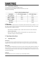
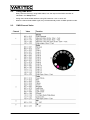
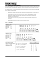
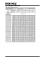
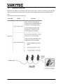
User’s manual
Easy Scan XT3 LED
Table of content
1.
Safety instructions........................................................................................................................... 3
2.
Before you begin............................................................................................................................. 4
2.1.
What is included..................................................................................................................... 4
2.2.
AC Power ............................................................................................................................... 4
3.
Introduction ..................................................................................................................................... 4
3.1.
Features ................................................................................................................................. 4
4.
Product overview ............................................................................................................................ 5
5.
DMX Channel.................................................................................................................................. 6
6.
Setup............................................................................................................................................... 6
6.1.
Light Source ........................................................................................................................... 6
6.2.
Manual focus .......................................................................................................................... 6
6.3.
Fuse replacement .................................................................................................................. 6
7.
Fixture Linking................................................................................................................................. 7
7.1.
Fixture Linking........................................................................................................................ 7
7.2.
DMX Data Cable .................................................................................................................... 7
7.3.
3 pin to 5pin connector........................................................................................................... 8
8.
Mounting ......................................................................................................................................... 8
9.
Operating Instructions..................................................................................................................... 8
9.1.
Operating modes.................................................................................................................... 8
9.2.
Using DMX Mode ................................................................................................................... 9
9.3.
DMX Channel Value............................................................................................................... 9
9.4.
Setting the starting Address ................................................................................................. 10
9.4.1.
examples ..................................................................................................................... 10
9.4.2.
DMX Quick reference chart ......................................................................................... 11
10.
Optional controller .................................................................................................................... 12
11.
Technical data .......................................................................................................................... 13
2 / 14
1. Safety instructions
FOR SAFE AND EFFICIENT OPERATION
Be careful with heat and extreme temperatureAvoid exposing it
to direct rays of the sun or near a heating appliance.
Not put it in a temperature bellow 41°F /5°C, or exceeding 95°F /35°C.
Keep away from humidity, water and dust
Do not place the set in a location with high humidity or lots of dust.
Containers with water should not be placed on the set.
Keep away from sources of hum and noise
Such as transformer motor, tuner, TV set and amplifier.
To avoid placing on un-stable location
Select a level and stable location to avoid vibration.
Do not use chemicals or volatile liquids for cleaning
Use a clean dry cloth to wipe off the dust, or a wet soft cloth for stubborn dirt.
If out of work, contact sales agency immediately
Any troubles arose, remove the power plug soon, and contact with an engineer for repairing,
do not open the cabinet by yourself, it might result a
danger of electric shock.
Take care with the power cable
Never pull the power cable to remove the plug from the receptacle, be sure
to hold the plug. When not using the player for an extended period of time
be sure to disconnect the plug from the receptacle.
3 / 14
2. Before you begin
2.1.
What is included
1 x Easy Scan XT3 LED
1 x Power Cord
1 x Warranty Card
1 x User manual
2.2.
AC Power
This fixture has an auto-switching power supply that can accommodate a wide range of input voltages
(100 V - 240 VAC, 50/60 Hz). Before powering on the unit, make sure the line voltage to which you are
connecting it is within the range of accepted voltages.
Always connect the fixture to a switched circuit. Never connect the fixture to a rheostat
(variable resistor) or dimmer circuit, even if the rheostat or dimmer channel is used only as a
0% to 100% switch.
3. Introduction
3.1.
Features
-
5-channel DMX-512 LED scanner
-
Pan: 180o / tilt: 90
-
Color wheel
11 colors + white
1 quad color, 1 tri color
Rainbow color spin effect
-
Gobo wheel with Gobo shake
14 gobos + open
12 metal, 2 glass installed
Gobo wheel spin effect
Additional Features
-
High-power, 22W (1,360mA) LED
-
Additional power output: max 20 units @ 120V (see manual for details)
-
Built-in automated programs via master/slave
-
Built-in sound activated programs via master/slave
-
Double bracket yoke doubles as floor stand
-
Automatically enters stand alone when no DMX signal is present
4 / 14
4. Product overview
5 / 14
5. DMX Channel
6. Setup
6.1.
Light Source
The fixture does not use a halogen lamp as its light source. Instead, it uses a high luminosity LED,
which comes preinstalled, and does not need to be setup or replaced.
6.2.
Manual focus
To adjust the focus, please follow the instructions below:
1) If operating in stand-alone mode, turn the music down
so that the unit temporarily stops any activity.
2) In DMX control mode, create a static scene with any
gobo of your choice pointed to a flat surface, ideally at a
halfway point of the fixture’s total coverage area.
3) Rotate the manual focus either clockwise or counter-clockwise until the spot is defined by a hard
edge.
6.3.
Fuse replacement
Disconnect the power cord before replacing a fuse and always replace it with the same
type of fuse.
With a flat head screwdriver, wedge the fuse holder out of its housing.
Remove the blown fuse from its holder and replace with the exact same
type of fuse. Insert the fuse holder back in its place and reconnect power.
6 / 14
7. Fixture Linking
7.1.
Fixture Linking
You will need a serial data link to run light shows of one or more fixtures using a DMX-512 controller
or to run synchronized shows on two or more fixtures set to a master/slave operating mode. The
combined number of channels required by all the fixtures on a serial data link determines the number
of fixtures the data link can support.
Fixtures on a serial data link must be daisy chained in one single line. To comply with
the EIA-485 standard no more than 32 devices should be connected on one data link.
Connecting more than 32 fixtures on one serial data link without the use of an optically isolated
DMX splitter may result in deterioration of the digital DMX signal.
7.2.
DMX Data Cable
To link two or more fixtures together you must use DMX compliant data cables.
If you choose to create your own cable, please use data-grade cables that can carry a high quality
signal and are less prone to electromagnetic interference. Use a Belden© 9841 or equivalent cable,
which meets the specifications for EIA RS-485 applications.
Standard microphone cables cannot transmit DMX data reliably over long distances.
The cable must have the following characteristics:
-
Type: shielded, 2-conductor twisted pair
-
Maximum capacitance between conductors: 30 pF/ft.
-
Maximum capacitance between conductor and shield: 55 pF/ft.
-
Maximum resistance: 20 ohms / 1000 ft.
-
Nominal impedance: 100 – 140 ohms
Do not allow contact between the common and the fixture’s chassis ground. Grounding
the common can cause a ground loop, and your fixture may perform erratically. Test
the cables with an ohmmeter to verify correct polarity and to make sure the pins are not
grounded or shorted to each other.
7 / 14
7.3.
3 pin to 5pin connector
A lot of fixtures are still using a 5pole DMX connector.
In this case you can buy a adaptor or built up a connector on your own.
Wiring then is as following:
8. Mounting
It is important never to obstruct the fan or vents pathway. Mount the fixture using, a suitable “C” or “O”
type clamp. Adjust the angle of the fixture by loosening both knobs and tilting the fixture. After finding
the desired position, retighten both knobs.
-
When selecting an installation location, consider ease of access for routine maintenance.
-
Always use safety cables.
-
Never mount the unit in places where it will be exposed to rain, high humidity, extreme
temperature changes or restricted ventilation.
9. Operating Instructions
9.1.
Operating modes
Stand alone
The Stand-alone mode is activated automatically when the fixture does not receive a DMX signal,
regardless of DIP switch settings. The fixture will run through its built in program (sound activated).
Master Slave
The Master/Slave mode will allow you to link up to as many units as you want, without a controller, in a
daisy chain fashion. In this mode, the first unit in the daisy chain will automatically command all other
units following regardless of their DIP switch settings. See the Setup section for instructions on how to
connect the various units.
DMX Mode
This mode allows the unit to be controlled by any universal DMX controller
8 / 14
9.2.
-
Using DMX Mode
Daisy chain the fixture(s), using DMX cables, from the output of the DMX controller as
indicated in the Setup section.
-
Assign the individual DMX address, using DIP switches 1 to 9 on each unit.
-
When the fixtures detect DMX signal, they will automatically switch to DMX operation mode.
9.3.
DMX Channel Value
9 / 14
9.4.
Setting the starting Address
Set the starting address using the group of DIP switches located usually on bottom of the fixture. Each
DIP switch has an associated value. Adding the value of each switch in the ON position will provide
the starting address. The following instructions will help you to figure out which switches to toggle ON
given a specific starting address:
-
Determine the largest value switch that is less than the starting address. Turn this switch on.
-
Subtract the value of the switch you just turned on from the starting address number.
-
Determine the largest value switch that is less than the remainder from the previous
subtraction. Turn this switch on.
-
Subtract the value of the switch you just turned on from the remainder of the previous
subtraction.
-
9.4.1.
Repeat steps three and four until you have a remainder of zero.
examples
10 / 14
9.4.2.
DMX Quick reference chart
11 / 14
10.
Optional controller
Optional it is possible to buy the Easy Scan XT3 remote control. It will be connected by using the jack
input, on the first unit. The other units you want to control together should be connected like a dmx
line.
The functions of the remote control are:
12 / 14
11.
Technical data
13 / 14
Importeur:
B & K Braun GmbH
Industriestraße 1
D-76307 Karlsbad
www.bkbraun.com
[email protected]
14 / 14