1
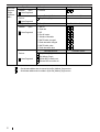
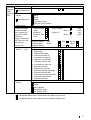
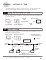
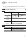
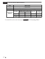
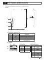
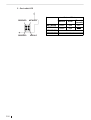
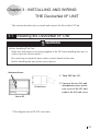
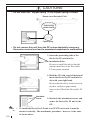
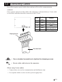
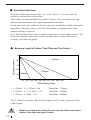
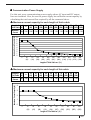
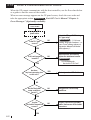
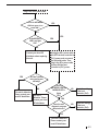
GP-70 Series
I/O Unit
User Manual
PREFACE
Thank you for purchasing Digital's DeviceNet I/F Unit (GP070-DN41) for use with
the GP70 Series panels and which is hereafter referred to as "this unit". This unit
functions as an interface between the < Pro-face® > GP70 Series Graphic Control
Panel, (hereafter referred to as the "GP") , and a DeviceNet system.
This manual contains the information necessary to use a GP to communicate via
DeviceNet system. To ensure the correct use of your GP, each GP70 series unit has
its own User's Manual. Prior to installing this unit in your GP, please read your GP
User's Manual's "CHAPTER 1.1: Operating the GP" (Optionally available).
This unit is compatible with the following GPs :
GP-470 Series, GP-570 Series, GP-675 Series, GP-870 Series, GP-477R Series,
GP-577R Series units.
NOTE:
(1) It is forbidden to copy the contents of this manual, either in whole or in part,
except for the purpose of the user’s personal use, without the express written
permission of the Digital Electronics Corporation of Japan.
(2) The information provided in this manual is subject to change without notice.
(3) This manual has been written with care and attention to detail; however, should
the user discover any errors or omissions, please contact the Digital Electronics
Corporation and inform them of your findings.
(4) Please be aware that Digital Electronics Corporation shall not be held liable by
the user for any damages, losses, or third party claims arising from the uses of
this product.
(5) This unit has received CE marking and is UL approved. Please be aware,
however, that, depending on the user's application of this GP70 series product,
the product's CE marking and UL approval conformity may be lost.
© Copyright 1999, Digital Electronics Corporation. All Right Reserved.
The product names used in this manual are the registered trademarks of their
respective companies.
∗
is a registered trademark of ODVA (Open DeviceNet Vendor
Association).
1
TABLE OF CONTENTS
PREFACE ................................................................................................................................1
TABLE OF CONTENTS ...........................................................................................................2
SAFETY PRECAUTIONS ........................................................................................................3
DEVICE PROFILE ...................................................................................................................4
UL / c-UL(CSA) APPROVAL ...................................................................................................8
CE MARKING NOTES .............................................................................................................8
UNPACKING THE DeviceNet I/F UNIT ...................................................................................9
SYMBOL INFORMATION ........................................................................................................9
Chapter 1 : INTRODUCTION
1.1 Using the DeviceNet I/F Unit ....................................................................................... 1-1
1.2 System Design ............................................................................................................ 1-1
1.3 Screen Editor Program Caution ................................................................................... 1-2
Chapter 2 : SPECIFICATIONS
2.1 DeviceNet Specifications ............................................................................................. 2-1
2.1.1 General Specifications .................................................................................... 2-1
2.1.2 Structural Specifications ................................................................................. 2-1
2.1.3 Performance Specifications ............................................................................ 2-2
2.2 Part Names and Functions .......................................................................................... 2-3
Chapter 3 : INSTALLING AND WIRING THE DeviceNet I/F UNIT
3.1 Installing the DeviceNet I/F Unit .................................................................................. 3-1
3.2 Connecting Cables ...................................................................................................... 3-3
Chapter 4 : Troubleshooting
4.1 Troubleshooting ...........................................................................................................
4.1.1 Problems .........................................................................................................
4.1.2 When a Communication Error Occurs ............................................................
4.2 DeviceNet I/F Unit Check Methods..............................................................................
2
4-1
4-1
4-2
4-4
SAFETY PRECAUTIONS
This manual includes the information that must be followed to operate this product
correctly and safely. Read this manual and attached manuals to thoroughly
understand the correct operation and functions of this product.
Usage of Icons
Throughout this manual, to allow you to use this product correctly, the following
icons are provided next to the operations that require special attention. The
operations described with these icons contain essential safety information. The
following is an example of the icons and their meanings:
Indicates situations where severe bodily
WARNING
!
injury, death or major machine damage can
Warning
occur.
Indicates situations where slight bodily
! CAUTION
injury or machine damage can occur.
Caution
WARNINGS
To ensure the safe and correct use of both this unit and your GP, please observe the
following precautions:
· When attaching this unit to the GP, make sure that the GP's power cord is not
plugged in to the main power (constant), in order to prevent electric shocks.
· Be careful not to touch the surface of this unit's printed circuit board.
· Do not modify this unit in any way, since an electric shock or fire may occur.
· Design your system so that the machine will not malfunction due to a
communication error between the GP and the Host (PLC). Otherwise, there could
be a danger of bodily injury or damage to equipment and/or materials.
To Prevent this unit from malfunctioning :
· Do not allow water, liquid or metallic objects to enter into the unit, since they can
cause the unit to either malfunction or to create an electric shock.
· Please avoid using this unit in areas where sudden, large changes in temperature
may occur. These changes can cause condensation form inside the unit, possibly
causing an accident.
· Avoid installing this unit in an environment where it will be exposed to direct
sunlight, high temperatures or excessive amounts of dust.
· Since this unit is a precision instrument, do not install it where strong impacts or
vibration will occur.
· Avoid installing this unit in an environment where it may be exposed to chemical
vapors.
· Do not use paint thinner or organic solvents to clean the outside of this unit.
Instead, soak a soft cloth in a diluted neutral detergent, wring it tightly, and then
wipe the unit's outside case.
3
DEVICE PROFILE
Device Profile Table
General
Data
DeviceNet
Physical
Conformance
Data
Conforms to DeviceNet Specification
Volume I - Release
Vendor Name
Device Profile Name
Product Name
Product Catalog Number
Product Revision
HMS Fieldbus Systems AB (Hassbjer Micro)
Communications Adapter
AnyBus-S DeviceNet
12
1.2
Network Power Consumption (Max)
0.065 A @ 11V DC (worst case)
Connector Style
Open-Hardwired
X
Sealed-Mini
Open-Pluggable
X
Sealed-Micro
Isolated Physical Layer
LEDs Supported
None
MAC ID Setting
Default MAC ID
Communication Rates Supported
X
Module
Network
X
X
Combo Mod/Net
I/O
DIP Switch
Other
X
Software Settable
DIP Switch
Other
X
Software Settable
500k bit/s
Group 2 Only Client
Group 2 Server
Group 2 Only Server X
Peer-To-Peer
Tool (not a Device)
Group
Group 2
Group 3
Dynamic I/O Message Groups (Peer to Peer)
Group
Group 2
Group 3
Default I/O Data Address Path
Input:
Output:
Fragmented Explicit Messaging Supported
If yes, Acknowledge TimeOut
Service
Service
X
Group 2 Client
UCMM Explicit Message Groups Supported
Typical Target Addresses
Consumption
Production
2
*1
Yes
No
125k bit/s X
250k bit/s X
Device Network Behavior
DeviceNet
Communication
Check All That Apply
Data
4
Volume II - Release
63
Communication Rate Setting
*1
2
Class 4
Class 4
Yes
Inst. 64
Inst. 96
X
Attr.
Attr.
3
3
No
1200 ms
16
14
Class 1
Class 1
Inst. 1
Inst. 1
Attr. 7
Attr. 7
Used the DeviceNet module manufactured by HMS Fieldbus Systems AB
(Hassbjer Micro).
Object Implementation
DeviceNet
Required
Object
Implementation
Object Class
Attributes
Open
None Supported
ID Description
1
2
3
4
Revision
Max instance
Number of Instances
Optional attributes list
Get Set Value Limits
X
5 Optional services list
6 Max Id of class attributes
7 Max Id of instance attributes
DeviceNet Services
Services
Parameter Options
Get_Attributes_All
Reset
None Supported
Object Instance
Attributes
Open
X Get_Attribute_Single
Find_Next_Object_instance
ID Description
1 Vendor
2 Device type
3 Product code
4 Revision
5 Status (bits supported)
6 Serial number
7 Product name
8 State
9 Config. Consistency Value
Get Set Value Limits
X
=(90)
X
=(12)
X
=(12)
X
=(1.2)
X
X
X
X
10 Heartbeat Interval
DeviceNet Services
Services
AnyBus-S DeviceNet
Parameter Options
Get_Attributes_All
X Reset
0,1
X Get_Attribute_Single
Set_Attribute_Single
X
Get indicates attribute value is returned by the Get_Attribute_Single service.
X
Set indicates attribute value is written to by the Set_Attribute_Single service.
5
Object Class
DeviceNet
Required
Object
Implementation
Attributes
Open
None Supported
ID Description
1 Revision
Get Set
X
DeviceNet Services
Services
None Supported
Object Instance
Attributes
Open
None Supported
Parameter Options
X Get_Attribute_Single
ID Description
1
2
3
4
5
6
7
8
9
MAC ID
Baud rate
BOI
Bus-off counter
Allocation information
MAC ID switch changed
Baud rate switch changed
MAC ID switch value
Baud rate switch value
Get Set
X
X
X
X
X
None Supported
6
X
X
X
X
Value Limits
X
X
DeviceNet Services
Services
Value Limits
Get_Attribute_Single
Set_Attribute_Single
Allocate M/S connection set
Release M/S connection set
X
Get indicates attribute value is returned by the Get_Attribute_Single service.
X
Set indicates attribute value is written to by the Set_Attribute_Single service.
Parameter Options
DeviceNet
Required
Object
Implementation
Object Class
Attributes
Open
None Supported
Services
None Supported
Object Instance
Complete the Object
Instance sectionfor
each Instance type
supported. Indicate
Production
trigger,Transport type
and Transport Class
supported for
Dynamic I/O.
Attributes
Services
X
X
Open
ID Description
1 Revision
Get Set
X
Value Limits
DeviceNet Services
Parameter Options
Reset
Create
Delete
X Get_Attribute_Single
Find_Next_Object_Instance
Predefined M/S Connections Peer to Peer Connections
Max Instances
Explicit Message
Explicit Message
Total
Client
Polled
Server
X
Bit Strobed
Dynamic I/O
Total
Client
Change of State
Server
Cyclic
Production trigger(s) Cyclic
Transport type(s)
Server
Transport class(es)
ID Description
1 State
2 Instance type
3 Transport Class trigger
4 Produced connection ID
5 Consumed connection ID
6 Initial comm. characteristics
7 Produced connection size
8 Consumed connection size
9 Expected packet rate
12 Watchdog time-out action
13 Produced connection path length
14 Produced connection path
15 Consumed connection path length
16 Consumed connection path
17 Production inhibit time
DeviceNet Services
X Reset
Delete
Apply_Attributes
X Get_Attribute_Single
X Set_Attribute_Single
COS
2
App. trig.
Client
3
Value Limits
Get Set
X
X
X
X
X
X
X
X
X X
X
X
X X
X
X X
X
Parameter Options
Get indicates attribute value is returned by the Get_Attribute_Single service.
Set indicates attribute value is written to by the Set_Attribute_Single service.
7
UL / c-UL(CSA) APPROVAL
The GP070-DN41 is a UL/ c-UL(CSA) listed product. (UL File No.E182139).
The GP070-DN41 conforms as a component to the following standards:
• UL 508
Industrial Control Equipment.
• UL 1604
Electrical Equipment for Use in Class I and II, Division 2, and Class III Hazardous
(Classified) Locations.
• CAN / CSA-C22.2, Nos. 142, and 213-M1987
Standard for Safety of Information Technology Equipment, including Electrical
Business Equipment.
GP070-DN41 (UL registration No.:2780041)
• Be sure that the unit is installed so that it is at least 100 mm away from any adjacent
structures or devices. If these requirements are not met, the heat generated by the
unit's internal components may cause the unit to fail to meet UL standard
requirements.
UL 1604 Compliance Conditions and Handling Cautions
1. Power, input and output (I/O) wiring must be in accordance with Class I, Division 2
wiring methods, Article 501-4 (b) of the national Electrical code, NFPA 70 or as
specified in Section 10-152 of the Canadian Electrical Code for installations within
Canada and in accordance with the authority having jurisdiction.
2. Suitable for use in Class I, Division 2, Groups A, B, C and D hazardous location, or
nonhazardous location only.
3. WARNING: Explosion hazard - substitution of components may impair suitability for
Class I, Division 2.
4. WARNING: Explosion hazard - do not disconnect equipment unless power has been
switched off or the area is known to be nonhazardous.
5. WARNING: Explosion hazard - when in hazardous locations, turn off power before
replacing or wiring modules.
CE MARKING NOTES
The GP070-DN41 is a CE marked, EC compliant product. It complies with EN55011
class A, EN50082-2.
8
UNPACKING THE DeviceNet I/F UNIT
The DeviceNet I/F package should include the following items:
• DeviceNet I/F Unit
• GP70 series DeviceNet I/F Unit
(GP070-DN41)
User's Manual (this manual)
(Installed with attachment screws)
GP70 series
DeviceNet
I/F Unit
User's Manual
This unit has been carefully packed, however, should you find any item to be either
damaged or missing, please contact your local GP distributor immediately for service.
SYMBOL INFORMATION
The terms and symbols used in this manual are described below.
SCREEN EDITING
PROGRAM
PLC
Designates Digital's "GP-PRO/PB III for Windows"
screen editor program.
Abbreviation for Programmable Logic Controller
Important
Failure to observe this instruction may cause abnormal
operation of equipment or data loss.
Note:
Provides hints on correct use, or supplementary information.
Reference
Indicates related (manual name, page number) information.
1, 2, ...
Describes an operating procedure. Be sure to perform
the specified operations in the order written.
!
*1
Indicates terms or data further explained in a footnote.
9
10
Chapter 1 : INTRODUCTION
This chapter describes the function of the DeviceNet I/F Unit and the precautions
necessary when using the GP to perform DeviceNet data communication.
1.1 Using the DeviceNet I/F Unit
This unit enables your GP to be directly connected to an DeviceNet-compatible PLC
or personal computer *1.
DeviceNet
Cable
Direct Connection
or
Personal computer
DeviceNet
I/F Unit
DeviceNet-compatible PLC
GP
1.2 System Design
Be sure all connections conform to DeviceNet communication standards. Refer to the
connection example shown below.
Personal computer
DeviceNet-compatible PLC
< Conforms to DeviceNet
communication standards>
or
: T - Port Tap
Communication
Power Supply
Trunk Line
Trunk Line
Terminating
Resistor
≈
Terminating
Resistor
Power Supply Tap
Drop Line
Drop Line
○
○
○
○
Drop Line
○
○
○
○
○
○
○
○
○
○
○
○
○
○
○
DeviceNet
I/F Unit
maximum of 63
slaves
(Maximum number of connectable nodes is 64)
*1 The number of compatible PC types may be limited.
1-1
1.3 Screen Editor Program Caution
When using the screen editor to designate the PLC's type, be sure to select
"DeviceNet Slave I/O".
For PLC type selection details, refer to your screen editing program's Operation
Manual (included with the software).
Note:
1-2
• To use the DeviceNet I/F Unit (GP070-DN41), the "GP-PRO/PB III for
Windows Ver.3.0 (or later)" software is required. When using versions
of GP-PRO/PB III that are earlier than that, please contact your local
GP distributor for information.
Chapter 2 : SPECIFICATIONS
This chapter describes the specifications, part names, and external dimensions of the
DeviceNet I/F Unit.
2.1 DeviceNet Specifications
2.1.1
General Specifications
Item
Power Supply
Specification
I/F Unit Power Supply (supplied Communication Power Supply
from GP unit)
(supplied from Network)
DC5V +/-5%
DC11V to DC25V
3W or less
Power Consumption
Operating Temperature
and Humidity
2.5W or less
o
0 to 50 C / 20 to 85 %RH (not higher than the temperature or
humidity of the connected GP unit)
Storage Temperature and
o
-10 to 60 C / 20 to 85 %RH (no condensation)
Humidity
Vibration Resistance
Operating Atmosphere
2
10 to 25 Hz (19.6m/s in X, Y, and Z directions for 30 minutes each)
Free from corrosive gas
2
Grounding
2.1.2
Use a grounding resistance of less than 100Ω and a 2mm or
thicker wire, or your country's applicable standard.
Structural Specifications
Item
Usage
Power Consumption
Weight
Cooling system
Specification
Installed in large-sized GP's rearface expansion board slot
167 (W) x 115 (H) x 21.2 (D) mm
(DeviceNet unit only, not including projections and gasket.)
approx. 300g
Natural air circulation
2-1
2.1.3
Performance Specifications
Item
Specification
Connector
Screw Connector
I/O
Conforms to DeviceNet communication standards
Baud Rate
125K / 250K / 500Kbps (via changeover switch)
Transmission
Distance
Baud Rate
Maximum Length of Trunk Line
Total Drop
Line Length
Thick Cable
Thin Cable
500Kbps
100m or less
100m or less
6m or less
39m or less
250Kbps
250m or less
100m or less
6m or less
78m or less
125Kbps
500m or less
100m or less
6m or less
156m or less
For detailed DeviceNet cable information,
2-2
Drop Line
Reference
"3.2 Connecting Cables".
2.2 Part Names and Functions
The name and function of each item is explained below.
(Unit:mm)
167
11.4
A
B
C
115
1
A : DeviceNet Connector Pins
Pin No.
Wire Cover Color
Comment
1
2
3
4
5
Black
Blue
No Cover
White
Red
Power Supply (V-)
Communication Data [Low side] (CAN_L)
Shield
Communication Data [High side] (CAN_H)
Power Supply (V+)
B : DIP SW
B/R
ADDR.
B/R (Baud Rate)
ADDR. (Node Address)
Baud Rate
DIP SW (1,2)
ON
125K
00
OFF
250K
500K
Reserved
01
10
11
1 2 3 4 5 6 7 8
Address DIP SW (3 to 8)
0
000000
1
000001
2
000010
::
::
::
::
61
111101
62
111110
63
111111
2-3
C : DeviceNet LED
RESERVED
NETWORK
NETWORK
MODULE
RESERVED
2-4
MODULE
Network Status
Cannot
Normal
Error
Transmit
Green
Red
OFF
Green
Red
RESERVED
Not Used
RESERVED
Not Used
Chapter 3 : INSTALLING AND WIRING
THE DeviceNet I/F UNIT
This section describes how to install and connect the DeviceNet I/F Unit.
3.1 Installing the DeviceNet I/F Unit
WARNING
Before Installing This Unit
· Make sure that power is not being supplied to the GP when installing this unit, in
order to prevent electric shocks.
· Be careful not to touch the inner surface (circuit board) of this unit.
Before installing this unit, please put on gloves.
Attachment Screws
1. Turn OFF the GP.
I/O Unit Cover
2. Unscrew the two I/O unit
attachment screws on the
rear cover of the GP, and
remove the I/O unit cover.
Rear of GP
* This diagram uses a GP-470 series unit.
3-1
CAUTIONS
• Do not touch the "copper spring" or the copper spring's contact.
Bottom view of DeviceNet I/F Unit
Copper spring
contact location
Copper spring
• Do not remove this unit from the GP unless absolutely necessary.
Excessive removal can lead to premature breakdown or malfunction.
3. Insert the protruding tabs of the
DeviceNet I/F unit into the
installation holes.
Be sure to install the unit so that the
smooth metal face of the DeviceNet
I/F unit points outward.
4. Hold the GP with your left hand and
insert the DeviceNet I/F unit into its
slot with your right hand.
Be sure that the unit is seated correctly
in place, so that no gaps remain
between the GP and the DeviceNet I/F
unit.
Attachment
Screws
Note:
3-2
5. Reattach the attachment screws and
secure the DeviceNet I/F unit to the
GP.
• To install the DeviceNet I/F unit in a GP-870 series unit, it must be
inserted vertically. The attachment procedure , however, is the same
as shown above.
3.2 Connecting Cables
DeviceNet requires special cables that conform to DeviceNet communication
standards.
First, connect each wire of the cable to the connector, as shown below (a 5-wire cable
is used here) and then attach the connector to the I/F unit.
1
Wire Cover
Color
Black
2
Blue
3
None
4
White
5
Red
Pin No.
Comment
Power Supply (V-)
Communication Data
[Low side] (CAN_L)
Shield
Communication Data
[High side] (CAN_H)
Power Supply (V+)
Clamping Screws
5
4
3
1 2
DeviceNet Cable
!
• Use a standard screwdriver to tighten the clamping screws.
Important
Note:
• Do not solder cable wires to the connector.
When using 3-wire cables
• Connect these wire to the communication and shield pins only.
• Use separate cables as slave-to-slave power-supply lines.
3-3
DeviceNet Cable Types
DeviceNet cables use contain either 3 or 5 wires. These 3- or 5-wire cables are
available as either thick or thin cables.
Thick cables are hard and difficult to handle. However, they are suitable for longdistance communications since signal degradation is minimal.
On the other hand, thin cables are flexible and easily handled but exhibit more signal
degradation. Therefore, they are used for short-distance communications where
complex cabling is required.
Also, thick and thin cables, can be combined together to create a single network. The
maximum length of cables (total of thick and thin cables) can be calculated by
refering to the following graph.
Maximum Length of Cables (Total Thick and Thin Cables)
Thin Cable (unit m)
10
125kbps
80
60
40
20
0
250kbps
500kbps
50
100 150 200 250 300 350 400 450 500
Thick Cable (unit:m)
• L (Thick) + 5 × L (Thin) = 500
Baud Rate : 125kbps
• L (Thick) + 2.5 × L (Thin) = 250
Baud Rate : 250kbps
• L (Thick) + L (Thin) = 100
Baud Rate : 500kbps
The "L (Thick)" represents "Thick Cable Length" and "L (Thin)" represents "Thin
Cable Length."
!
Important
3-4
• Between a trunk and a drop line, do not mix 3-wire and 5-wire
cables. Use only one type of cable.
Communication Power Supply
For this unit, use a communication power supply whose AC input and DC output
lines are insulated. Also, be sure the power supply has sufficient current capacity by
calculating the total current flow required by all the connected slaves.
Maximum current capacity for each length of thick cable
Maximum Current Capacity (A)
Length of (m)
0
Thick Cable ( ft )
Maximum
(A) 8.00
Current
25
(82)
50
100 150 200 250 300 350 400 450 500
(164) (328) (492) (656) (820) (984) (1148) (1312) (1476) (1640)
8.00
5.42
2.93
2.01
1.53
1.23
1.03
0.89
0.78
0.69
0.63
9
8
7
6
5
4
3
2
1
0
0
25
(82)
50
(164)
100
(328)
150
(492)
200
(656)
250
(820)
300
350
400
450
500
(984) (1148) (1312) (1476) (1640)
Length of Thick Cable m / ( ft )
Maximum current capacity for each length of thin cable
Maximum Current Capacity (A)
Length of (m)
0
Thin Cable ( ft )
Maximum
(A) 3.00
Current
10
(33)
20
(66)
30
(98)
3.00
3.00
2.06
40
50
60
70
80
90
100
(131) (164) (197) (230) (262) (295) (328)
1.57
1.26
1.06
50
(164)
60
(197)
0.91
0.80
0.71
0.64
4
3
2
1
0
0
10
(33)
20
(66)
30
(98)
40
(131)
70
(230)
80
(262)
90
(295)
100
(328)
Length of Thin Cable m / ( ft )
3-5
!
Important
• Be sure your power supply is in excess of that required by all
the units on the network.
• Be sure to choose a power supply with sufficient capacity, and
take into account elements such as the amount of rush current
during startup. Also, set up a fail-safe mechanism to protect
against short circuits or other malfunctions.
• Use a dedicated communication power supply for this unit. Do
not connect any other equipment to it.
Note:
3-6
• We recommend you consult with an authorized agent when preparing
DeviceNet connections.
Chapter 4 : TROUBLESHOOTING
4.1 Troubleshooting
This section describes how to find and solve I/F problems that may occur.
4.1.1
Problems
During operation of the GP, the following problems may occur:
• Communication Errors.
• GP/HOST Controller communication link is disrupted.
The troubleshooting flow charts for these problems are shown on the following
pages.
WARNING
Prior to Troubleshooting the I/F Unit
• When connecting the I/F Unit's data transfer cable, make sure that the
GP's power cord is disconnected, to prevent electric shocks.
Note: • The problems described in this section are assumed to be attributable
to the GP, not to the host controller (PLC). For host controller
problems, refer to troubleshooting guide included in the manual for
your host controller (PLC).
4-1
4.1.2
When a Communication Error Occurs
When the GP cannot communicate with the host controller, use the flow chart below
as a guide to find the cause of the trouble.
When an error message appears on the GP panel screen, check the error code and
take the appropriate action. Reference Each GP User's Manual "Chapter 4 Error Messages" (Optionally available).
Communication
error occurs
Unplug the GP's
power cable.
Is the PLC type
correct ?
NO
YES
Is this unit properly
inserted ?
NO
Insert this unit, and securely
tighten the attachment screws.
Reference
"3.1 Installing the
DeviceNet I/F Unit"
YES
Are there
any bent connector pins
on this unit ?
Select the " Target PLC" during
PLC type setup.
Reference
"1.3 Screen
Editing Program Cautions" or
your screen editing software's
Operation Manual (included
with software)"
YES
Contact your local GP distributor.
NO
Are the DeviceNet
setup conditions
correct ?
NO
Designate the correct setup
conditions.
YES
Are the
DeviceNet Connections
correct ?
YES
4-2
NO
Properly connect all DeviceNet
cables, and secure all DeviceNet
connectors.
Plug in the GP's power cable.
Does the NETWORK
LED flash green, then
remain ON ?
YES
NO
YES
Is the MODULE
LED's red light
ON ?
YES
NO
Contact your local GP
distributor about replacing
this unit.
YES
Unplug the GP's power cable,
turn OFF the host controller's
(PLC) power, and re-connect
the DeviceNet cable. Then,
plug in the GP's power cable
and turn ON the host
controller's (PLC) power.
Is Data Transfer
being performed
normally?
NO
This unit is defective.
Please contact your
local GP distributor.
The GP is
defective. Please
contact your local
GP distributor.
Are the
NETWORK LED and
MODULE LED's
lights
ON ?
NO
Check the settings
of the host
controller (PLC).
YES
Does the selfdiagnosis program
detect an error?
NO
Check the settings
of the host
controller (PLC).
YES
This unit is defective.
Please contact your
local GP distributor.
4-3
4.2 DeviceNet I/F Unit Check Methods
GP Self-Diagnosis
The GP provides a self-diagnosis program to check whether or not the GP's system
and its interface are operating normally. If a DeviceNet communication error occurs,
activate the self-diagnosis program, using the steps below.
1. Insert the DeviceNet I/F unit into the GP.
2. Change the GP to "OFFLINE MODE" and select " B * Communication Check"
from the GP's self-diagnosis menu.
3. The Communication Check will start.
If this unit is operating normally, "OK" appears. If an error is found, the
corresponding error message appears.
For self-diagnosis menu and details concerning other self-diagnosis functions,
Reference
Each GP's User's Manual (Optionally available)
Checking the LED Indicators
Turn ON the GP.
The MODULE and NETWORK LED, initially are both green, then change to red in
sequence. If the MODULE LED changes to green again after this, this unit is
operating normally. When this unit is connected to a Network, communication is
occurring normally if the NETWORK LED blinks (green) for a few seconds and then
stays lit.
4-4


![Rockwell (Allen-Bradley) PLCs [Ethernet Communication] - Pro](http://vs1.manualzilla.com/store/data/005902559_1-37f0d35b01d224110d582dd04f222df0-150x150.png)