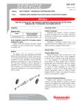
1
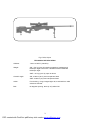
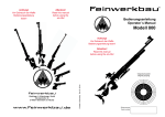
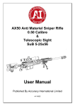
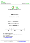
MODEL AW SNIPER 7.62 x 51
SNIPER RIFLE
USERS MANUAL
Accuracy International Limited
P.O. Box 81 Portsmouth
Hampshire, England PO3 5SJ
Telephone: +44 (023) 9267 1225
Fax: +44 (023) 9269 1852
E-mail: [email protected]
VAT No. GB 430-6893-46
BS EN ISO 9001 (1994)
NATO Supplier No: U 4393
PDF created with FinePrint pdfFactory trial version www.pdffactory.com
TABLE OF CONTENTS
PARA
CONTENTS
PAGE
Table of Contents
Technical Specification
Introduction
General Description
Safety Features
Safe Handling instructions
Operating Instructions
1
3
5
5
5
7
7
1
Safety Precautions
7
2
2A
A1
A2
A3
A4
2B
2C
2D
2E
2F
2G
2H
2I
2J
2K
2L
2M
2N
2O
Assembling and Stripping the Rifle
Assembling
Bipod
Sight/Mount
Bolt
Magazine
Setting up the Rifle
Loading
Firing and operating the Bolt
Reloading
Unloading
To Unload a live Cartridge
Zeroing the Rifle
Zeroing Check List
Field Stripping
Additional Stripping and Assembling
To Strip the bolt
Re-Assembly of Bolt
Stripping the Magazine
Tests after Re-Assembly
8
8
8
8
8
9
9
10
11
12
12
12
13
14
15
15
16
16
16
17
3
3A
3B
3C
3D
3E
3F
Telescopic Sight
Eye Relief Adjustment
Elevation and Windage
Technical Details of AW’s 3-12x50 Sight
Iron Sights (when supplied)
Zeroing (disc type iron sights)
Zeroing (‘flip up’ blade type iron sights)
17
18
18
19
20
20
22
4
5
6
7
8
9
10
11
12
13
14
Bipod Adjustment and Use
Butt length Adjustment
Cleaning and Lubricating Instructions
Care after Firing
Inspection
Cleaning the Telescope
Accuracy and Ammunition
User Tips
Exterior Ballistic Data
Torque Settings for AW Rifle
Supplement for Weapons fitted with a Suppressor Unit
22
23
23
25
25
25
25
26
27
28
28
1
PDF created with FinePrint pdfFactory trial version www.pdffactory.com
FIG NO
CONTENTS
PAGE
1
2
3
4
5
6
7
8
9
10
11
12
13
14
15
16
Rifle, Sniper
Safe/Fire Mechanism
The Bolt
Setting Up the Rifle
Loading
Unloading
Removing the Bolt
Removing the Firing Pin and Shroud Assembly
Stripping the Magazine
Telescopic Sight
Reticle Pattern
Rearsight Disc Type Iron Sights
Foresight
Rearsight ‘flip up’ Blade Type Iron Sights
Butt Length Adjustment
Transit Case and Accessories
3
6
9
9
10
12
15
16
17
17
19
21
21
22
23
29
2
PDF created with FinePrint pdfFactory trial version www.pdffactory.com
Fig 1 Rifle, Sniper
TECHNICAL SPECIFICATION
Calibres:
7.62 x 51 NATO (.308 Win)
Weight:
AW = 5.9 kg (13.0 lb) including magazine, handstop and
telescopic sight mount with 3-12x50 Schmidt und Bender
telescopic sight
AWP = 6.5 kg (14.3 lb), spec as above
Overall Length:
AW 1178mm (46.4”) two butt spacers fitted
AWP 1120mm (44”) two butt spacers fitted
Action:
Front locking, 3 lugs, integral sight rail, machined from solid
ordnance steel bar
Bolt:
60 degrees opening, 6mm (0.24”) striker fall.
3
PDF created with FinePrint pdfFactory trial version www.pdffactory.com
Trigger:
2 stage, adjustable, set at 1.8 kg (4lbs)
NOTE:
Mechanisms optimised against dirt and ice
Barrel:
Stainless matchgrade, 1-10, 11 & 12 twist. AW 26” with muzzle
brake, AWP 24” long
Safety:
3 way ‘safe’ blocks the firing pin and locks bolt in closed position.
Middle position ‘safe’ blocks the firing pin, but bolt can be
manipulated. The safety can only be applied when rifle is cocked
Stock:
Alloy chassis enclosed by scuff resistant, reinforced nylon stock
sides and fitted with 5 sling loops, adjustable butt spacers and
universal bipod
Magazine:
Detachable box type containing 10 rounds
Sights:
Powers : 6 or 10x42 or variable 3-12x50. Type : Military
environmentally sealed for extreme conditions, fitted with large
windage and elevation drums clearly marked and incorporating
click adjustment. Standard AI reticle is a special Mil Dot with
range finder
Mount & Sight:
1 piece, integrated part of sight/rifle ensuring robust connection
and no shift of zero
Bipod:
Universal, quick detachable and folding. Provides 10 degrees loll
either side of upright (alloy or steel head options)
Quality:
Produced and designed to ISO 9001 QA level using the best
materials for highest quality interchangeability and longevity
Usage:
Designed for all uses up to and including military use in roughest,
dirtiest conditions and environmental extremes
Maintainability:
User and armourer maintenance simplicity with complete
interchangeability of ALL parts
Sling Points:
Five sling points fitted (optional extra swivel on handstop)
Performance:
See tables of Page 27
4
PDF created with FinePrint pdfFactory trial version www.pdffactory.com
INTRODUCTION
USERS: YOU MUST READ THIS
MANUAL BEFORE USING THE RIFLE
AND EQUIPMENT DESCRIBED
THE ACCURACY INTERNATIONAL MODEL AW / AWP SNIPER RIFLE is Accuracy
International’s (AI’s) second generation sniper rifle and is the culmination of 10 years
development. Uniquely, the ‘AW’ system and the PM / L96 before it, are ongoing
developments of a completely fresh approach to the sniper’s rifle. The AW’s features address
directly the priorities of design and function required by the sniper and satisfactorily solve the
inherent problems with all conversions of sporting or assault rifles used for sniping.
The ‘AW’ and ‘AWP’ systems have been designed around the 7.62x51 NATO (.308 WIN) and
.243 WIN cartridge. Because precision is only as good as the ammunition, accuracy can
be optimised by the use of suitable match grade ammunition.
GENERAL DESCRIPTION
The AW / AWP sniper rifle is built around a ‘chassis’ system. The receiver body is bolted and
bonded to the magazine housing completely removing any interface and greatly stiffening the
barrel support. All other parts can be removed from these two basic components, simply, with
the barest minimum of tools.
The reinforced nylon stock sides are bolted to the chassis which add greatly to the strength of
the system and make for a comfortable, ergonomic handhold.
The rifles are supplied as standard with integrated one piece telescopic sight mounts, multi
adjustable bipod, handstop, detachable 10 shot box magazine, 5 sling loops, stainless steel
match grade barrel, butt length spacers and ambidextrous reinforced nylon scuff resistant
stock.
Optional accessories include a multi adjustable butt plate, adjustable cheekpiece, adjustable
handstop/bipod mount, butt spike and emergency iron sights.
Optics normally fitted are 6x42, 10x42 and 3-12x50 military grade sights incorporating AI’s
special range finding Mil Dot reticle and military ranging and wide drums.
5
PDF created with FinePrint pdfFactory trial version www.pdffactory.com
SAFETY FEATURES
The AW sniper rifle bolt has three forward locking lugs and one emergency lug at the rear.
The firing pin cannot protrude from the front of the bolt face unless the bolt handle is in the
fully closed position.
Gas leakage from the rear of the action body is minimised by a tight fitting bolt, an action body
with very few ports and bolt shroud at the rear to deflect any gases that get this far, away from
the firers face.
The rifle is fitted with a two stage adjustable trigger which gives a fine let off and through
increased sear engagement, increased safety from accidental discharge by bolt slamming or
droppage of the rifle. The cartridge case head is enclosed by the bolt.
THE SAFETY CATCH (Fig 2)
a) Locks the bolt handle in the closed position.
b) Withdraws and physically blocks the firing pin, so that the rifle is safe during a severe
jar or drop.
In addition, the safety catch cannot be applied unless the rifle is cocked indicating an
empty chamber.
c) The safety catch has 3 modes of operation:
FIRST SAFE The firing pin is physically blocked and withdrawn, but the bolt is free to
be used to unload magazine
SECOND SAFE The firing pin is physically blocked and withdrawn, but the bolt is
locked in closed position
FIRE
NOTE When moving safety catch from the FIRE position to FIRST SAFE POSITION, go
through FIRST SAFE position to SECOND SAFE position, then push safety catch
forward to the FIRST SAFE position.
SAFETY CATCH SET TO
FIRST SAFE POSITION
SAFETY CATCH SET TO
SECOND SAFE POSITION
FIG 2. SAFE / FIRE MECHANISM
6
PDF created with FinePrint pdfFactory trial version www.pdffactory.com
SAFETY CATCH SET TO
FIRE POSITION
SAFE HANDLING INSTRUCTION
1. Always Check the rifle is unloaded when first handling your own (or another persons
rifle), by opening the bolt and physically inspecting the chamber and magazine.
2. Always have the rifle’s bolt open or removed when it is being carried, or when it is
between exercises.
3. Before firing the rifle, always remove the bolt and check the bore is not obstructed.
4. If a muzzle brake, flash hider or suppressor is fitted ensure that the unit is tight and
not clogged or obstructed before use.
5. If the rifle is loaded and cocked ready for use without an immediate target ensure that
the safety catch is FULLY APPLIED, ie fully rearward to SECOND SAFE position
(about 110 degrees from the off position).
NOTE: The resistance felt at the centre of the safety catch movement is the
beginning of the withdrawal of the firing pin from the sears and the safety catch must
be FULLY APPLIED before the rifle is on full safe with bolt handle locked in closed
position.
6. When operating the bolt ALWAYS FULLY CYCLE ie completely open and close the
bolt every time the bolt is manipulated (whether or not you think you have picked up
the next round from the magazine).
7. The safety catch is only operable when the action is cocked.
Warning … Do not fire the rifle if the serial numbers of the action body,
bolt and shroud disagree
Verify cartridge headspace is within limits and safety mechanism is
working properly
OPERATING INSTRUCTIONS
1. SAFETY PRECAUTIONS
Before attempting any operation with the rifle, ensure that it is unloaded AND POINTING
IN A SAFE DIRECTION and safe to handle by carrying out the safety precautions
detailed in the following sub paragraphs.
1.1
1.2
1.3
1.4
1.5
1.6
1.7
1.8
Point the rifle in a non dangerous direction.
Remove the magazine from the rifle.
Raise the bolt handle and slide bolt fully to rear.
Check chamber and magazine are clear of ammunition.
Leave bolt open or remove whilst handling rifle.
Close bolt.
Replace magazine.
APPLY SAFETY CATCH FULLY.
7
PDF created with FinePrint pdfFactory trial version www.pdffactory.com
2. ASSEMBLING AND STRIPPING THE RIFLE
2A Assembling
Rifles are normally delivered to customers complete in their transit case in which instance
he stripping instructions should be read before the assembly instructions. If, however, the
rifles are broken down for transport without a transit case then the following instructions
should be followed:
A1
Bipod
Fit the bipod by inserting the spigot on the bipod into the socket at the front of the rifle
forend. The rifle can now be turned over and the bipod feet put on a flat surface while
the other parts are fitted. The bipod can easily be removed by pushing the release
button under the forend and withdrawn.
A2
Sight/Mount
Install the sight/mount unit by first ensuring that the mount base tightening screws are
sufficiently loose to allow the clamping bar to move outward enough to enable the
complete unit to be rolled on to the sight rail from the left side, on top of the action
body.
Locate the recoil pin in the base of the mount. With this towards the muzzle, place
the mount on top of the action body with the recoil pin in a position adjacent to one of
the two special recoil ‘pockets’ on top of and at the front of the receiver sight rail. The
sight mount assembly should roll on when the recoil pin enters the recoil pocket.
Ensure that the action rail and sight mount are clean prior to assembly.
BEFORE TIGHTENING THE SCREWS PUSH THE SIGHT TOWARDS THE
MUZZLE SO THAT THE RECOIL PIN RESTS AGAINST THE FRON EDGE OF THE
RECOIL POCKET.
FAILURE TO DO THIS MAY RESULT IN DAMAGE TO THE RECOIL PIN
Whilst holding the sight in this position tighten the screws. If the sight is always fitted
in this way there will be no loss of zero during removal and replacement.
Note: Failure to push the pin to the front of the pocket and/or failing to tighten
screws sufficiently may result in damage to the recoil pin and/or sight mount
A3
Bolt (Fig 3)
Before installing the bolt, ensure the shroud is in the position on the bolt body, ie the
nib of the cocking piece is located in the small close fitting indent at the top of the
cocking cam at the rear of the bolt body. The bolt cannot be replaced in the receiver
if the shroud is incorrectly positioned – see sketch.
8
PDF created with FinePrint pdfFactory trial version www.pdffactory.com
If the shroud is loose and the nib is at the bottom of the cocking cam, take the bolt
body in the left hand and with the left thumb depress the bolt location pin. With the
right hand holding the shroud, rotate the shroud 60 degrees clockwise until the
cocking piece slides up the cam and locates in the indent at the top of the cam – with
an audible click (it can be easily felt). The bolt is now ready for placement in the rifle.
BOLT HANDLE
GAS ESCAPE HOLE
LOCKING LUGS
FIRING PIN
SHROUD
EJECTOR
COCKING CAM
COCKING PIECE
EXTRACTOR
BOLT BODY
FIG 3. THE BOLT
To insert the bolt in the receiver body, depress the bolt catch on the left side of the
receiver body with the left thumb and holding it thus, slide the bolt gently into the
receiver. When the bolt is half way in, the thumb bolt catch can be released. The
bolt then should be slightly rotated back and forth to make sure the catch has located
in the bolt groove that runs down the left hand side of the bolt body. The bolt can
then be fully operated.
Apply the safety catch to FIRST SAFE position.
A4
Magazine
The box magazine can be inserted by locating it into the opening underneath the rifle
and pushing all the way home until the catch engages, which can be both heard and
felt. Releasing the magazine for loading cartridges is by pressing the catch in front of
the trigger guard with the right thumb and with the fingers of the right hand pulling the
magazine clear.
2B
Setting up the Rifle – To set up the rifle (Fig 4)
B1
B2
B3
B4
Adopt the prone firing position
Adjust the bipod legs to suit terrain
Fully open the bolt
Place the cheek on the stock, just touching bolt shroud
FIG 4. SETTING UP THE RIFLE
9
PDF created with FinePrint pdfFactory trial version www.pdffactory.com
B5
Check and if necessary adjust the position of the telescopic sight to obtain
the correct eye relief (factory set whenever possible).
B6
Adjust the butt length by adding or subtracting butt spacers to suit the size of
the firer.
FIRING THE RIFLE
CAUTION:
2C
Before firing the rifle ensure that solvent, oil or grease has been removed
from the bore. Always use a rod or pull through from the receiver end to
avoid damage to muzzle. Use the rod and rod guide whenever possible.
Loading – To load the rifle (Fig 5)
FIG 5. LOADING
C1
Place a full magazine into the magazine housing
C2
Push the magazine fully upwards until the magazine retaining catch engages
the lug on the magazine.
C3
Open the bolt by raising the bolt handle and pulling it to the rear.
C4
Feed a round from the magazine into the chamber, by sliding the bolt
forward.
ALWAYS CLOSE THE BOLT FULLY
WARNING : FAILURE TO FULLY CLOSE THE BOLT EVERYTIME THE BOLT IS
MANIPULATED, COULD RESULT IN A LIVE ROUND BEING LEFT IN THE
CHAMBER. THE EXTRACTOR DOES NOT ENGAGE THE RIM OF THE
CARTRIDGE UNLESS THE BOLT IS FULLY CLOSED
10
PDF created with FinePrint pdfFactory trial version www.pdffactory.com
NOTE: If the magazine is over loaded, it will be difficult to get the magazine to engage with
the bolt closed and to strip off the first round.
The rear end of the firing pin protrudes through the rear of the bolt shroud to act as a
cocking indicator when the action is cocked (primed).
C5
2D
APPLY THE SAFETY CATCH IF NECESSARY
Firing and Operating the Bolt – Sequence of Operations
The following sequence will be of assistance when firing and operating the rifle.
D1
Adjust eye piece parallax setting to bring reticle and target into sharp focus.
D2
Set range and windage on sight.
D3
Set the safety catch to FIRE and push the rifle firmly into the bipod using the
shoulder (to pull back on the bipod can cause vertical stringing of shots
especially on soft ground).
D4
Ensure correct aim and operate the trigger.
D5
Follow through and observe target.
NOTE: The following procedure minimises the movement of the rifle and body during
the firing sequence (right handed firers only).
D6
Remain in the aim position during re-cycling.
D7
Place the thumb on the action or shroud and grasp the bolt with the fingers of
the right hand.
D8
Bring the fingers towards the thumb. If any resistance is felt during initial
unseating of the fired case (primary extraction) increase the upward pressure
on the bolt handle with the fingers.
D9
Pull the bolt all the way rearward to allow ejection of the fired case and pickup
of next round.
WARNING
D10
Always cycle the bolt to its most rearward position (ie to touch the bolt
stop) as failure to do so could result in a double feed or misfeed when
picking up the next live round.
Push the bolt forward to feed the next round into the chamber. Close the bolt
handle.
Repeat the sequence of operations for each round to be fired until the ammunition in
the magazine is expended.
11
PDF created with FinePrint pdfFactory trial version www.pdffactory.com
2E
2F
Reloading – to reload the rifle
E1
Remove the empty magazine by depressing the release catch and pulling the
magazine out with the fingers.
E2
Insert a fresh magazine with the same hand and push home until catch
engages (audible click).
E3
Close the bolt chambering a new cartridge.
E4
Apply safety catch.
E5
The rifle is now reloaded and ready to engage a new target.
Unloading – To unload the rifle (Fig 6)
FIG 6. UNLOADING
F1
Remove the magazine from the rifle and
F2
Open the bolt and draw it to the rear, ejecting the fired case.
F3
Look or feel that the chamber is empty.
Leave the bolt open unless it is to be put away in its transit case, in which case:
2G
F4
Hold the trigger pressed and close the bolt.
F5
Place the rifle in its slot in the transit / carrying case.
F6
Place the empty magazine in one of the slots designed for it in the transit
case.
To Unload a Live Cartridge, rifle cocked
G1
Apply safety catch to FIRST SAFE position.
G2
Remove the magazine from the rifle.
12
PDF created with FinePrint pdfFactory trial version www.pdffactory.com
G3
Position hand to catch ejected round.
G4
Cycle bolt to unload chamber.
G5
Look or feel to ensure the chamber is empty.
G6
Leave bolt open or remove completely.
If weapon is to be put away:
2H
G7
With the safety catch in the FIRE position, hold the trigger pressed and close
the bolt.
G8
Place the rifle in its transit / carrying case.
G9
EMPTY magazine and insert into the slot provided in the transit case.
G10
Store ammunition separately from the rifle and its case.
Zeroing the Rifle
H1
Choosing a suitably short range to reduce the wind effects to a minimum,
ideally 100m, get into a comfortable prone position. The left hand (right
handed shooter) should be below the arm pit of the right arm, holding the cut
out in front of the butt pad underneath the cheekpiece. The bottom side of
this hand should be resting on the ground or on a sand bag (or holding the
right arm). With the rifle resting comfortably in this position, with the right
hand reach forward and extended and adjust the bipod to get the rifle at the
correct height to point naturally at the target.
H2
Check the sights are reading zero on both windage and elevation sight knobs
(or 1 for 100m on the top scale of the elevation knob).
H3
Insert a loaded magazine, close the bolt, place the aiming point of the reticle
on the aiming mark of the target and fire one shot. Sandbag or hold the rifle
carefully on the original point of aim. Gently rotate the windage drum without
moving the rifle until the reticle is in vertical line with the shot hole. The using
the elevation screw, move the reticle to the bullet hole, in the vertical
direction.
H4
Fire a second shot at the original aiming mark (or 2 or 3 to form a group).
H5
Click the sight knobs to finally adjust the point of impact into the aiming mark.
H6
Fire a five shot group and make any final adjustments.
13
PDF created with FinePrint pdfFactory trial version www.pdffactory.com
2I
H7
On completion of zeroing, take note of the reading on the adjustment drums.
Whilst holding the drums firmly between the fingers, loosen the locking caps
using a suitable tool in the other hand.
H8
Raise and rotate the drums to zero and re-tighten locking caps or lock
screws. The rifle is now zeroed.
H9
Check if necessary by firing another group.
H10
Using the elevation markings on the sight drum and a graph, the true settings
at various ranges can be established and marked on the graph, by shooting
with the ammunition it is intended to use in the rifle. A graph will enable the
firer to establish the correct elevation setting at all usable ranges.
Zeroing Check List – to zero the telescopic sight @ 100m
I1
Set the elevation knob to 100m (depending on sight).
I2
Set the windage knob to zero.
I3
Fire the rifle at a range of 100m in still conditions and check the position of
the MPI (Mean Point of Impact).
I4
Hold the rifle still and adjust the elevation and windage knob until reticle is
over shot holes.
Fire another group.
Adjust windage and elevation drums to bring shots onto aiming mark. Fire a
confirmation group.
I5
Hold the scales and loosen the lock nuts / screws on both adjusting knobs
(approximately 4 complete turns).
I6
Lift the drum and slip the scales so that the windage drum is set to zero and
the elevation drum is set to 100m.
I7
Tighten the lock nuts / screws.
I8
Check if necessary with another group.
14
PDF created with FinePrint pdfFactory trial version www.pdffactory.com
2J
Field Stripping (Fig 7)
FIG 7. REMOVING THE BOLT
Before stripping the rifle carry out the safety precautions detailed in paragraph 1.
To strip the rifle proceed as follows:
2K
J1
Ensure that the lens caps are fitted to the telescopic sight, if supplied.
J2
Remove the sling if fitted.
J3
Depress the magazine catch and remove the magazine.
J4
Raise the bolt handle and slide the bolt rearward.
J5
Depress the bolt catch and remove the bolt.
J6
Depress bipod release catch under rifle forend and pull bipod assembly out of
forend.
Additional Stripping and Assembling
Additional stripping and assembling is to be carried out only when circumstances
warrant it.
K1
To Remove the sight Assembly
Loosen the clamping screws in the sight mount.
Roll off the sight assembly to the left (ensure the bottom of the mount and the
guide rails on the receiver are free from dirt and damage).
Replace sight by rolling on from the left, ensuring that recoil pin on sight
mount engages in the recoil pocket on the receiver rail, hold the sight forward
while tightening clamping screws. See paragraph 2.
15
PDF created with FinePrint pdfFactory trial version www.pdffactory.com
2L
To Strip the Bolt (Fig 8)
FIG 8. REMOVING THE FIRING PIN & SHROUD ASSEMBLY
2M
L1
With the bolt in the receiver body, close the bolt in the cocked position.
L2
Apply safety catch to FIRST SAFE position.
L3
Open bolt, withdraw and remove from gun.
L4
Grasp the bolt and shroud as shown in Fig 8.
L5
Depress the bolt location pin with left thumb and turn the shroud clockwise
until the shroud and firing pin assembly can be withdrawn.
L6
Remove the firing pin and shroud assembly from the bolt.
Re-Assembly of Bolt
Assembly is the reverse order to stripping, ensuring that the cocking block and firing pin
assembly is positively engaged in the bolt.
2N
Stripping the Magazine (Fig 9)
CAUTION
Care should be taken during the stripping to ensure damage does not occur to the
corners of the magazine platform.
N1
With the magazine held in the right hand, press down and forward on the rear
of the magazine platform with the left forefinger.
N2
Take hold of the front of the platform with the right hand and twist it through
45 degrees.
N3
Keeping the platform twisted, pull it forward until it clears the magazine.
16
PDF created with FinePrint pdfFactory trial version www.pdffactory.com
N4
Remove the platform together with its spring, from the magazine.
Replacement is the reverse of the procedure detailed in paragraph N.
MAGAZINE PLATFORM
MAGAZINE
FIG 9. STRIPPING THE MAGAZINE
2O
Tests after Re-Assembly
O1
Load the magazine with a full load of 10 drill / testing rounds. Check that the
lips of the magazine hold each round.
O2
Load the magazine into a rifle which is operating correctly.
O3
Operate the bolt and check that each round is fed, extracted and ejected
correctly.
3. TELESCOPIC SIGHT (Fig 10)
SECURING SCREWS (QTY 8)
ELEVATION KNOB
WINDAGE KNOB
FIG 10. TELESCOPIC SIGHT
17
PDF created with FinePrint pdfFactory trial version www.pdffactory.com
Eye Relief
With the 3-12x50 Schmidt und Bender military sight, the eye relief is set at the factory. Use
the method of “setting up the rifle” described in paragraph 2B page 9.
Because the head position on the cheekpiece is determined by the open bolt, head position is
always the same, so the eye relief is always the same. The only adjustment necessary is to
adjust the butt length the suit the size of the firer. The 3-12x50 Schmidt und Bender sight and
mount should be placed with the recoil pin in the most rearward recoil hole in the top of the
receiver body.
Check before tightening the clamp screws that the objective housing of the sight does not
touch the receiver or barrel. To tighten the screws in this condition can seriously damage the
sight and most certainly will cause a zero shift.
3A
Eye Relief Adjustment
This operation is to be carried out only when necessary, ie if one or other of the ‘two’
recoil pockets machined into the forward end of the top surface of the sight rail do not
give correct eye relief, or a new sight is fitted, then:
3B
A1
Loosen the sight screws securing the front and rear telescopic clamps on the
sight mount.
A2
Slide the telescope forward or backwards to obtain the correct eye relief.
A3
Ensure that the reticle crosswire is horizontal and tighten the securing screws
evenly. (See “Torque Settings for AW Rifle” on page 28).
Elevation and Windage (Fig 10)
Adjustment for elevation and windage are made by means of the elevation and
windage knob on the sights. Each click on both scales moves the sight graticule by
the part of a minute of angle or part of MIL RAD (according to sight specification).
18
PDF created with FinePrint pdfFactory trial version www.pdffactory.com
FIG 11.
RETICLE
PATTERN
A range scale is also marked above the click scale on the elevation knob to serve as
a check that range has been correctly applied.
The top scale can also be used if ranging is required quickly.
3C
Technical Details of the AW’s 3-12x50 Sight
The reticle shown in Fig 11 is fitted for all police and military rifles, unless otherwise
specified. It is an extremely versatile reticle. The centre of the reticle allows fine
accuracy and the MIL DOTS can be used for range finding, aiming off for wind or, a
moving target. The thicker bars are thick enough to enable sighting and ‘centering’
the target in bas light situations. 1 MIL RAD subtends 1m @ 1000m. Therefore, the
0.2 MIL RAD dots on the reticle subtend 0.2m @ 1000m (8” @ 1000yds) or, 20mm @
100m (3/4 MOA @ 100yds). The spacing between the dots is 1 MIL RAD or 1m @
1000m (40” @ 1000yds) or, 10cm @ 100m (4” @ 100 yds). The thick bars are
spaced 10 MIL RAD apart.
10 MIL RAD below the horizontal line is the base line for the other range finding
feature. This range finder has a dual role.
C1
The steps equate to 1m @400/600/800/1000 metres respectively, which is
approximately equal to the distance between the top of a mans helmet and
his belt (for military use).
C2
The steps can also be used to equate to the depth of a large mans head
[250mm (10”) approximately] at 100/150/200/250 metres (for police and CT
use).
The light transmission of over 90% allows for use in the worst lighting conditions.
19
PDF created with FinePrint pdfFactory trial version www.pdffactory.com
ELEVATION DRUM
Two types are offered as standard. The elevation drum is calibrated in ½ MOA clicks
for police or CT use, with fail safe range indications above the minute scale up to
600m using standard match grade ammunition such as Federal 308M or LAPUA
185gn D45. For long range use up to 1000m, .1 Mil Rad clicks are used with fail safe
range indications above the Mil Rad scale calibrated using long range match
ammunition such as COOPER HPS or LAPUA B466 (the latter two are supersonic to
beyond 1000m). these types are generally for military use.
All drums adjust within 1 turn so that adjustments can easily be made in the dark.
WINDAGE DRUM
The windage drum is supplied in either ½ MOA clicks (30 MOA left (60 clicks) and 30
MOA right (60 clicks)) or .1 Mil Rad clicks (6 Mil Rad left (60 clicks) and 6 Mil Rad
right (60 clicks)) to suit elevation drum.
PARALLAX ADJUSTMENT
Parallax adjustment, if fitted, is located on a third turret on the left hand side of the
telescope. Adjustment range is between 50 and 1000m with an infinity marking.
Parallax may also be used for basic range finding.
3D
Iron Sights (when supplied)
Iron sights are supplied as sets in their own bag. If required, they can be fitted
permanently to the rifle, but a higher telescopic sight mount is needed.
3E
Zeroing (Disc Type Iron Sights)
Disc Iron sights – to zero these iron sights proceed as follows:
E1
Mount rearsight to weapon, by locating on the dovetail with the rear face of
sight flush with rear of action and securing firmly by tightening the clamp bolt
screw on the left side.
E2
Check that upper and lower blocks are flush each side, indicating sight is set
to its central position. If adjustment is necessary, slacken the two locking
screws, situated on each side rearmost in the base, centralise the sight and
re-tighten the two locking screws.
E3
Mount foresight, by locating onto the upper face of the muzzle brake, with the
rearface of the foresight flush with the rear face of the muzzle brake. Secure
by firmly tightening the rear screw of the foresight, into the corresponding
hole on the muzzle brake.
20
PDF created with FinePrint pdfFactory trial version www.pdffactory.com
E4
Set the rearsight – elevation disc to 200m
ELEVATION DISC
WINDAGE SCREWS (2)
FIG 12. REARSIGHT (DISC TYPE)
E5
Fire the rifle at a range of 100m (200m) in still conditions and check the
position of the mean point of impact (MPI).
E6
Adjust the foresight in elevation by screwing the foresight blade adjusting
screw in (clockwise) if shooting low, or our (anti-clockwise) if shooting high.
E7
Adjust the rearsight for windage by adjusting the screws on each side of the
rearsight mount. If the rifle is firing left, loosen the right hand screw and
screw in the left hand screw thereby moving the rearsight disc to the right. If
the rifle is firing left loosen the left hand screw and screw in the right hand
screw.
ADJUSTING SCREW
(ELEVATOR)
FIG 13. FORESIGHT
NOTE: Ensure both adjusting screws are tight (ie upper block has no free movement)
when zeroing has been completed. The rifle is now zeroed and all further
adjustments can be made using the elevation disc on the rearsight, which
gives elevation only.
21
PDF created with FinePrint pdfFactory trial version www.pdffactory.com
The iron sight set should then be removed and placed in their bag ready zeroed. In
the event of an emergency when the optical sight is damaged, the optical sight is
removed using the universal key and the iron sight set replaced using the same key.
The rifle can now be used using the pre-zeroed iron sights.
3F
Zeriong (‘flip up’ Blade Type Iron Sights) (Fig 14)
To zero these iron sights proceed as follows:
F1
Raise the rearsight blade to its upright position and position blade in its
central position using adjusting screw in the rearsight mount.
F2
Fire the rifle at a known range, ie 300m in still conditions and check the
position of the mean point of impact (MPI).
F3
Adjust the foresight in elevation by screwing the foresight post adjusting
screw in (clockwise), if shooting low, or out (anti-clockwise) if shooting high.
F4
Adjust the rearsight for windage by adjusting the screw on the side of the
rearsight mount. If the rifle is firing left, turn adjusting screw anti-clockwise,
thereby moving the rearsight blade to the right. If the rifle is firing right, turn
the adjusting screw clockwise, thereby moving the rearsight blade to the left.
NOTE:
1 turn of adjusting screw = 10cm at 100m
ELEVATION BLADE
WINDAGE ADJUSTMENT
SCREW
FIG 14. REARSIGHT (BLADE TYPE)
4. BIPOD ADJUSTMENT AND USE
4.1
To attach bipod, insert spigot into hole in forend and press home until catch
engages.
4.2
Squeeze legs together and fold forward or backwards.
22
PDF created with FinePrint pdfFactory trial version www.pdffactory.com
4.3
Squeeze legs together and put legs in vertical position.
4.4
Pull on feet to extend length of legs to adjust height of rifle.
4.5
Depress catch on each leg to replace inner legs.
4.6
Squeeze legs together to fold away.
4.7
Press catch under forend and pull bipod assembly forward to remove from
rifle.
5. BUTT LENGTH ADJUSTMENT – shortening the butt (Fig 15)
BUTT SPACERS
BUTT PAD SPACERS
SECURING SCREWS
& WASHERS
BUTT PAD
FIG 15. BUTT ADJUSTMENT
5.1
Using a 5mm allen key, unscrew the butt pad securing screws an remove the
pad and spacers.
5.2
Remove / replace the required spacer.
5.3
Refit butt pad and replace securing screws. Tighten the screws.
5.4
When lengthening the butt using spacers, to increase the length greater than
40mm, it is necessary to use the 2 x 100mm screws supplied.
6. CLEANING AND LUBRICATION INSTRUCTIONS
General
No abrasive material is to be used to clean any part of the rifle. Use only the tools and
materials authorised. Flannelette is to be used to clean the bore and chamber. Clean
rags or cloth can be used on the remaining parts. If cleanliness cannot be achieved using
the authorised tools and materials, the fault should be reported to the competent
authority.
CAUTIONS:
6.1
Care must be exercised when using the cleaning rod to avoid damage to the
bore and chamber. Always use the cleaning rod with the rod guide in
position.
6.2
Before cleaning the rifle ensure lens caps are fitted to the telescopic sight.
23
PDF created with FinePrint pdfFactory trial version www.pdffactory.com
Cleaning and lubrication before firing
Clean the rifle as detailed below and lubricate using a suitable light oil (Breakfree
CLP or similar) or leave dry as follows:
6.3
Bore, chamber and barrel exterior – leave dry.
6.4
Bolt – leave face dry, lightly lubricate.
6.5
Action body – lightly lubricate inside surfaces.
6.6
Stock and outer bipod legs – leave dry.
6.7
Bipod inner legs – lightly lubricate.
6.8
Bipod swivel and spigot – lightly lubricate with grease (smear).
6.9
Remove the bolt as detailed in paragraphs J3 / J4.
6.10
If fitted, unscrew suppressor unit and remove from barrel. See supplement
for cleaning the suppressor unit on page 28.
6.11
Fit rod guide in its place, ensuring that the bolt catch clicks into place.
6.12
Clean bore and chamber thoroughly using a well wetted cleaning brush on
the rod using a suitable bore cleaning fluid.
6.13
Dry our bore and chamber using flannelette (4” x 2”) on the jag and rod.
Leave a thin smear of oil in the bore, if gun is to be stored for a lengthy period
or in a corrosive atmosphere.
6.14
Depress bolt catch and remove rod guide.
NOTE: Ensure gas escapes holes to the rear of the bolt head in the bolt are clear
(except for roll pins).
Cleaning and lubrication after firing
The bore and chamber are easier to clean immediately after firing whilst the barrel is
still warm. If this is not possible, thoroughly oil the bore and chamber using a suitable
oil (Breakfree CLP or similar) to assist after cleaning.
6.15
Apply solvent to a patch, apply to the bore from the breech end using a
cleaning rod guide. Push through once and remove at the muzzle.
6.16
Fit the correct size Phosphor Bronze brush and wet with the solvent, pass the
brush completely through the bore in each direction several times, repeat with
fresh solvent.
6.17
Refit the jag to the rod and pass a clean patch through the bore and remove
at the muzzle. DO NOT PULL THE PATCH BACK INTO THE BORE.
Repeat this operation until the patches come out clean (a light grey smudge
is acceptable).
6.18
Apply copper solvent to a clean patch and wet bore, leave to soak for 5
minutes, clean out with a new patch, heavy fouling will show as blue on the
patch. Repeat if required.
6.19
Repeat ops 2 & 3 once more to remove any traces of copper solvent.
NOTE: Op 4 may not be required for every cleaning, only when heavy copper fouling
is present. This can usually be seen from the muzzle.
24
PDF created with FinePrint pdfFactory trial version www.pdffactory.com
7. CARE AFTER FIRING
The bore and chamber, together with the gas affected parts should be cleaned, inspected
and re-lubricated.
8. INSPECTION
At all times after cleaning and before re-lubrication, components and assemblies are to be
inspected for serviceability. Any faults or damage should be reported to the relevant
authority.
9. CLEANING THE TELESCOPE
Cleaning the Telescopic Sight Unit , is restricted to the external surfaces, the object glass
and eye lens. A soft CLEAN lens cloth should be used for this purpose, dust and
abrasive particles being lightly brushed from the glass surfaces using a soft small brush.
If the brush will not remove mud that has adhered to the lens, use clean soapy water and
gently loosen and wash away the deposits. Dry using the soft cloth. Whenever the
telescope is not in use, the lens cap assembly should be fitted.
All further maintenance should be carried out by a qualified armourer and when in doubt
the armourer advice should be sought.
It is advisable and helpful for operating and maintenance purposes, if all shots fired in the
rifle are recorded in a log book, which should be kept with the rifle at all times (eg in the
transit case). Maintenance of the rifle can also be recorded.
10. ACCURACY AND AMMUNITION
All ACCURACY INTERNATIONAL ANIPER RIFLES are capable of very fine accuracy
and consistent first shot hit capability (the snipers paramount consideration). However,
THIS PERFORMANCE IS RELIANT ON THE QUALITY AND CAPABILITY OF THE
AMMUNITION USED. No matter how good the rifle is (the launching platform) it will only
shoot to the capability of the ammunition. For optimum results use MATCH quality
ammunition with SPECIFIED accuracy capability. If required, the Factory will give
recommendations to suit your requirement.
25
PDF created with FinePrint pdfFactory trial version www.pdffactory.com
11. USER TIPS
11.1
When using the bipod, always push into the bipod do that on firing the rifle
recoils naturally (without resistance) about the ball joint. Pulling back on the
bipod can give serious elevation at target, especially on soft ground.
11.2
Press the thumb of the right hand on the top of the action to aid leverage
when opening the bolt, to assist the removal of tight extractions.
11.3
Obtain a shooting position where the bolt can be manipulated without head
movement and which minimises rifle movement. Watch for the fall of shot in
case a quick follow up shot is necessary.
11.4
Use the characteristics of the reticle to aim off in small wind variations eg top
of post in 6 x 42 is approximately 25mm at 100m, 50mm at 200m, 75mm at
300m etc.
11.5
Try to get all rifle support points on the ground to minimise pulse beat.
11.6
Practice movements that are slow and smooth when using the rifle as a hide
may be compromised by rapid, jerky movements.
11.7
Due to the slick feeding capabilities of the rifle, the user can be fooled into
believing a round has not been fed from the magazine into the chamber.
ALWAYS, ALWAYS, close the bolt fully before re-opening, so that any live
round that has been fed into the chamber will be gripped by the extractor and
ejected.
26
PDF created with FinePrint pdfFactory trial version www.pdffactory.com
12. EXTERIOR BALLISTIC DATA
CARTRIDGE:
BULLET:
WEIGHT:
RANGE
Yd
Cooper HPS
B476
11gm (170grn)
VELOCITY
ft/sec
TIME OF FLIGHT
secs
STRIKE ENERGY
ft/lb
WIND DRIFT
in
0
2820
0
3000
0
200
2470
0,227
2300
2.6
400
2135
0,488
1720
11.1
600
1806
0,794
1230
27.4
800
1475
1,160
821
54.5
1000
1200
1,614
541
96.9
CONDITIONS
-
Sea Level
Air pressure 29.53 inches Hg
Air Temperature 59 deg F
Sidewind 10 mph
Below is a table of the approximate exterior ballistic comparisons between 7.62x51 NATO
144grn @ 2900 ft/sec, .308 Match 168grn @ 2550 and COOPER HPS 170grn @ 2821.
CALIBRE
STRIKE ENERGY ft/lb DROP IN
WIND DRIFT 10 mph
300yd 800yd 300yd 800yd 300yd 800yd
7.62x51 NATO
1675
607
21.3
215
6.7
64
.308 168gn Match
1540
670
27.5
269
7.5
65
7.62x51 HPS
1800
821
22.1
210
6.0
54
The company reserves the right to change the specification to
Improve the product without prior notice (this does not
Apply within individual contracts)
Accuracy International Limited
PO Box 81
Portsmouth
Hampshire
England
PO3 5SJ
Tel: +44 (0)23 9267 1225
Fax: +44 (0)23 9269 1852
27
PDF created with FinePrint pdfFactory trial version www.pdffactory.com
13. TORQUE SETTINGS FOR AW RIFLE
Stock side screws
Shroud cover screws
Muzzle brake clamp
Foresight clamp
Rearsight clamp
Trigger clamp screws
Action screws
Butt pad screws
Scope to action screws
0.8Nm
2.0Nm
4.0Nm
3.5Nm
3.5Nm
3.5Nm
4.0Nm
3.5Nm
4mm key
3mm key
Scope ring screws
3.5Nm
2.5Nm
2.5Nm
14. SUPPLEMENT FOR WEAPONS FITTED WITH A SUPPRESSOR UNIT
Cleaning the Suppressor Unit
Important
SUPPRESSOR UNIT MUST BE REMOVED FROM BARREL, BEFORE CARRYING OUT
THIS OPERATION
-
Plug one end of the suppressor unit
-
Mix up a cleaning solution consisting of 150gms of SODA CRYSTALS to 5 litres of
warm clean water.
-
Pour cleaning solution into open end of suppressor unit and leave standing for 30
minutes.
-
Empty and flush out until water runs clear.
-
Leave standing until thoroughly dry inside and out before refitting to weapon, ensuring
that the barrel thread and location spigot are well lubricated.
28
PDF created with FinePrint pdfFactory trial version www.pdffactory.com
FIG 16. TRANSIT CASE & ACCESSORIES
1.
2.
3.
4.
5.
6.
7.
8.
TRANSIT BOX
ROD, CLEANING
BRUSH, CLEANING
PATCH HOLDER
TOOL, UNIVERSAL
BOX, CLEANING
ROD, CHAMBER GUIDE
BOX, FLANNELETTE PATCHES
9.
10.
11.
12.
13.
14.
15.
16.
HANDSTOP / SWIVEL
MAGAZINE (SPARE)
BUTT SPACER 40mm THK
BUTT SPACER 10mm THK
SCREWS, BUTT, M6 X 100mm LG
SLING RIFLE
CLEANER / LUB / PRESERVE
USERS MANUAL
29
PDF created with FinePrint pdfFactory trial version www.pdffactory.com