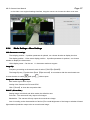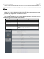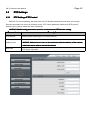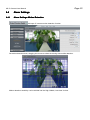
1
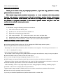
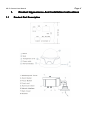
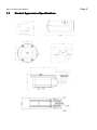
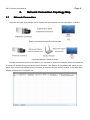
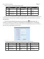
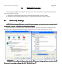
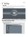
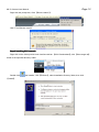
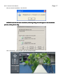
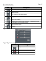
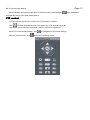
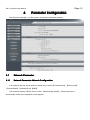
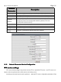
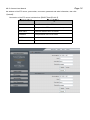
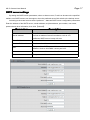
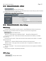
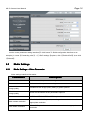
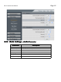
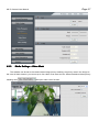
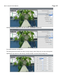
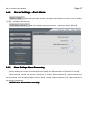
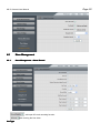
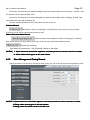
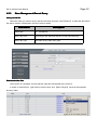
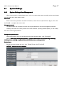
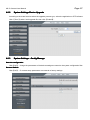
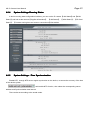
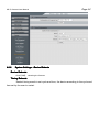
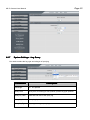
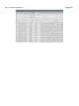
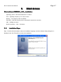
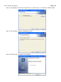
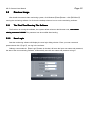
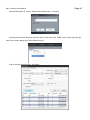
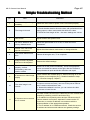
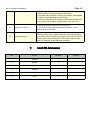
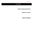
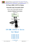
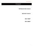
1
HD IP Camera User Manual
HD IP CAMERA USER MANUAL
Version 1.1
Page 2
HD IP Camera User Manual
Directory
1. PRODUCT APPEARANCE AND INSTALLATION INSTRUCTIONS.................. 4
1.1 PRODUCT PART DESCRIPTION................................................................................ 4
1.2 PRODUCT APPEARANCE SPECIFICATIONS.............................................................. 5
2. NETWORK CONNECTION TOPOLOGY MAP ....................................................... 6
2.1 NETWORK CONNECTION.......................................................................................... 6
3. NETWORK ACCESS................................................................................................... 8
3.1 IE SECURITY SETTINGS........................................................................................... 8
3.2 PREVIEW IMAGE....................................................................................................... 9
4. PARAMETER CONFIGURATION........................................................................... 14
4.1 NETWORK PARAMETER.......................................................................................... 14
4.2 MEDIA SETTINGS.................................................................................................... 19
4.3 PTZ SETTINGS...................................................................................................... 24
4.4 ALARM SETTINGS.................................................................................................. 25
4.5 STORE MANAGEMENT........................................................................................... 28
4.6 SYSTEM SETTINGS................................................................................................. 31
5. CLIENT ACCESS...................................................................................................... 37
5.2 PREVIEW IMAGE.................................................................................................... 39
5.3 DEVICE CONFIGURATION PARAMETERS............................................................... 43
6. SIMPLE TROUBLESHOOTING METHOD............................................................48
7. LIST OF ANNEXES.................................................................................................. 49
HD IP Camera User Manual
Page 3
PRONOUNCEMENT
Thank you so much to buy my company
company''s products ,if you have any questions or needs
needs,,
please feel free to contact us
us..
This manual may contain technical inaccuracies
inaccuracies,, or is not consistent with what product
functions and operation
operation,, or printing errors
errors.. We will according to product function enhancement
and update the contents of this manual
manual,, and will be on a regular basis to improve or update
the products or programs described in this manual
manual.. Updated content will join in the new
version of this manual
manual,, without prior notice
notice..
AGREEMENT
In this manual, using the following document conventions:
1)
Click for the mouse the left key click.
2)
Double click to the left mouse button double click.
3)
Right click to the right mouse button click.
4)
With square brackets "【 】" said window name, menu name and data table.
5)
Stressed the need for readers attention with the same number, italic and bold text.
6)
Some pictures for the schematic , please refer to our actual interface software.
PRECAUTIONS FOR SAFE USE
■ Avoid direct glare(If directly at the sun ,will can damage the CMOS image sensor system ).
■ Avoid using the machine in extreme environments.
- Especially in a cold or hot environment. (Such as radiators, heat registers. The working environment is -10
℃ ~ +50 ℃, humidity 90% or less.)
-Avoid close electromagnetic radiation great places.
- Do not install in direct sunlight, strong earthquakes in the region as well as wet, dusty or heavy soot places.
■ Clear the CMOS surface of dust and dirt with a hair dryer.
■ Do not enter through the large voltage(Input supply: DC11V〜15V).
■ CMOS image may appear following specific phenomenon but does not indicate a malfunction.
- White spots: When running more easily seen in the case of a higher temperature environment, or when the
enhanced automatic gain function or use of the cumulative function of the frame.
- Vertical streaking: When a very bright object, such as a strong spotlight or flashlight, streaking may be
generated on the screen or image effects may be distorted.
-Image overlap: Image overlap or flashing may be occur when normal picture, streaks or lines impact.
■ Please do not beat or pressing hard to the product.
If you carry on the above operations may lead to electric shock or cause a fire.
HD IP Camera User Manual
1.
1.1
Page 4
Product Appearance And Installation Instructions
Product Part Description
HD IP Camera User Manual
1.2
Product Appearance Specifications
Page 5
Page 6
HD IP Camera User Manual
2.
2.1
Network Connection Topology Map
Network Connection
There are two main ways between the IP camera and the computer common connection, as shown:
Directly connected through the network cable
Connected through a switch or router
Through the network access to the camera, you first need to obtain its IP address, users can search the
IP camera IP address through the device search software. Click【search】,the software will search out the
name of the current LAN network running cameras, IP address, the port number, number of channels, MAC
address and device ID information, etc.
Page 7
HD IP Camera User Manual
Search tools page mainly includes the following parts:
No.
Description
No.
Description
No.
Description
Device serial
1
ID
4
Device Port
7
2
Device Name
5
Channel
8
Search
3
IP addresses
6
MAC addresses
9
Modify
number
If search out the IP address and the IP address of the computer is not in the same network segment, and
can be modified by the device search software IP cameras IP address, subnet mask and port number and
other parameters.
In the device search software, select the device you want to modify,
is selected state ,click
【Modify】,then enter the new IP addresses, Subnet Mask, Device port and DNS server, click【Modify】,
you can modify the IP addresses of the device. Device search tool currently supports only the IP address of
the search with the same segment of the PC device.
The search tool to modify network parameters page includes the following parts:
No.
Description
No.
Description
No.
Description
1
Device Address
4
Gateway
7
DNS2
2
Device port
5
MAC addresses
8
Modify
3
Subnet Mask
6
DNS1
9
AutoObtain
Page 8
HD IP Camera User Manual
3.
Network Access
The hardware installation is completed, the need for IP camera preview and configuration parameters,
here are two kinds of access:
1. Through the IE browser preview image, configure the parameters of the IP camera;
2. Through the client software preview image , configure the parameters of the IP camera.
3.1
IE Security Settings
NOTICE: When though IE browser preview IP camera image, you need to set the security level of
the browser, in order to facilitate the installation of plug-in.
Open IE browser, to enter the menu→tool/Internet options/ security/ custom level, [ActiveX controls
and plug-ins] are changed to enable in settings, the security level is set to 【security level - low】.
PROMPT: for safety in the preview to the IP camera image, please restore the IE
browser's security settings for the “Default Level
Level””.
HD IP Camera User Manual
3.2
Page 9
Preview Image
Step 1: Log in.
Enter the IP camera IP address in the IE browser address bar, then click enter, or double-click the
network search tool IP addresses. In the login interface, input IP camera user name, password, then click
【Login】, you can enter the main interface to preview.
NOTICE: IP camera factory default IP access to DHCP, if the network without DHCP
server, default fixed IP address is 192.168.1.123, default port is “80
80””.Administrator
user is “admin
admin””, user password is “admin
admin””.
System pop-up prompts to install the ActiveX plugin. As shown, click on the prompt will pop up as shown
in diagram to install ActiveX plug-in dialog.
HD IP Camera User Manual
Page 10
Right-click the prompt bar, Click 【Run the add-in】.
Click 【Yes】Active control.
Step2: Installing OCX controls.
Right-click on the video preview main interface tab bar 【OCX Downloaded】,click 【Save target as】,
saved to the specified directory folder.
Double-click
【Install】.
the installer, click 【Browse】, select installation directory folder, then click
HD IP Camera User Manual
Page 11
After successful installation, click【OK】.
NOTICE: If not the first time installation, following dialog box will appear in the installation
Yes to All
process, click
click【Yes
All】..
Click 【Refresh】 or log in again, you can preview images.
Page 12
HD IP Camera User Manual
Preview interface information:
Icon
Description
Main stream and sub-stream switching
Alarm information
The proportion of video display switching
Snapshot
Start or stop recording
Capture format and stored locally path settings,the default for the system
C:\,according to the actual situation changes
Open or close the listener
Talkback
Image Control:
Image quality parameter setting:
Icon
Description
Brightness, values 0-255 can be set
Contrast,values 0-255 can be set
Saturation,values 0-255 can be set
Default
Page 13
HD IP Camera User Manual
Move the slider can adjust the playback of real-time video parameters(Click
video parameters
automatically return to the initial setting status).
PTZ control:
Through the four direction keys control the PTZ direction of rotation.
Click
PTZ start automatically scan, click again stop PTZ automatically scan.
Click below the function key focal length, aperture and zoom adjustment.
Move PTZ to the desired position, click
Select a preset number, click
can completion of the preset settings.
call the corresponding preset.
Page 14
HD IP Camera User Manual
4.
Parameter Configuration
Click【system settings】, into the system configuration parameter interface.
4.1
Network Parameter
4.1.1
Network Parameter
Parameter--Network Configuration
In accordance with the actual needs of, setting the IP camera【IP addresses】, 【Device port】,
【Subnet Mask】,【Gateway】and【DNS】.
If the network contains a DHCP server, Select 【automatically obtain】, reboot the device to
automatically obtain the IP addresses in the segment.
Page 15
HD IP Camera User Manual
Network
Description
Parameter
IP get way
Manual settings, automatically obtain, dial-up settings is optional
IP address
Setting the IP addresses of the camera
Port
The default port is 80(Recommends that customers not modified)
Gateway
address
4.1.2
Setting the gateway IP addresses of the camera, for example, the device
through the router to access the public network, gateway IP is set to
access public network router IP
Mask address
The default is 255.255.255.0(Recommends that customers not modified)
MAC address
The physical address of the camera
DNS get way
Manual settings, automatically obtain is optional
DNS1
DNS2
Network of preferred and alternate DNS server address
Network Parameter
Parameter--Service Configuration
FTP service settings
FTP server will alarm trigger snap pictures sent by FTP to a specified FTP server,two FTP server can
support, when the preferred server fails switch to the backup server.
According to the actual need to set the preferred ,alternate FTP server configuration parameters. Enter
Page 16
HD IP Camera User Manual
the address of the FTP server, port number, user name, password and other information, then click
【submit】.
Connection of the FTP server is divided into【PORT】and【PASV】.
Parameters
Description
Server address
The IP address of the FTP server
Port
The port of the FTP server , the default port is 21
User name
The user name of the FTP server
Password
The password of the FTP server
PORT
Active connection
PASV
Passive connection
Page 17
HD IP Camera User Manual
SMTP server settings
By setting the SMTP server parameters, when an alarm occurs, E-mail can be sent to the specified
mailbox, two SMTP servers can be support, when the preferred server fails switch to the backup server.
According to the actual need to set the preferred ,alternate SMTP server configuration parameters.
Enter the address of the SMTP server, sender address, recipient address, port number, user name,
password and other information, then click 【submit】.
Parameters
Description
Send EMAIL server address, different mail service provider's
Server address
mail server address format inconsistent, such as 163
mailboxes SMTP server is smtp.163.com
Send EMAIL address
Send mail mailbox
Receive EMAIL address
Receive mail mailbox
Port
The port of the SMTP server, different mail server, port
different. Such as 163 EMAIL server port is 25
User name
The user name of the send mail mailbox
Password
The password of the send mail mailbox
Page 18
HD IP Camera User Manual
→PPPoE
4.1.3 Network Parameter
Parameter→
said open PPPoE function.
Enter PPPoE user name and password, click【submit】,restart, the camera will get a public IP address,
this IP address will be sent to the mailbox settings.
NOTICE: Before using PPPoE, please set E-mail.
→More Settings
4.1.4 Network Parameter
Parameter→
DDNS Settings
If the device using the PPPoE connection network,using DDNS(Dynamic DNS), access device by
domain name, can be an effective solution to the dynamic IP access device brought trouble.
said open DDNS function.
【Server】:Protocol type can be selected as【3322】、【dyndns】and【dnsdynamic】.
If the protocol type is 3322:Please enter the domain name operation server address, for example
wjatest.3322.org.
If the protocol type is dyndns:Please enter the domain name operators server address,for example
members.dyndns.org.
【Update time】:Update the DDNS information according to the set time interval.
【Domain name】:Users apply for their own domain name(The application in DYNDNS or 3322
website domain name).
【Account、Password】:The user name and password of the user account registered in DYNDNS or
3322 website.
After the setup is complete, click [submit] to take effect.
UPNP settings
said open UPNP function.
Page 19
HD IP Camera User Manual
Into the router parameter setting interface(TP-LINK router TL-R406 configuration interface as an
example), in router 【Forwarding rules】 →【 UPnP settings 】options, click 【Enable UPnP】,then click
【Refresh】.
4.2
Media Settings
4.2.1
→Video Parameter
Media Settings
Settings→
Video settings interface information:
Parameters
Description
Parameter 1
Main stream video parameter settings
Parameter 2
Sub-stream video parameter settings
Variable bit-rate streams /
Image quality
Fixed bitrate stream /
Image quality
Frame rate
Main stream resolution
Sub-stream resolution
Variable-bit-rate image quality setting 4 grades optional
Given bit rate stream set six parameters optional
10FPS、15FPS、20FPS、25FPS optional
HD 1080P, HD 720P optional, according to the actual selection of the
appropriate resolution
VGA、CIF optional,to their actual needs to select the appropriate
resolution
Page 20
HD IP Camera User Manual
→Audio Parameter
4.2.2 Media Settings
Settings→
Parameters
Description
Input
Line Input
Volume adjust
Move the slider to adjust the volume slider
Audio channel
Mono
Sampling width
16bits
Sample rate
8K
Compression type
G711
Page 21
HD IP Camera User Manual
4.2.3
→Video Mask
Media Settings
Settings→
The software can be set to the camera video image privacy masking, the privacy area in the image on
the cover in black-rimmed, you can set up to four video cover area at most. Select the desired video privacy
masking area,
said open video cover function.
Page 22
HD IP Camera User Manual
In the video cover regional settings interface, drag the mouse can choose the video cover area.
4.2.4
→More Settings
Media Settings
Settings→
OSD Parameters settings
Time display position:9 position parameter is optional, can choose whether to display the time.
Text display position:Video name display position,9 position parameter is optional , can choose
whether to display the video name.
Video display name:Can be set,11 characters maximum support.
Image flip
Frequency according to the actual needs of select 【50HZ】or【60HZ】.
The image flip way 【upside down】and 【Flips around】 in accordance with the actual needs can
choose whether to enable,
said open,
said not open.
Composite video configuration
BNC mode signal video output.
Analog video formats into PAL and NTSC.
Click 【Close】 to close the composite video.
IR cut filter
IR-CUT
IR-CUT(IR
filter)
Setting image color black and white mode, the default is auto.
Full color:The camera will only output color images.
Blackwhite:The camera will only output the monochrome image.
Auto: According to the characteristics of device (The overall brightness of the image or whether infrared
lights attached) selection output color or monochrome image.
Page 23
HD IP Camera User Manual
Timing:For the user to set to force the image color or monochrome time, sunrise elected: 06:00:00, the
Sunset time to 18:00:00, in this time period image are color, the rest of the period of time for the monochrome
image.
Iris control
The iris control mode is divided into manual and automatic optional.
Auto iris mode for devices connected to the auto iris lens. When the light changes, auto iris will change.
Manual iris mode, iris at maximum. The default for the auto iris.
Real-time streaming media
When you enable RTSP function, users can support standard RTSP protocol ( for example: player VLC )
to real-time preview of the camera, audio and video streaming.
Parameters
Description
RTSP Stream 1
The main data rate preview video
RTSP Stream 2
The Sub data rate preview video
RTSP Video Stream1
Without audio the main data rate preview video
RTSP Video Stream2
Without audio the sub data rate preview video
RTSP Audio Stream1
Alone audio function, without preview video
Password authentication
said open,
said not open
Page 24
HD IP Camera User Manual
4.3
PTZ Settings
4.3.1
PTZ Settings
Settings--PTZ Control
Before PTZ control operating, first make sure the PTZ decoder parameters have been set correctly.
Decoder parameters can be set by software device. PTZ control parameter interface set PTZ protocol,
address code, protocol speed and other parameters.
NOTICE: RS-485 setting parameters must be consistent and PTZ decoder setting.
Parameters
PTZ protocol
Description
Matching with the dial type PTZ control protocol
Setting address of the ball machine, the default is 1
Address code
NOTICE: Address here is sure to be consistent with the address of the camera,
otherwise not be able to control the camera
Baud rate
PTZ speed adjustable
Page 25
HD IP Camera User Manual
4.4
Alarm Settings
4.4.1
Alarm Settings
Settings--Motion Detection
said open IP camera motion detection function.
Set motion detection area, dragging the mouse to select the arming area mobile detection.
Motion detection sensitivity can be divided into the High, Middle, Low three choices.
HD IP Camera User Manual
Page 26
Setting the alarm output port: You can choose 【Disable】or【Port1】.
Set mobile detection arming time.
The arming time can choose one day in seven days a week. Daily only can set a time period.
Optional all-day armed or sub-arming, click【Cancel】to cancel a day arming time.
Page 27
HD IP Camera User Manual
4.4.2
→Port Alarm
Alarm Settings
Settings→
said open port alarm function, the alarm interval time can select, such as setting
【15s】, said alarm intervals 15s,
said open linkage output port function,output port select 【Port1】.
4.4.3
Alarm Settings
Settings--Alarm Processing
Alarm handling can choose to enable【Save SD card】and【Send mail】and【Send FTP server】.
Alarm captured number can choose 1-5 pictures, or choose 【Don’t snapshot】, capture interval time
can be selected, such as setting capture interval 【5s】, setting capture snapshot【3】, said at intervals of
5S capture 3 snapshots.
NOTICE: Save SD card alarm recording.
HD IP Camera User Manual
4.5
Store Management
4.5.1
→Alarm Record
Store Management
Management→
said open SD card recording function.
said covering the first video.
Cut Type
Page 28
Page 29
HD IP Camera User Manual
Cut by time: Set each piece of video packaged long when record enable. Such as setting 【1min】, said
one minute of each video package a file.
Cut by size: Set each piece of video packaged size when record enable. Such as setting 【5M】, said
video size each reach 5M package a file.
Cut size: Actual parameters of the cutting time and size of the cut.
IO Alarm Record
said start IO alarm recording type, recording time can be set up one day a week,
every day can be set up to three time periods at most.
Motion Detection Alarm Record
said to start the motion detection alarm recording type, recording
time can be set up one day a week, every day can be set up to three time periods at most.
said full day recording.
After setting the parameters,click【Submit】settings to take effect.
1. If you choose to record time segment, each time period can not be crossed or contain.
NOTICE
NOTICE:1.
2. Alarm video stream types in the main stream.
4.5.2
Store Management
Management--Timing Record
Timing record time can be set up one day a week, every day can be set up to three time periods at most.
If you choose to record time segment, each time period can not be crossed or contain.
NOTICE: 1.
1.If
Timing video stream types in the sub-stream.
2.
2.Timing
Timing video file will be saved on the SD card.
3.
3.Timing
Page 30
HD IP Camera User Manual
4.5.3
Store Management
Management--Record Query
Query record file
Select the video you need to query start and end time and type, click【Submit】, if video files that match
the search criteria, is displayed in the list of search results.
Parameters
Description
Item/Page
15、25 optional
Query By Time
According to the start and end time of SD video file query
Query By Type
SD video file by video query type
Download video files
Video search is completed, choose relevant video file downloaded to the local PC.
In search of video file list, right-click on the file name, click 【Save Target】, saved to the specified
directory folder.
HD IP Camera User Manual
4.6
System Settings
4.6.1
System Settings
Settings--User Management
Page 31
When current user is an administrator user, users can create other users according to the actual needs,
you can create up to nine users at most.
Add Users
Enter a user name, password and other information, select the user 【Permissions 】type, then click
the 【Add】 to complete the user to add.
Change password
The administrator can modify the current user's login password in the user management interface.
Ordinary user clicks on a video preview of the main interface 【modify password】tab, you can modify
the current user's login password.
Change user permissions
Select a permission types in a list user need to modify the drop-down, click 【Change】.
Notice: admin only modify the password, system administrator has all operating authority,
ordinary users authority to operate the main interface has a video preview.
Delete Users
Behind the need to delete the user, click 【Delete】,then click 【Confirm】.
Admin can not be deleted.
NOTICE
NOTICE:Admin
HD IP Camera User Manual
4.6.2
Page 32
System Settings
Settings--Device Upgrade
According to the actual need to select the upgrade process type, select the application or PTZ software.
Click 【Scan】,select local upgrade file, then click 【Submit】.
4.6.3
→Config Manage
System Settings
Settings→
Save the configuration
Click【OK】,change the parameters of the device settings are saved to the system configuration files.
Recover Default
Click【OK】,IP camera setup parameters are restored to factory settings.
Page 33
HD IP Camera User Manual
4.6.4
System Settings
Settings--Running Status
In device running state configuration interface, you can set the IP camera【LAN Status】and【WAN
Status】,and look at the camera【Supplier Information】、【LAN Status】、【WAN Status】、【SD Card
Status】、【Camera running time and users to connections】informations.
4.6.5
→Time Synchronization
System Settings
Settings→
Enable NTP, through NTP server regular synchronize on the device, to ensure the accuracy of the time
of the device system.
said enable NTP function, then select the corresponding server
address and Synchronization time interval.
Time can be set according to the actual needs.
HD IP Camera User Manual
4.6.6
Page 34
System Settings
→Device Reboots
Settings→
Device Reboots
Click【OK】,rebooting the Camera.
Timing Reboots
Restart timing needs to set cycle and time, the device according to the cycle and
time set by the user to restart.
Page 35
HD IP Camera User Manual
4.6.7
→Log Query
System Settings
Settings→
You need to select the log type and subtype of querying.
Parameters
Description
Item/Page
15、25 optional
Query Rule
Query time, according to user queries, queries by type optional
Query By Time
Start and end time of the query log
Query By User
Query log by user name
Query By Type
Sys, app, user type query log
HD IP Camera User Manual
Page 36
Page 37
HD IP Camera User Manual
5.
Client Access
V1.2
installation.
Client software ICMS9000
ICMS9000(V1.2
V1.2)installation.
Operating system:Microsoft Windows XP or above.
CPU:Operating frequency of 1.5 Ghz or more.
Memory:The capacity of 2G over DDR2.
Hard disk:Hard disk capacity as the video data is required to save time.
LAN:100Mbps or above.
Monitor resolution:1024 × 768 above.
5.1.1
Installation Steps
Step 1: Double-click the installer, select the installation language, and then software Setup dialog box is
displayed, then click 【Next】 to continue the installation.
HD IP Camera User Manual
Page 38
Step 2: Click【Next】to install to the default folder, or click【Change…】to install to a different folder.
Step 3: Click 【install】, begin the installation process.
Step4: Click【Finish】, to complete the installation.
HD IP Camera User Manual
5.2
Page 39
Preview Image
After install the network video monitoring system, click Windows【Start】button→click【SSClient】
running the monitoring software. Or click on the desktop shortcut icon to run the monitoring software.
5.2.1
The First Time Running The Software
The first time to running the software, the system default exists an administrator user, user name:
admin, password: 123456. The password can be modified after landing.
5.2.2
User Login
Start the monitoring software will display the user login dialog window. Enter your user name and
password and click 【Login】, can log in the software.
Ordinary users make the 【Auto Login】status is checked, will save the input user name and password,
the start of the next monitoring software, automatically save the user name and password to log in.
HD IP Camera User Manual
5.2.3
Page 40
Add Device
Click on the tab bar 【Configuration】tab, enter the device management interface. Right-click on a list of
tree any blanks, will pop up 【Add Region】menu,as shown:
HD IP Camera User Manual
Page 41
Select【Add Region】, pop up 【Add Region】dialog box,as shown:
According to the actual demand, enter the name of the zone, click 【OK】, then mouse right-click the
name of the newly added area, select【Add Device】.
Pop up Add Device dialog box,as shown:
HD IP Camera User Manual
Page 42
In the Add Device dialog box, click 【Scan Device】,you can search the current running in the LAN IP
address of the network camera, double-click the device list, input 【user name】、【password】and other
information, then click【OK】, Complete device add.
Add a device manually, 【Device Name】 needs to fill, device type select【IP Camera】, 【Register
Mode】 select 【Ordinary IP】, 【Port number】 the default is 80, input devices【IP】addresses、【user
name】、【password】、【DNS】and other information, then click【OK】, Complete device add, as shown:
Click 【Preview】 tab, enter the preview screen, as shown. Double click on the list of the camera
channel node, to preview the pictures.
HD IP Camera User Manual
Page 43
More detailed parameter configuration,please refer to the corresponding section of the 【network video
monitoring client ICMS9000 (V1.0) User's Guide】. The documentation of the use of the computer operating
system【Start】→【Program】→【Network Video Monitoring Program】.
5.3
Device Configuration Parameters
In order to meet the needs of different environments in reality, Through the network video monitoring
system parameters of the camera can be configured, the specific operation is as follows:
Click 【The Tab Bar 】configuration tab, right-click the device node, Select 【Device Setting】, enter
【IPC Parameter Configuration】interface.
HD IP Camera User Manual
5.3.1
Page 44
Device Information
In the interface of device basic information, you can view the camera【Internal Coding】、【Device
Registration Code】、【Factory Model】、【Factory coding】and other information.
5.3.2
Network Parameters
In accordance with the actual needs, setting up a IP camera【IP addresses】、【Mask address】、
【Gateway address】and【DNS】.
If your network contains a DHCP server, select【The Dynamic DHCP Assigned IP】, reboot the device
to automatically obtain the IP address in the segment.
Page 45
HD IP Camera User Manual
5.3.3
Video Parameters
Video parameters set interface information:
Parameters
Description
Frame Rate
10FPS、15FPS、20FPS、25FPS optional
Stream / Quality Control
Constant bit rate, variable bit-rate optional
Mode
Fixed Bit Rate Stream /
Fixed rate stream setting 5 parameters optional
Quality Level
Variable Bit Rate Stream /
Four levels of the variable bit-rate image quality
Quality Grade
optional
Page 46
HD IP Camera User Manual
5.3.4
Video Parameters
ParametersⅡ
Mobile slider can adjust the channel playing video parameters(Click【Restore Defaults】video
parameters automatically return to the initial setting status).
5.3.5
Audio Parameters
Parameters
Description
Input Mode
Line input
Audio channels
Mono
Audio Sample Width
16bits
The Audio Sampling Frequency
8K
The Type Of Audio Compression
G711
Page 47
HD IP Camera User Manual
5.3.6
PTZ Parameters
Before PTZ control Operating, first make sure the PTZ decoder parameters have been set correctly.
device decoder parameters can be set by software remote .
In the PTZ control parameter interface set PTZ address, PTZ script file, PTZ control speed and other
parameters.
Notice: RS-485 PTZ decoder setting parameters must be consistent with PTZ decoder setting.
Parameters
PTZ Script
Agreement
Description
Matching with the dial type of PTZ control protocol
Set to the corresponding dome address, default is 1
PTZ Address
The address must be consistent with the
NOTICE
NOTICE:The
camera., otherwise not be able to control the camera
PTZ Control
Speed
PTZ speed adjustable
Page 48
HD IP Camera User Manual
6.
Simple Troubleshooting Method
No.
Fault
1
Screen no image or image
instability
Check the video cable or power cord is connected properly.
2
The image is blurred
1. Check whether there is dirt on the lens, with professional lens
wiping paper or clean cotton swab with alcohol to clean.
2. Check the focal length is fine,the menu settings are correct.
3
Dim Picture
Adjust monitor and aperture CNT.
4
No motion detection and
privacy shaded boxes
Check the option button is on or off, or check the menu
parameters.
5
Screen color cast in the
special environment
Adjust the white balance mode menu or change direction.
6
The screen flashes more
than
Camera is facing the sun, TV or computer.
7
Image functions impaired
and can not be adjusted
Restore the default settings
8
Camera is not working
properly, surface
overheating, and even
smell or smoke
Please cut off the power immediately, check the appropriate
power connected the camera to the right, after the camera to
take professional repair technician detection and repair.
9
IE browser no video image
display
Check whether the installed plug-in. When first using IE to visit
IP Camera, must install the plug. ( Detailed installation steps
【3.2 Preview Image】 Chapter.)
10
The video image is not
smooth
11
IE browser can not access
the IP camera
Resolvent
1. The video frame rate parameter tuning IP camera high.
2. Users to connect too many, can turn off the part of client or
set IP camera reduced frame rate.
3. Network broadband is too low, you can reduce the video
frame rate or lower bit rate.
1. Network blocked. PC access network to test network access
can work normal, the first rule of cable fault, the PC network fault
caused by poisoning, until PC each other Ping.
2. IP address is occupied by other devices. Disconnect the IP
Camera network connection, separate IP camera and a PC
connection, to set the IP address in accordance with the
recommendation of the appropriate operation.
3. The IP address is on a different network. Check the server's
IP address and subnet mask address and gateway settings.
Page 49
HD IP Camera User Manual
4. There are conflicts within the network physical address and IP
Camera. Modify the physical address IP Camera.
5. The Web port is modified. Contact your network administrator
to obtain the corresponding port information.
6. Unknown. Restore the IP camera to the factory defaults, then
reconnect the system again, default fixed IP 192.168.1.123.
12
13
Intercom no sound
1. Check the audio connections for audio input.
2. Check the IP Camera audio parameter settings, to see
whether to open the audio.
Audio ineffective
When there is a lot of audio sounds murmur, very serious
distortion phenomenon, please check the input signal level line
input. Most of the time when input signal is not a line input(Such
as with zoom active microphone), do not match with the input
level of IP Camera, image saturation distortion.
7.
List Of Annexes
No.
Name
Quantity
1
Camera
1
2
Manual
1
3
Drier
1
4
Screws
1
5
Certificate
1
6
CD
1
Remark