1
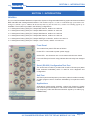
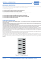
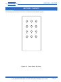
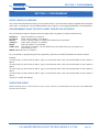
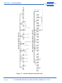
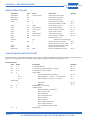
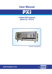
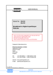
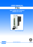
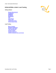
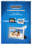
pickering
USER MANUAL
SYSTEM 10
4 X CHANGEOVER RELAY SPDT RF RELAY MODULE
(MODEL No. 10-710A )
www.pickeringtest.com
pickering
ISO 9002
Reg No. FM38792
Pickering Interfaces Ltd.
Stephenson Road
Clacton-on-Sea
CO15 4NL
United Kingdom
Pickering Interfaces Inc.
966 SW 6th Street
Grants Pass
Oregon 97526
USA
Pickering Interfaces GmbH
Buchenstrasse 15
D-77880
Sasbach
Germany
Pickering Interfaces AB
Karl Nordströmsväg 31
432 53
Varberg
Sweden
Tel:
Fax:
+44 (0)1255-428141
+44 (0)1255-475058
Tel:
Fax:
541 471 0700
541 471 8828
Tel:
Fax:
+49 7841 66 49 10
+49 7841 66 49 12
Tel:
Fax:
+46 340-69 06 69
+46 340-69 06 68
E-Mail:
[email protected] E-Mail:
[email protected]
E-Mail:
[email protected]
E-Mail:
[email protected]
4 X CHANGEOVER RELAY SPDT RF RELAY MODULE 10-710A
Page 1
pickering
© COPYRIGHT (2002) PICKERING INTERFACES. ALL RIGHTS RESERVED.
No part of this publication may be reproduced, transmitted, transcribed, translated or stored in any form, or by
any means without the written permission of Pickering Interfaces.
Technical details contained within this publication are subject to change without notice.
Page ii
4 X CHANGEOVER RELAY SPDT RF RELAY MODULE 10-710A
pickering
TECHNICAL SUPPORT
For Technical Support please contact Pickering Interfaces either by phone, fax, the website or via e-mail.
WARRANTY
All products manufactured by Pickering Interfaces are warranted against defective materials and workmanship for
a period of two years from the date of delivery to the original purchaser. Any product found to be defective within
this period will, at the discretion of Pickering Interfaces be repaired or replaced.
Warranty is on a return to factory basis, however, for most systems, the module may be replaced on a module
exchange basis. A module will be delivered to the user and the faulty part returned to Pickering Interfaces on
receipt.
Products serviced and repaired outside of the warranty period are warranted for ninety days.
Extended warranty and service are available. Please contact Pickering Interfaces by phone, fax, the website or via
e-mail.
ENVIRONMENTAL POLICY
Pickering Interfaces operates under an environmental management system similar to ISO 14001.
Pickering Interfaces strives to fulfil all relevant environmental laws and regulations and reduce wastes and releases
to the environment. Pickering Interfaces aims to design and operate products in a way that protects the environment
and the health and safety of its employees, customers and the public. Pickering Interfaces endeavours to develop
and manufacture products that can be produced, distributed, used and recycled, or disposed of, in a safe and
environmentally friendly manner.
Worldwide Technical Support and Product Information
http://www.pickeringtest.com
Pickering Interfaces Headquarters
Stephenson Road Clacton-on-Sea CO15 4NL United Kingdom
Tel: +44 (0)1255-428141
Fax: +44 (0)1255-475058
E-Mail: [email protected]
Worldwide Offices
Germany Tel: +49 7841 66 49 10
Fax: +49 7841 66 49 12
E-Mail: [email protected]
Sweden
Tel: +46 340-69 06 69
Fax: +46 340-69 06 68
E-Mail: [email protected]
USA
Tel: (541) 471 0700
Fax: (541) 471 8828
E-Mail: [email protected]
4 X CHANGEOVER RELAY SPDT RF RELAY MODULE 10-710A
Page iii
pickering
THIS PAGE INTENTIONALLY BLANK
Page iv
4 X CHANGEOVER RELAY SPDT RF RELAY MODULE 10-710A
pickering
CONTENTS
Copyright Statement .......................................................... ii
Technical Support and Warranty....................................... iii
Contents (this page)........................................................... v
Section 1
Introduction......................................................................... 1.1
Section 2
Connector Pin Outs............................................................ 2.1
Section 3
Programming ...................................................................... 4.1
Section 4
Reconfiguration .................................................................. 5.1
Section 5
Technical Specification...................................................... 6.1
4 X CHANGEOVER RELAY SPDT RF RELAY MODULE 10-710A
Page v
pickering
THIS PAGE INTENTIONALLY BLANK
Page vi
4 X CHANGEOVER RELAY SPDT RF RELAY MODULE 10-710A
SECTION 1 - INTRODUCTION
pickering
SECTION 1 - INTRODUCTION
GENERAL
The 10-710A Power Matrix Module forms part of the System 10 Programmable Switching system and uses a standard
IEEE-488.2/RS-232 message based interface. The module comprise a bank of 4 individual high performance R.F.
changeover switches (50 or 75Ohm, Bi directional) with very low insertion loss, suitable for handling signals up to
3000MHz. The module is provided in the following configurations:
•
•
•
•
•
•
4 x Changeover Relay (SPDT) R.F. Relays BNC Version, 50Ohm 10-710A-504
4 x Changeover Relay (SPDT) R.F. Relays SMB Version, 50Ohm 10-710A-514
4 x Changeover Relay (SPDT) R.F. Relays SMA Version, 50Ohm 10-710A-524
4 x Changeover Relay (SPDT) R.F. Relays BNC Version, 75Ohm 10-710A-704
4 x Changeover Relay (SPDT) R.F. Relays SMZ/Type 43 Version, 75Ohm 10-710A-714
4 x Changeover Relay (SPDT) R.F. Relays 1.0/2.3 Version, 75Ohm 10-710A-744
Front Panel
The module front panel LEDs are as follows:
Power LED - Connected to power system supply.
Active LED.- On whenever one or more matrix switches are closed.
Four red LEDs (one for each relay) indicate when the relay has changed
over
Serial (RS-232) Configuration/Test Port
The 20-947-001 module is provided with a built-in RS-232 port (9600
baud software handshake) which is used for error diagnosis and
configuration.
Self-Test
Self-Test is performed at power up and at any other time either manually
or under program control. Faults are indicated by front panel mounted
LEDs.
Applications
Applications include aerial switching, routing high frequency signals
into oscilloscopes and analysers. The 75Ohm versions are suitable for
high frequency video and telecommunication signals up to 3GHz (e.g.
622MBit data).
4 X CHANGEOVER RELAY SPDT RF RELAY MODULE 10-710A
Page 1.1
SECTION 1 - INTRODUCTION
pickering
MECHANICAL DESCRIPTION
The 10-710A module conforms to the 3U height Eurocard standard and comprises a PCB housed in a 160mm deep
screened plug-in module. Panel width is 60.96mm. The module comprises:
•
•
•
•
•
•
•
•
SIMM Control Daughtercard
Four RF Changeover relays mounted on a Relay daughtercard
One motherboard mounted 64-way DIN 4162 connector
Twelve Front Panel mounted connectors BNC, SMB, SMA, SMZ/Type 43 or 1.0/2.3
Four Front Panel mounted red relay status LEDs
One Front Panel mounted red POWER LED mounted on a Status PCB
One Front Panel mounted green ACT(active) LED mounted on a Status PCB
One Front Panel mounted RS232 connector
FUNCTIONAL DESCRIPTION
The 10-710A 4 x Changeover Relay Module (Figure 1.2), is powered by +5V and +12V supplies from the variable
input power supply.
The module comprises a Mothercard which provides mounting for a plug-in Microprocessor Control SIM daughtercard
(Slot 1) and a plug-in Relay daughtercard (Slot 2).
The module interface to the device under test is via four sets of front panel mounted coaxial connectors. Each set
comprises Normally Open, Normally Closed and Common connectors for each of the four changeover relays.
The Microprocessor Control SIM daughtercard accepts control signals from the backplane connector J1. These
signals are processed by microprocessor U1 and distributed to the 4 x Changeover Relay daughtercard (Figure 1.2)
which is connected at Slot 2. The control signals are passed via a bus to Relay Driver U2 which in turn provides
drive signals for the relays.
Driver U1 mounted on the mothercard provides drive for the four front panel mounted LEDs. These LEDs illuminate
when the associated relays change from Normally Closed to Normally Open.
The Module also has a built in RS-232 port (9600 baud, XON/XOFF, 8 bit, no parity). This is provided on a 4 pin
Molex datamate connector on the front panel. A separate adapter lead to allow use with a standard 9 pin D-type
is available. The RS-232 port allows the module to be configured, controlled and monitored from any RS-232
terminal.
Normally open
Common
Normally closed
Normally open
Common
Normally closed
Normally open
Common
Normally closed
Normally open
Common
Normally closed
Figure 1.1 - Relay Schematic
Page 1.2
4 X CHANGEOVER RELAY SPDT RF RELAY MODULE 10-710A
SECTION 1 - INTRODUCTION
pickering
MOTHERBOARD
STATUS PCB
POW
ACT
CONFIG
Slot 2
Normally open
J2
Common
J1
DIGITAL
BUS
Slot 1
SIM
MODULE
FRONT PANEL
RELAY PCB
CONTROL
BUS
Common
C
Normally closed
NC
Normally open
NO
C
Normally closed
NC
Normally open
NO
U2
Common
+12V
+5V
0V
Common
NO
C
Normally closed
NC
Normally open
NO
C
Normally closed
NC
1
LED DRIVE
2
U1
3
4
Figure 1.2 - 4 x Changeover Relay Module (10-710A): Functional Block Diagram
4 X CHANGEOVER RELAY SPDT RF RELAY MODULE 10-710A
Page 1.3
SECTION 1 - INTRODUCTION
pickering
THIS PAGE INTENTIONALLY BLANK
Page 1.4
4 X CHANGEOVER RELAY SPDT RF RELAY MODULE 10-710A
SECTION 2 - PIN OUTS
pickering
SECTION 2 - PIN OUTS
The following pages provide pin outs for the 4 x Changeover Relay Module 10-710A.
NO
C
NC
NO
C
NC
NO
C
NC
NO
C
NC
Figure 2.1 - Front Panel: Pin Outs
4 X CHANGEOVER RELAY SPDT RF RELAY MODULE 10-710A
Page 2.1
SECTION 2 - PIN OUTS
pickering
A
GND
5V (RELAY)
5V (LOGIC)
DIO1
DIO3
EOI
NRFD
IFC
ATN
DIO5
DIO7 (MOSI)
REN
Settled
Reserved
ANALOG 1.1
ANALOG 1.2
ANALOG 1.3
ANALOG 1.4
ANALOG 1.5
ANALOG 1.6
ANALOG 1.7
ANALOG 1.8
ANALOG 1.9
ANALOG 1.10
SLOT ADDRESS BIT 0
SLOT ADDRESS BIT 2
BACKPLANE ADDRESS BIT 4
BACKPLANE ADDRESS BIT 1
Not Connected
12V (RELAY)
5V (LOGIC)
GND
C
1
2
3
4
5
6
7
8
9
10
11
12
13
14
15
16
17
18
19
20
21
22
23
24
25
26
27
28
29
30
31
32
GND
12V (RELAY)
POWER SUPPLIES
5V (LOGIC)
DIO2
DIO4
DAV
NDAC
SRQ
SYSTEM DIGITAL BUS
Reserved
(Parallel and Serial Bus)
DIO6 (MISO)
DIO8 (SCK)
Not Connected
Reserved (-SS)
Not Connected
ANALOG 1.1
ANALOG 1.2
ANALOG 1.3
ANALOG 1.4
ANALOG 1.5
ANALOG BUS
ANALOG 1.6
ANALOG 1.7
ANALOG 1.8
ANALOG 1.9
ANALOG 1.10
SLOT ADDRESS BIT 1
POSITION
SLOT ADDRESS BIT 3
LOCATOR
BACKPLANE ADDRESS BIT 0
BACKPLANE ADDRESS BIT 2
Not Connected
12V (RELAY)
5V (LOGIC)
POWER SUPPLIES
GND
NOTE:
The analog bus is not used.
Figure 2.2 - System 10 Backplane Connector: Pin Outs
Page 2.2
4 X CHANGEOVER RELAY SPDT RF RELAY MODULE 10-710A
SECTION 3 - PROGRAMMING
pickering
SECTION 3 - PROGRAMMING
SELECT MODULE ADDRESS
The module internal address is factory pre-set, please refer to case schematic diagram supplied with the System
10/20 case. To change the internal address please refer to Section 4, Reconfiguring Modules to Your Application.
PROGRAMMING USING THE INTELLIGENT GPIB/RS-232 INTERFACE
The R.F. Module is simple to program either by single relay or by pattern (4 relays simultaneously)
ARESET a
CLOSE a,b
DELAY t
OPEN a,b
RESET
VIEW? a[,b]
Open all switches on module a
Close switch number b on module a
Force a minimum delay of t milliseconds between two instructions
Open switch number b on module a
Open all switches on all modules
View status of module a, can be viewed at any time either as a byte orby switch as a
logical value (1 or 0)
WRITE a,w Send byte w to module a
For more details on programming see the programming manual for the IEEE-488.2/RS-232 interface module.
Example
To switch relay 1 of the module in addr 5, type cl 5,1 and press return. LED 1 should illuminate on the module in
addr 5
To switch relay 2 of the module in addr 5, type cl 5,2 and press return. LED 2 should illuminate on the module in
addr 5
To switch relay 3 of the module in addr 5, type cl 5,3 and press return. LED 3 should illuminate on the module in
addr 5
To switch relay 4 of the module in addr 5, type cl 5,4 and press return. LED 4 should illuminate on the module in
addr 5
Type VI? to confirm the settings.
OPERATING SPEED
Module operating speed, i.e. the time taken to open or close a channel, is approximately 10ms using the 10-921 IEEE-488.2/
RS-232 interface module.
4 X CHANGEOVER RELAY SPDT RF RELAY MODULE 10-710A
Page 3.1
Page 3.2
*CLS
w
a
b
a
b
m
m
*SRE *SRE? *STB?
Status Reporting
a
OPEN
CLOSE
WRITE
Switch/Digital Output
*ESE *ESE? *ESR?
a
RESET ARESET
Clear
c
c
b
e
a
a
a
CHAN
Multiplexer
y
x
a
MCLOSE
y
*IDN?
*RST
*TST?
Internal Operations
*RCL
*SAV
Stored Settings
*OPC *OPC?
*WAI
Synchronisation
b
a
*DMC
t
a
x
DELAY
Time
MOPEN
Matrix
IEEE-488.2 STANDARD INSTRUCTION SET
a
READ?
Digital Input
SWITCHING INSTRUCTION SET
m
m
Future Enhancements
*LRN?
Learn
REPORT? ERRNO? DIAGNOSTIC?
Errors
*GMC? *LMC? *PMC
Macros
a
TYPE?
*EMC *EMC
a
VIEW?
Status
SECTION 3 - PROGRAMMING
pickering
Figure 3.1 - Interface Module Instruction Set
4 X CHANGEOVER RELAY SPDT RF RELAY MODULE 10-710A
SECTION 4 - RECONFIGURATION
pickering
SECTION 4 - RECONFIGURING MODULES
MODULE CONFIGURATION
Modules are configured using the internal RS232 Serial port connected via the 4 pin Datamate connector on the
front panel with the supplied lead. Configuration data is stored within the module in EEPROM and may be altered
using a dedicated terminal or a computer terminal program, set up as follows:
Baud rate
9600
8 Data bits
1 Stop bit
No parity.
There are three groups of commands available via the internal RS232 interface which are used to operate and configure the module. The groups are;
1.
User Instruction Set: Commands to operate switches, provide relay status and module information.
2.
Configuration Instruction Set: Commands to set up the module to a specific configuration.
3.
Factory Instruction Set: Commands to set the module self test limits.
All instructions must be entered as shown for the command to operate correctly.
The module is configured with the following factory settings
Software V2.01, 23-04-98
(c) Pickering Interfaces 1997
cf
Configured as 4 x RF Changeover Relays
CF 1 5
Address 19
CF 2 0
MUX Banks
CF 3 0
Pod
CF 4 0
Switch mode
CF 5 0
Ruthenium Switch
CF 6 0
Panel Width
CF 7 86
Self test
CF 8 4
Module data 1, Bits Out
CF 9 0
Module data 2, Bits Out Start
CF 10 0
Module data 3, Bits In
CF 11 0
Module data 4, Not used
CF 12 0
Configuration Mode
zl
ZL 1 30
Min coil 200R
ZL 2 144 Max coil 5900R
ZL 3 69
Contact On 1380mR
ZL 4 48
Contact Change 960mR
ZL 5 128 Contact Off
ZL 6 136 Service Temp. 54 C
ZL 7 168 Fail Temp. 66 C
ZL 8 244 Min Logic 4.7V
ZL 9 100 Min LED 1.9V
ZL 10 180 Max LED 3.5V
ZL 11 128 Min Panel LED 2.5V ZL 12 176 Max Panel LED 3.4V
ZL 13 180 Min Relay 9.0V (10.9V) ZL 14 254 Max Relay 12.7V
ZL 15 10
Fail Retry
ZL 16 25
Settle Delay 250us
4 X CHANGEOVER RELAY SPDT RF RELAY MODULE 10-710A
Page 4.1
SECTION 4 - RECONFIGURATION
pickering
USER INSTRUCTION SET
Command
Ascii
Bytes
Description
Relay Block
BL
8 bytes of data
64 bit block of relay data.
Block View?
BV
Diagnostic?
DI
Dump
DU
Close
CL
Close
Example
View status of all relays.
Report self test errors.
0
Relay test history dump.
DU 0
1
Dump even if data is invalid.
DU 1
relay
Close a relay contact.
CL 7.
CL
bank,channel
Close a MUX channel.
CL 1 4.
Close
CL
x axis, y axis
Close a matrix crosspoint.
CL 7 3.
Open
OP
relay
Open a relay contact.
OP 7.
Open
OP
bank,channel
Open a MUX channel.
OP 1 4.
Open
OP
x axis, y axis
Open a matrix crosspoint.
OP 7 3.
Reset
RS
Service?
Reset all relays to off.
SR
Test
TS
Type?
TY
Who?
WH
MUX Clear
XC
Report all service warnings.
0
Return result of last self test.
TS 0
1
Initiate self test and return result.
TS 1
Returns module type data string.
Module introduction string.
bank
Reset an individual mux bank.
XC 01.
CONFIGURATION INSTRUCTION SET
The Configuration instruction allows a module to be set up for a specific application by setting up its address, bank and self test
options etc.. To view the current configuration settings without altering any parameters simply type "CF".
Config Command
Ascii
Bytes
Description
Example
CF
1 x
x = Module address.
CF 1 5
CF
2 x
x = Number of multiplexer banks in module.
CF 2 4
CF
3 x
x = Number of pods in module.
CF 3 0
CF
4
Switch Mode
0
For I/O Modules mode is always 0.
CF 4 0
0 or 1
MUX modules, 0 = normal, 1 = multi channel
CF 4
Matrix modules, 0 = RF, 0 or 1 for others.
CF 5
Ruthenium.
CF 5 0
Mercury.
CF 5 1
0 or 1
Switch Type.
0
1
CF
6
Panel Width. For future use.
CF
7
Selftest Options
Each bit enables a specific test.
Bit 0 = Spare. LSB.
Bit 1 = RAM test.
Bit 2 = Panel LED test.
Bit 3 = Coil test.
Bit 4 = LED test.
Bit 5 = Switch Contact test.
Bit 6 = Temperature test.
Bit 7 = Selftest at start up. MSB
CF
Page 4.2
8
Module data 1
4 X CHANGEOVER RELAY SPDT RF RELAY MODULE 10-710A
SECTION 4 - RECONFIGURATION
pickering
CF
9
Module data 2
CF
10
Module data 3
CF
11
Module data 4
CF
12
Configuration mode
Module data is dependent upon Module type as follows;
Module data byte
I/O Module
MUX Module
Matrix Module
1
Bits Out
Size
X Size
2
Bits out start
Start
Y Size
3
Bits in
Not used
X Start
4
Not used
Not used
Y Start
4 X CHANGEOVER RELAY SPDT RF RELAY MODULE 10-710A
Page 4.3
SECTION 4 - RECONFIGURATION
pickering
THIS PAGE INTENTIONALLY BLANK
Page 4.4
4 X CHANGEOVER RELAY SPDT RF RELAY MODULE 10-710A
SECTION 5 - SPECIFICATION
pickering
SECTION 5 - SPECIFICATION
GENERAL SPECIFICATION (ALL VERSIONS)
Maximum Voltage
50V d.c.
Maximum Power
10W
Maximum Carry Power (900MHz)
15W
Maximum Switch Current
0.1A
On Path Resistance
< 200 mOhm
Off Path Resistance
> 108Ohm
Differential Thermal Offset
< 20µV
Expected Life (Low Power)
> 2x10⁷ ops
Expected Life (Max Power)
> 3x10⁵ ops
Switching Time
10ms
ISOLATION AND CROSSTALK SPECIFICATION
Isolation (0 to 3000MHz)
> 40dB
Crosstalk (0 to 3000MHz)
> 60dB
10-710AA 50OHM SPECIFICATION (SMA & TYPE N)
Maximum Frequency
3000MHz
Rise Time
< 0.2ns
Insertion Loss
< 3dB
V.S.W.R. (0 to 2000MHz)
< 1:1.7
10-710AA 50OHM SPECIFICATION (BNC)
Maximum Frequency
1000MHz
Rise Time
< 0.2ns
Insertion Loss < 3dB
V.S.W.R. (0 to 1000MHz)
< 1:1.7
10-710AA 75OHM SPECIFICATION (BNC)
Maximum Frequency
1000MHz
Rise Time
< 0.3ns
Insertion Loss
< 3dB
V.S.W.R. (0 to 1000MHz)
< 1:1.7
4 X CHANGEOVER RELAY SPDT RF RELAY MODULE 10-710A
Page 5.1
SECTION 5 - SPECIFICATION
pickering
WIDTH AND DIMENSIONS
All modules conform to the 3U height (128mm) Eurocard standard and are 160mm deep. Panel width is 60mm.
POWER SUPPLY SPECIFICATION
5V d.c.
12V d.c.
Total Power
Power Up Delay
< 0.5A
< 0.7A
< 11W
< 5s (required for self-test)
ENVIRONMENTAL SPECIFICATION
Operating Temperature
Storage Temperature
Humidity
Cooling Requirements
Page 5.2
0 to 45ºC
-20 to +75ºC
95% Non Condensing
Forced ventilation advised
4 X CHANGEOVER RELAY SPDT RF RELAY MODULE 10-710A