1
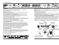
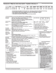
INTERNATIONAL LIMITED WARRANTY
ARX Systems (ARX) warrants to the first purchaser of any ARX equipment that it is free
from defects in materials and workmanship under normal use and service. ARX’s sole
obligation under this warranty shall be to provide, without charge, parts and labour
necessary to remedy defects, if any, which appear within twelve (12) months from date of
purchase, and for a further twelve (12) months supply parts only.
This is our only warranty. It does not cover finish or appearance items, burned voice
coils, or if the equipment has been, in ARX’s sole judgement:
•Subjected to misuse, abuse, negligence or accident;
•Repaired, worked on, or altered by persons not authorized by ARX;
•Connected, installed, adjusted or used for a purpose other than that for which it was
designed. This includes running a speaker system with the ISC leads disconnected, or
with a non-ARX crossover, or with the wrong processor.
LSP-2
Concert Series
Speaker Processor
This warranty gives you and us specific legal rights and you may also have other rights
which may apply.
Warranty Service Procedure
Should it become necessary to have your equipment serviced under the
terms of the warranty, please follow these steps:
1. Call your ARX distributor for a Return Authorization (RA) number;
2. Carefully repack the unit, in its original packaging where possible,
including a note with a description of the problem, and a copy of
the receipt showing date of purchase. Attach these to the actual
unit itself. Don’t forget to write your name and address clearly, and
include a phone number where you can be contacted during
normal business hours. Make it easy for our service technicians to
contact you if they have a question. Also, use plenty of packing
material - better to be safe than sorry.
3. Send the unit freight prepaid to ARX Systems, at the address given
you with your RA number. We will pay the return freight when the
serviced unit is returned to you.
4. We strongly recommend you insure the package. We can’t fix it if it
gets lost! Send it by UPS, Fedex, or any similar service that can track
the package. Parcel Post is not recommended
If Warranty Registration Card is missing, please write to ARX in the country of
purchase, stating model and where purchased, or to ARX, PO Box 15, Cheltenham,
Victoria 3192, Australia.
Or you can Email us at: [email protected]
8
LSP-2 Speaker Processor Owner's Manual v 2.2 CE ©2000 ARX®
OWNER’S
MANUAL
ARX Systems Pty Ltd, PO Box 15,
Cheltenham, Victoria 3192, Australia
Phone: 03 - 9555 7859 Fax: 03 - 9555 6747
International Fax: +61-3 -9555 6747
On the Web: http://www.arx.com.au
Email: [email protected]
LSP-2 Speaker Processor Owner's Manual v 2.2 CE ©2000 ARX®
IMPORTANT - PLEASE READ THIS FIRST
This is a dual voltage unit. It is essential that you check that the voltage on
the fuseholder cover below the AC connector on the rear of the chassis is
set correctly before connecting it to AC power.
THIS IS SET FOR
100 V AC TO 120 V
AC OPERATION
THIS IS SET FOR
220 V AC TO 240 V
AC OPERATION
To change, pull fuseholder out and rotate 180o, then push in again. Do not
insert power cable into unit until voltage has been correctly set. Do not plug
power cable into AC power until voltage has been correctly set
WARNING SYMBOLS USED ON THIS EQUIPMENT
This symbol is intended to alert you to the presence of important
operating instructions contained in this owner's manual
This symbol is intended to alert you to the presence of uninsulated
dangerous voltage within the product's enclosure that may be of
sufficient magnitude to constitute a risk of electric shock.
This symbol indicates that a Slow Blow fuse is used in this equipment. Replace with same type and value only
Complies with 89/336/EEC EMC Directive,
amended by 92/31/EEC and 93/68/EEC and
meets the following standards:EN 55013 :
1990, Sections 3.2 and 3.5 EN 55020 :
1988, Sections 4.3, 5.4, 6.2, 7.0, 8.0.
Complies with Australian Standard AS/N25
1053
2
LSP-2 Speaker Processor Owner's Manual v 2.2 CE ©2000 ARX®
LSP 2 Specifications
Input Impedance
Maximum Input Level
Input Level Control
CMRR
Output Impedance
(Band 1 & Band 2 output)
20Kohms Electronically balanced
+20dB
infinity – 0dB (no gain)
>50dB @ 1KHz
300 ohms Balanced
150 ohms Unbalanced
Maximum Output Level
+22dB
Low Output Level Control
infinity – +6dB (gain)
Signal to Noise Ratio
–96dB Band 1 output
–93dB Band 2 output
Frequency Response
20Hz—20KHz summed
Dynamic Range
118dB Band 1 output
115dB Band 2 output
Distortion (THD)
<.004%
Crossover Frequency
Dependent upon loudspeaker model
Crossover Filter Type
Linkwitz Riley 24dB per octave
High Pass Filter
Dependent upon loudspeaker model;
Modified Butterworth type, 24dB per
octave
High Frequency Equalisation Variable, dependent upon loudspeaker
model
ISC Returns
20K ohms Differential Input
ISC Return Connector Type
2 x Male 6 Pin Socket.
Pins 1 & 2 Low return
Pins 3 & 4 High return
Input /Output Connector type XLR
Power Requirements
100–120, 220–240 VAC, 50-60 Hz, 5 VA
Weight
5 lbs/2.2 Kg
Dimensions
19"W x 1¾"H x 6"D, 482 x 44 x 155mm
LSP-2 Speaker Processor Owner's Manual v 2.2 CE ©2000 ARX®
7
Front Panel controls
Model LEDs
One of this group of LEDs light up to show which Plug-in card is installed in
Channel A, and that the unit is connected to AC power.
Channel A level trim
These controls let you adjust the input level to the unit. During normal operation it
is set at the maximum (10) position.
Note: this is an attenuator only, not a gain control. Setting this level too low may
reduce the headroom in the preceding equipment.
All remaining controls are recessed behind an acrylic security cover to prevent
unauthorized access. Unscrew the knurled nut at each end of the cover and lift off
to make adjustments. Replace security cover afterwards.
Band 1 (the Lower filter) control
This control determines the Low Frequency output of your system. During normal
operation it is set at the 0dB (unity) position (12 o’clock). It also provides up to +6 dB
of gain past unity. This can be used for 2 purposes:
1. To achieve an increase in Low frequencies in relation to the Highs
2. Level compensation for amplifiers with differing input sensitivities
Input A: Connect signal feed from the Console here
Output Band 1 (LF) A: Connect the signal feed to the Lower Frequency Power Amp
here
Output Band 2 (HF) A: Connect the signal feed to the Higher Frequency Power
Amp here. Channel B connections identical
Connecting the ISC leads (Important!)
The White and Blue ISC leads, on 6 pin XLR connectors, plug into the corresponding sockets on the rear of the Control Unit.
These leads allow the LSP-2 to monitor the output of the amplifiers, and to activate
the protection circuits if the power exceeds the maximum safe operating area of the
speaker. The unit won’t turn on until you make these connections!
• The WHITE leads connect to the OUTPUTS of the LOW amplifiers, in parallel
with the leads going to the LOW speakers. The BLUE leads connect to the Outputs
of theHIGH amplifier, in parallel with the leads going to the HIGH speakers.
• Don’t get these mixed up as you will end up with the LOW ISC controlling the
HIGHs, and vice versa, which can cause major speaker damage to the HIGH
drivers.
• Make sure that the Channel A ISC leads are connected to the Channel A amplifi-
Band 1 Signal/ISC LEDs
The Signal LED shows you that some signal is running through the LSP-1. The ISC
LED indicates that the ISC protection circuitry is operating on the Low (Band 1)
output. During normal operation this LED will light up on transients or peaks if the
system is being used to achieve high SPL. This is normal, and should not be taken as
an indication that the system is being overdriven. However, if this LED is on for the
majority of the time, then the Low level is too high and should be reduced.
Channel A Input from
console (or LSP-1 Loop
outputs)
6 pin ISC
connector for
Channel A
Band 2 (the Higher filter) control and Signal/ISC LEDs
Same as for Band 1(Lower) but applicable to the Higher filter
VHF level trim control
This control determines the Very High Frequency energy output of your system. It
provides control from -12 dB (Hard LEFT) through to 0 dB/unity (Hard RIGHT). It
should be set in the 0 dB position for a flat response, but for a more musical response
you can rotate it anti-clockwise until the desired roll off is achieved.
Channel B controls are identical in operation
Channel A Band 1
(Low) and Band 2
(High) Outputs
To Low and High
amplifier inputs
Channel A
Channel A Low and
High ISC return leads
back to LSP-2
Rear Panel Connections
Only Channel A connections shown
in diagram. Channel B connections
identical but omitted for clarity
4
LSP-2 Speaker Processor Owner's Manual v 2.2 CE ©2000 ARX®
To High speaker
To Low speaker
LSP-2 Speaker Processor Owner's Manual v 2.2 CE ©2000 ARX®
5
ers, and Channel B leads to the Channel B amplifiers, or you will end up with the
Channel A ISC controlling Channel B and vice versa, which can give very strange
results.
• Work slowly and carefully, and take the time to get it right. It’s a good idea to
mark all leads as you go, so you can visually check all connections before powering
up.
Plug-In Parameter card modules
The LSP-2 2way Loudspeaker Processor is a general non-Model-specific Loudspeaker Management Platform.
The variable parameters required for each model, such as High Pass Filter, Frequency Response Contour, Phase Response, High Frequency Equalisation (LSP-2 only)
and Loudspeaker Component Power Handling Limits are all set on our new “Plug
in Card” system.
Each ARX Loudspeaker model now has its own dedicated Preset Card, ensuring
predictable performance and the ability to update Loudspeaker Performance simply
by plugging in new PCB cards.
This ‘user-friendly’ innovation enables easy re-configuration for different ARX
Loudspeaker models without the need to remove and replace components on the
unit’s Printed Circuit Board.
The LSP-2 Loudspeaker Processor can also be supplied calibrated to other manufacturer's (non ARX) speaker systems. For full details see our “Custom Plug-In Card
Technical Parameters’ fact sheet.
The following Model numbers apply:
Loudspeaker Model
Processor Platform & required Module Card
for 922 Loudspeakers order
LSP-2/M922
for 212 Loudspeakers order
LSP-2/M212
for 215 Loudspeakers order
LSP-2/M215
for 212 Loudspeakers order
LSP-2/M222
for user defined system order
LSP-2/MOPEN
The module cards are also available separately and can be ordered by using the
following model numbers:
for 922 Loudspeakers order
for 212 Loudspeakers order
for 215 Loudspeakers order
for 212 Loudspeakers order
for user defined system order
M922
M212
M215
M222
MOPEN
Introduction
Thank you for choosing this ARX speaker system. We understand that you are keen
to use your new purchase, but before you do, and to ensure continued trouble free
use, please familiarise yourself with the contents of this owner's manual before
plugging any leads in or connecting up to AC power.
In particular, pay close attention to the section on connecting the I.S.C. leads to the
processor. The colour code and channel selection is particularly critical when
putting the system together for the first time. Severe speaker damage can be caused by
incorrect wiring, and is not covered by the terms of your warranty. So please, take it
easy and check things as you go.
What is I.S.C?
I.S.C stands for Interactive System Control, ARX’s innovative Speaker and Electronics Interface.
There is a lot of hyperbole attached to the
Electronic Processing of speaker systems,
but if we look at what’s happening in an
purely audio electronics context, we find
that irrespective of the name attached to this
style of Speaker System they all basically
perform the same functions.
The Basic Principles of Feedback
style Gain Control
ISC monitors the output of the power amplifier driving each set of Loudspeaker
components and compares this signal with an internal model of the SOA (safe
operating area) of the driver. When the signal applied to the driver tries to exceed
that SOA, the signal is limited or held at a level which is safe for the driver to
reproduce. As the driver signal forms part of a feedback style loop this SOA can
never be exceeded.
Why monitor the outputs of the amplifiers?
What interests us is the actual power being applied to loudspeaker components, not
the signal being applied to the input of the Power Amplifier. To measure this
accurately and allow the user their personal choice in Power Amplifiers we have to
go where the action is - the outputs of the amplifier. This is used as the reference.
What size amplifier do I need?
You’ll notice that on all ARX speaker system spec sheets we quote a “recommended
minimum amplifier size” - we don’t quote power handling. The ISC processor
determines the amount of power supplied to each speaker, ensuring this remains
within the SOA of the driver. But by recommending the minimum amplifier size we
are indicating that this is the least amount of available power required for ISC to
operate in the way it was designed by ARX engineers.
Where do I put the processor?
The processor is mounted with the Amplifiers in the amp rack. In most applications
once the main frequency response balance is set, system equalization is achieved by
a Graphic or Parametric Equalizer, so there is no need to constantly access the
processor.
6
LSP-2 Speaker Processor Owner's Manual v 2.2 CE ©2000 ARX®
LSP-2 Speaker Processor Owner's Manual v 2.2 CE ©2000 ARX®
3