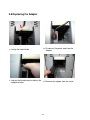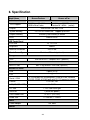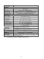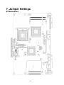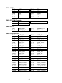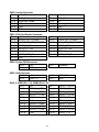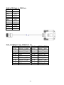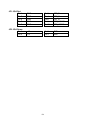
1
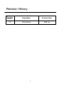
User Manual Breeze AllAll-inin-one Hardware System Copyright July 2008 All Rights Reserved Manual Version 1.0 The information contained in this document is subject to change without notice. We make no warranty of any kind with regard to this material, including, but not limited to, the implied warranties of merchantability and fitness for a particular purpose. We shall not be liable for errors contained herein or for incidental or consequential damages in connection with the furnishing, performance, or use of this material. This document contains proprietary information that is protected by copyright. All rights are reserved. No part of this document may be photocopied, reproduced or translated to another language without the prior written consent of the manufacturer. TRADEMARK Intel®, Pentium® and MMX are registered trademarks of Intel® Corporation. Microsoft® and Windows® are registered trademarks of Microsoft Corporation. e-Turbo Touch is the registered trademark of e-turbo Touch Systems. 2 Safety IMPORTANT SAFETY INSTRUCTIONS 1. To disconnect the machine from the electrial power supply, turn off the power switch and remove the power cord plug from the wall socket. The wall socket must be easily accessible and in close proximity to the machine. 2. Read these instructions carefully. Save these instructions for future reference. 3. Follow all warnings and instructions marked on the product. 4. Do not use this product near water. 5. Do not place this product on an unstable cart,stand,or table.The product may fall, causing serious damage to the product. 6. Slots and openings in the cabinet and the back or bottom are provided for ventilation;to ensure reliable operation of the product and to protect it from overheating. These openings must not be blocked or covered.The openings should never be blocked by placing the product on a bed, sofa, rug, or other similar surface.This product should never be placed near or over a radiator or heat register,or in a built-in installation unless proper ventilation is provided. 7. This product should be operated from the type of power indicated on the marking label.If you are not sure of the type of power available, consult your dealer or local power company. 8. Do not allow anything to rest on the power cord. Do not locate this product where persons will walk on the cord. 9. Never push objects of any kind into this product through cabinet slots as they may touch dangerous voltage points or short out parts that could result in a fire or electric shock. Never spill liquid of any kind on the product. CE MARK This device complies with the requirements of the EEC directive 89/336/EEC with regard to “Electromagnetic compatibility” and 73/23/EEC “Low Voltage Directive”. FCC This device complies with part 15 of the FCC rules. Operation is subject to the following two conditions: (1) This device may not cause harmful interference. (2) This device must accept any interference received, including interference that may cause undesired operation. 3 CAUTION ON LITHIUM BATTERIES There is a danger of explosion if the battery is replaced incorrectly. Replace only with the same or equivalent type recommended by the manufacturer. Discard used batteries according to the manufacturer’s instructions. LEGISLATION AND WEEE SYMBOL 2002/96/EC Waste Electrical and Electronic Equipment Directive on the treatment, collection, recycling and disposal of electric and electronic devices and their components. The crossed dustbin symbol on the device means that it should not be disposed of with other household wastes at the end of its working life. Instead, the device should be taken to the waste collection centers for activation of the treatment, collection, recycling and disposal procedure. To prevent possible harm to the environment or human health from uncontrolled waste disposal, please separate this from other types of wastes and recycle it responsibly to promote the sustainable reuse of material resources. Household users should contact either the retailer where they purchased this product, or their local government office, for details of where and how they can take this item for environmentally safe recycling. Business users should contact their supplier and check the terms and conditions of the purchase contract. This product should not be mixed with other commercial wastes for disposal. 4 Revision History Revision Number Description Revision Date 1.0 Initial release 2008 July 5 Table of Contents 1. Item Checklist...................................................................................................................... 7 1.1 Standard Item ................................................................................................... 7 1.2 Optional Item .................................................................................................... 8 2. System View......................................................................................................................... 9 2.1 Front View......................................................................................................... 9 2.2 Rear View ......................................................................................................... 9 2.3 I/O View …………………………………………………………………………….10 3. Drivers Installation ............................................................................................................11 3.1 Driver List ....................................................................................................... 11 3.2 Chipset Driver Installation ............................................................................... 11 3.3 USB 2.0 Driver Installation OS Requirements ................................................ 13 3.4 VGA Driver Installation.................................................................................... 16 3.5 POSTouch Driver Installation .......................................................................... 17 3.6 ELO Touch Driver Installation ......................................................................... 20 3.7 10/100/1000MB LAN Driver Installation.......................................................... 23 4. System Installation............................................................................................................ 24 4.1 Stand Holder Installation ................................................................................. 24 4.2 VFD Installation .............................................................................................. 26 4.3 MSR Installation.............................................................................................. 27 4.4Power Cord Installation.................................................................................... 28 4.5 VESA Installation for Panel display................................................................. 29 4.6 Cash Drawer Installation................................................................................. 30 5. System Disassembly .......................................................................................................... 32 5.1 Removing the Stand ....................................................................................... 32 5.2 Replacing the HDD ......................................................................................... 33 5.3 Replacing the Heat sink / Fan......................................................................... 34 5.4 Replacing the SDRAM.................................................................................... 35 5.5 Replacing the Main Board and PS2 board...................................................... 36 5.6 Replacing the Touch Board and inverter board............................................... 37 5.7 Replacing the Speaker.................................................................................... 38 5.8 Replacing the Adapter .................................................................................... 39 6. Specification........................................................................................................................... 40 7. Jumper Settings..................................................................................................................... 42 8.BIOS Settings ......................................................................................................................... 51 6 1. Item Checklist Take the system unit out of the carton. Remove the unit from the carton by holding it by the foam inserts. The following contents should be found in the carton: 1.1 Standard Items a. Driver CD b. Com port Cable (2) c. Power Cable d. Power Adapter e. System 7 1.2 Optional Items a. MSR + Finger Print Module b. VFD Customer Display c. Wall mount kit 8 2. System View 2.1 Front View Touch Screen AC Adapter in the stand 2.2 Rear View Vent Hole HDD Door VESA Mount Power Button Handle 9 2.3 I/O View Power Switch DC-IN LAN Cash Drawer Mic- in Line-out PS/2 2nd VGA COM1,2,3,4 10 USB Parallel 3. Drivers Installation 3.1 Driver List Folder/File File Description <CD>:\Breeze.htm Breeze Driver List <CD>:\COMMON\INTEL\Chipset Chipset Driver <CD>:\COMMON\INTEL\USB 20 <CD>:\COMMON\INTEL\VGA\i85x USB 2.0 Driver VGA Driver <CD>:\COMMON\POS_Touch POSTouch Driver <CD>:\COMMON\ELO_Touch ELO Touch Driver <CD>:\COMMON\Lan_driver\Realtek_PCI 10/100/1000MB LAN Driver -The following procedures are for Windows 2000/XP, other platforms are similar. 3.2 Chipset Driver Installation a. Double click “infinst_enu_6.0.1.1002” on the My computer window. b. Click the “Next” button on the Welcome window. 11 c. Click the “Yes” button on the License Agreement window. d. Click the ”Next” button on the Readme Information window. e. Click the “Finish” button and restart your system. 12 3.3 USB 2.0 Driver Installation OS Requirements OS USB 2.0 requirements Windows XP USB 2.0 drivers are provided in Service Pack 1 (SP1) for Windows XP, which is available through Windows Update. Windows 2000 USB 2.0 drivers are available through Windows Update or Service Pack 4. Windows 98SE/Me USB 2.0 drivers are available on the Intel developer site. Windows 98 (Retail) Developers and OEMs should contact Orange Ware. For end-users, if your device does not ship with Windows 98 drivers, contact your device or system manufacturer. If USB 2.0 drivers are not available, your device will operate at USB 1.1 speeds Linux USB 2.0 support is available in kernel 2.4.19 or later development kernels, or in the 2.4.19 or later production kernel. More information. a. Right click My Computer on the desktop and select “properties” b. Select “Hardware””Device Manager” on system properties. 13 c. Select ”Other Devices” “Universal Serial Bus (USB) Controller” ”Properties” on Device Manager. d. Select “Device” “Update Driver…”. e. Click the ”Next” button on the welcome window. f. g. Select “Specify a location” and click the “Next” button on the Locate Driver Files window. Select “Search for a suitable…”and click the “Next” button on the Install Hardware Device Drivers window. 14 h. Press “Browse” to select the driver and then click the “OK” button to go to the next page. i. j. k. Finished. Click the “Finish” button to complete this process. 15 Click the “Next” button on the Driver Files Search Results window. 3.4 VGA Driver Installation a. Double click “win2k_xp147” on the My Computer window. b. Click the “Next” button on the Welcome window. c. Click the ”Next” button on the Welcome window. d. Click the ”Yes” button on the License Agreement window. e. Click the ”Finish” button and restart your system. 16 3.5 POSTouch Driver Installation a. Double click the ”Setup” on the “My Computer” window. b. Click the “Next“ button on the “Welcome window”. c. Click the ”Yes” button on the “License Agreement” window. d. Click the ”Next” button on the “Choose Destination Location” window. e. Click the “Next” button on the “Select Program Folder” window. f. Click the “Finish” button on the “Install Shield Wizard Complete” window. 17 g. Click the “Continue Anyway “button on the “Hardware Installation” window. h. Select the “Yes” and click the”OK” button and restart your system. i. After the computer has restarted, select “Programs TouchUtility Scan RS232 Touch Device”. j. The serial ports are scanned for a touch device. k. Select “Programs TouchUtility Touch Utility”. l. Click “Scale / Offset” on the POSTouch Utility window. 18 m. Follow the instructions on the screen to do a three point calibration of the touch panel. n. Select “Device 9Pts Calibration” on the POSTouch Utility window. o. Follow the instructions on the screen to do a nine point calibration of the touch panel. 19 3.6 ELO Touch Driver Installation a. Click ”sw500930” on the My computer window. b. Click the “OK” button on the Welcome window. c. Click the ”Unzip” button on the WinZip Self-Extractor window. d. Select “Install Serial Touchscreen Drivers” and then click the “Next” button on the Welcome window. 20 e. Click the “Yes” button on the License Agreement window. f. g. Select “COM5” and click the “Next” button on the Choose the COM ports… window. h. Click the “Next” button on the You have selected the COM ports…window. 21 Click the “Next” button on the on the “Select the COM ports…” window. i. Click the “Finish” button on the Setup Complete window k. After the computer has restarted, click “Align” on the Elo Touchscreen Properties window. j. Click the “Yes” button and restart your system. l. Follow the instructions on the screen to calibrate the touch panel. 22 3.7 10/100/1000MB LAN Driver Installation a. Double click ”Setup” on the My Computer window. b. Click the “Finish” button on the Maintenance Complete window. c. Click the ”OK” button and restart your system. 23 4. System Installation 4.1 Stand Holder Installation a. Slide the stand bracket into the position b. Fix VESA and stand with screws (6) 3 on each side c. Attach the panel to the stand bracket 24 d. Tighten the thumbscrew (1) e. Attach the hinge covers(2) to the side of each hinge 25 4.2 VFD Installation a. Slide the VFD module to the system VESA bracket and tighten it with the thumb screw b. Connect the VFD cable to the COM port and the VFD module 26 4.3 MSR Installation a. Loosen the screws (2) on the MSR dummy cover b. Connect the MSR cable and slide the MSR into position c. Connect the MSR module to the system and tighten the screws (3) 27 4.4 Power Cord Installation a. Connect the power cord to the AC adaptor b. Fasten the cable withb the clip tom ensure the cable is in the proper location. c. Route through the base gap for cable management 28 4.5 VESA Installation for Panel display If you wish to wall mount the POS Terminal, please order the wall mount kit from your supplier and follow the steps below to install the wall mount display unit.. a. Remove stand by loosening thumbscrew (1) and remove the stand b. Place the wall mount kit on the panel bracket and tighten the screw (1) c. Attach the wall mount bracket and tighten it with the thumbscrew (1) 29 4.6 Cash Drawer Installation You can install a cash drawer through the cash drawer port. Please verify the pin assignment before installation. Cash Drawer Pin Assignment 6 Pin 1 2 3 4 5 6 1 Signal GND DOUT bit0 DIN bit0 12V / 19V DOUT bit1 GND Cash Drawer Controller Register The Cash Drawer Controller use one I/O addresses to control the Cash Drawer. Register Location: 4B8h Attribute: Read / Write Size: 8bit BIT BIT7 BIT6 BIT5 BIT4 BIT3 Attribute Reserved Reserved Reserved Read BIT2 BIT1 BIT0 Reserved Write Write Reserved 7 6 5 4 3 2 1 0 X X X X X Reserved Cash Drawer “DOUT bit1” pin output control Cash Drawer “DOUT bit0” pin output control Cash Drawer “DIN bit0” pin input status Reserved Bit 7: Reserved. Bit 6: Reserved. Bit 5: Reserved. Bit 4: Cash Drawer “DIN bit0” pin input status. = 1: the Cash Drawer closed or no Cash Drawer. = 0: the Cash Drawer opened. Bit 3: Reserved. 30 Bit 2: Cash Drawer “DOUT bit0” pin output control. = 1: Opening the Cash Drawer = 0: Allow closing the Cash Drawer Bit 1: Cash Drawer “DOUT bit1” pin output control. = 1: Opening the Cash Drawer = 0: Allow closing the Cash Drawer Bit 0: Reserved Note: Please follow the Cash Drawer control signal design to control the Cash Drawer. Cash Drawer Control Command Example Use Debug.EXE program under DOS or Windows98 Command Cash Drawer O 4B8 04 Opening O 4B8 00 Allow to closing Set the I/O address 4B8h bit2 =1 for opening the Cash Drawer by “DOUT bit0” pin control. Set the I/O address 4B8h bit2 = 0 to allow closing Cash Drawer. Command I 4B8 Cash Drawer Check status The I/O address 4B8h bit4 =1 means the Cash Drawer is closed or no Cash Drawer. The I/O address 4B8h bit4 =0 means the Cash Drawer is open. 31 5. System Disassembly 5.1 Removing the Stand a. Loosen the thumbscrew (1) b. Lift the panel up and separate it from the stand 32 5.2 Replacing the HDD a. Loosen the screw * 1 b. Open the HDD door c. Lift the HDD up from the holder 33 5.3 Replacing the Heat sink / Fan a. Loosen the thumbscrews *2 b. Pull the handle in the direction shown by the arrow in order to release the mainboard tray from the system Cooler kit for fanless system Cooler kit for socket type CPU c. Loosen the screw *4 and disconnect the cable *1 to replace the heat sink / fan 34 5.4 Replacing the SDRAM To replace the main board, please first follow the steps in chapter 5.3 a / b. a. Use your finger to push the DIMM slot ejector clips into the down position. b. Remove the SDRAM from the slot in the direction as shown by the arrow to replace it 35 5.5 Replacing the Main Board and PS2 board To replace the main board, please first follow the steps in chapter 5.3 a / b. a. Remove the hex nuts *6 b. Remove the screws (6) from the holder bracket of both sides Remove the PS2 board a. Disconnect the cable (1) b. Remove the screws(2) from the I/O bracket then remove the PS/2 board. 36 5.6 Replacing the Touch Board and inverter board To replace the touch board and inverter board, please follow the step in chapter 5.1 to remove the LCD display module from the stand chapter 5.2 to replace HDD. a. Remove LCD cover by loosening the screws (6) b. Loosen the screw (7) to remove the EMI shielding cover To replace the touch board a. Disconnect the cables (2) and remove the screws (2) to replace the touch board 37 To replace the inverter board c. Disconnect the cables (3) d. remove the screws (2) to move the inverter board 5.7 Replacing the Speaker To replace the speakers, please first follow the steps 5.1 and 5.6 step a. Disconnect the cable (1) and remove the screws 4) to remove the speakers (2) 38 5.8 Replacing the Adapter a. Unclip the cable holder b. Disconnect the power cord from the adaptor c. Loosen the thumbscrew to release the adaptor bracket d. Remove the adaptor from the stand 39 6. Specification Model Name Breeze Fanless B78 Motherboard CPU Support Chipset System Memory Graphic Memory Breeze w/Fan Intel Celeron M ULV Intel Celeron M 1.5GHz / 1.0GHz Zero Cache Pentium M 1.8GHz (socket) Intel 852GM FSB 400 / ICH4 2 x DDR SO-DIMM Slot support up to 2GB Shared system memory 8~64MB BIOS AWARD BIOS LCD Touch Panel LCD Size 15” TFT LCD Brightness 250nits Maximal Resolution 1024 x 768 Touch Screen Type Resistive / IR touch (optional) Storage HDD Slim SATA HDD / Compact flash ( optional ) Expansion Mini-PCI Slot 802.11 b/g wireless LAN card ( optional ) External I/O Ports USB 4 ports (V2.0) PS2 1 Serial / COM Parallel 4 x COM ports RJ-45 connectors (COM1&COM2 standard RS-232; COM3 & COM4 pin9 with 5V /12V power by jumper) 1 x D-sub / 25F LAN (10 /100 / 1000) 1 x RJ45 DC Jack 1 x DC Jack latch type 2nd VGA 1 (male with power ) Cash Drawer Port 1 x RJ 11 (12V /19V) Audio Jack 1 x Line-out, 1 x Mic-in Power Power Adapter 19V, 90W Control 40 Power Button 1 Peripheral MSR 2-in-1 MSR Second Display Customer Display MSR ( PS/2 ) MSR ( PS/2 ) / Finger Print (USB ) optional 8.4”/ 10.4’ / 12.1" 2nd display without touch Flush mount VFD display 2 x20 characters Environment EMC & Safety Operating Temperature Storage Temperature Operating Humidity FCC, Class A, CE, LVD 20% ~ 80% RH non condensing Storage Humidity 20% ~ 85% RH non condensing 5oC ~ 35 oC (41 oF ~ 95 oF) -20 oC ~ 55 oC (-4 oF ~ 140 oF) Dust & Water Proof Dimension (W x D x H) IP 54 (Front bezel) LCD 0 degree :374.52 x 308.44 x 311 mm LCD 90 degrees :374.52 x 370.14 x 251.47 mm 9kg/ 10kg Weight (N.W./G.W.) 100mm x100mm VESA Standard holes Windows XP, WEPOS, XP Embedded, XP Professional OS Support Embedded, Windows 2000 Professional Embedded, WIN NT4.0, Embedded Linux * This specification is subject to change without prior notice. Mounting 41 7. Jumper Settings B78 Motherboard 42 Connectors Connector CN1 CN2 CN13 CN15 CN16 CN18 CN19 CN20 CN21 Function Audio Line Out Audio Mic In COM5 for Touch CPU FAN Connector Hardware Reset USB2 LCD Interface Connector Inverter Connector Card Reader Connector Connector IDE1 SATA1 PRN1 PWR1 RJ11_1 RJ45_1 RJ45_2 USB1 USB2 6.3 Jumper Settings CMOS Operation Mode Function JP8 CMOS Normal ◎N/C CMOS Reset 1-2 To clear the CMOS: Remove AC power from the unit. Open the cabinet. Change the JP8 jumper setting from N/C to 1-2. Wait 1 minute. Change the JP8 jumper setting back to N/C. Close the cabinet. Apply AC power and continue. Power Mode Setting Function JP6 ATX Power ◎N/C AT Power 1-2 43 Function Primary IDE Connector Primary SATA Connector Parallel Port +19V Power Adapter Cash Drawer Connector LAN (On Board) COM1, COM2, COM3, COM4 USB3, USB4 USB5, USB6 Cash Drawer Power Setting Voltage JP4 +12V ◎1-2 N/A 3-4 +19V 5-6 COM3 & COM 4 Power Setting Function JP3 COM3 PIN10_RI ◎1-2 COM3 PIN10_+5V 3-4 COM3 PIN10_+12V 5-6 COM4 PIN10_RI ◎7-8 COM4 PIN10_+5V 9-10 COM4 PIN10_+12V 11-12 Card Reader Setting Function ◎Docking On Board JP11 (1-2) N/C 1-2 JP11 (3-4) N/C 3-4 44 LCD ID Setting Panel Resolution # JP7 0= Short; 1= Open Supported panels Bits Channel 1-2 3-4 5-6 7-8 18 Single 0 0 0 0 LVDS 0 640 x 480 1 800 x 600 18 Single 0 0 0 1 2 1024 x 768 18 Single 0 0 1 0 3 1280 x 1024 24 Dual 0 0 1 1 4 1024 x 768 24 Single 0 1 0 0 5 800 x 600 24 Single 0 1 0 1 6 7 8 800 X 800 X 1024 X 600 600 768 18 18 24 Single Single Single 0 0 0 1 1 1 1 1 0 0 1 0 45 AU G121SN01 Sharp 12” LQ121S1LLG41 CHI MEI N121X5-L03) XGA CHI MEI G121X1-L01) XGA AU G150XG01 XGA IDTech IAXG02L5 XGA LTA121C250F-01 AU M150XN07 V1 AU 17" / 19" SHARP LQ150X1LGN1 SHARP LQ150X1LGN2 AU M150XN07 V.2 AU G150XG03 V.0 24bit Sharp LQ150X1LG55 24bit Sharp LQ150X1LG45 24bit Torisan 12.1” L5S30548P00 Reserved Sharp 12” LQ121S1LLG41 SVA150XG10TB COM2 RS232 ◎RS232 Function JP9 (1-2) V JP9 (3-4) V JP9 (4-6) JP9 (5-7) V JP9 (7-8) JP9 (9-10) JP10 (1-2) V JP10 (3-4) JP10 (5-6) JP10 (7-8) JP10 (9-10) JP10 (11-12) Note: OPEN SHORT Connectors Pin Definition CN4: Speaker & MIC Connector Pin 1 AMP_ORL Pin 3 GND Pin 5 GND Pin 2 Pin 4 Pin 6 GND AMP_ORR MIC1 CN9: CD-IN Connector Pin 1 CDIN_L Pin 3 CDIN_R Pin 2 Pin 4 CDIN_REF CDIN_REF CN11: Power Connector For 3.5” HDD Pin 1 +12V Pin 3 GND Pin 2 Pin 4 GND +5V 46 CN13: COM5 Pin 1 Pin 3 Pin 5 Pin 7 Pin 9 DCD# TX# GND RTS# RI CN15: CPU FAN Connector Pin 1 +5V Pin 3 GND CN18: USB 2 Pin 1 Pin 3 +5V_USB1 USB20_R_P1+ CN19: LVDS Interface Pin 1 LVDS_B0+ Pin 3 LVDS_B0Pin 5 GND Pin 7 LVDS_B1+ Pin 9 LVDS_B1Pin 11 GND Pin 13 LVDS_B2+ Pin 15 LVDS_B2Pin 17 GND Pin 19 LVDS_B3+ Pin 21 LVDS_B3Pin 23 GND Pin 25 LVDS_CLKB+ Pin 27 LVDS_CLKBPin 29 GND Pin 31 +5V_LCDVDD Pin 33 +5V_LCDVDD Pin 35 +5V_LCDVDD Pin 37 +5V_LCDVDD Pin 39 +5V_LCDVDD 47 Pin 2 Pin 4 Pin 6 Pin 8 Pin 10 RX# DTR# DSR# CTS# +5V Pin 2 Feedback Pin 2 Pin 4 USB20_R_P1 GND Pin 2 Pin 4 Pin 6 Pin 8 Pin 10 Pin 12 Pin 14 Pin 16 Pin 18 Pin 20 Pin 22 Pin 24 Pin 26 Pin 28 Pin 30 Pin 32 Pin 34 Pin 36 Pin 38 Pin 40 LVDS_A3+ LVDS_A3GND LVDS_CLKA+ LVDS_CLKAGND LVDS_A2+ LVDS_A2GND LVDS_A1+ LVDS_A1GND LVDS_A0+ LVDS_A0GND +3.3V_LCDVDD +3.3V_LCDVDD +3.3V_LCDVDD +3.3V_LCDVDD +3.3V_LCDVDD CN20: Inverter Connector Pin 1 +12V_INV Pin 3 +12V_INV Pin 5 Back-Light Enable Pin 7 N/C Pin 9 GND Pin 11 GND CN21: POS Card Reader Connector Pin 1 +5V Pin 3 KDATA_SIO_TO_MSR Pin 5 KDATA_MSR_TO_GFINGER Pin 7 RS232_6_RX# Pin 9 RS232_6_CTS# Pin 11 KB_EN Pin 13 USB20_MSR_P0+ Pin 15 GND CN22: System FAN Connector Pin 1 +5V Pin 3 GND CN23: IrDA Connector Pin 1 +5V Pin 3 IRDA_TX Pin 2 Pin 4 Pin 6 Pin 8 Pin 10 Pin 12 +12V_INV +12V_INV N/C Back-Light Enable GND GND Pin 2 Pin 4 Pin 6 Pin 8 Pin 10 Pin 12 Pin 14 +5V KDATA_SIO_TO_MSR KCLK_MSR_TO_GHINGER RS232_6_TX# RS232_6_RTS# GND USB20_MSR_P0- Pin 2 Feedback Pin 2 Pin 4 IRDA_RX GND RJ45_2: COM1(Pin1~10), COM2 (Pin11~20) Pin 1 N/C Pin 2 Pin 3 RS232_1_DSR# Pin 4 Pin 5 RS232_1_RTS# Pin 6 Pin 7 RS232_1_CTS# Pin 8 Pin 9 GND Pin 10 Pin 11 N/C Pin 12 Pin 13 RS232_2_DSR# Pin 14 Pin 15 RS232_2_RTS# Pin 16 Pin 17 RS232_2_CTS# Pin 18 Pin 19 GND Pin 20 48 RS232_1_DCD# RS232_1_RX# RS232_1_TX# RS232_1_DTR# RS232_1_RI RS232_2_DCD# RS232_2_RX# RS232_2_TX# RS232_2_DTR# RS232_2_RI RJ45 to DB9 Cable for COM Ports RJ45 DB9 Pin 1 --Pin 2 Pin 1 Pin 3 Pin 6 Pin 4 Pin 2 Pin 5 Pin 7 Pin 6 Pin 3 Pin 7 Pin 8 Pin 8 Pin 4 Pin 9 Pin 5 Pin 10 Pin 9 RJ45_2: COM3(Pin21~30), COM4(Pin31~40) Pin 21 N/C Pin 22 Pin 23 RS232_3_DSR# Pin 24 Pin 25 RS232_3_RTS# Pin 26 Pin 27 RS232_3_CTS# Pin 28 Pin 29 GND Pin 30 Pin 31 N/C Pin 32 Pin 33 RS232_4_DSR# Pin 34 Pin 35 RS232_4_RTS# Pin 36 Pin 37 RS232_4_CTS# Pin 38 Pin 39 GND Pin 40 49 RS232_3_DCD# RS232_3_RX# RS232_3_TX# RS232_3_DTR# RS232_3_RI RS232_4_DCD# RS232_4_RX# RS232_4_TX# RS232_4_DTR# RS232_4_RI JP1: VGA Port Pin 1 Pin 3 Pin 5 Pin 7 Pin 9 GND GND GND GND GND Pin 2 Pin 4 Pin 6 Pin 8 Pin 10 CRT_R CRT_G CRT_B CRT_HSYNC CRT_VSYNC JP2: VGA Power Pin 1 Pin 3 +12 +12 Pin 2 Pin 4 GND GND 50 8.BIOS Settings 8.1 BIOS Setup Utility The BIOS setup defines how the system is configured. You need to run this program the first time you configure this product. You may need to run it again if you change the configuration. You need to connect a PC keyboard to the keyboard connector to run the BIOS setup utility. 8.2 Starting the BIOS Setup 1. Turn on or reboot this product. 2. Press the DEL key immediately after the product is turned on, or press the DEL key when the following message is displayed during POST (the Power on Self-Test). Press DEL to enter SETUP. 3. The main menu of the BIOS setup is displayed. 4. If the supervisor password is set, you must enter it here. 8.3 When a Problem Occurs If, after making and saving system changes with the Setup utility, you find that this product no longer boots, start the BIOS setup and execute the following. Load Optimized Defaults 8.4 BIOS Main Menu When the BIOS Main Menu is displayed, the following items can be selected. Use the arrow keys to select items and the Enter key to accept and enter the sub-menu. Note: The BIOS menu below is from B78 BIOS version B78FV10.BIN. If you have a different BIOS version, the contents of the menu may different. 51 Standard CMOS Features Use this menu for basic system configuration. Advanced BIOS Features Use this menu to set the Advanced Features available on the system. Advanced Chipset Features Use this menu to change the values in the chipset registers and optimize the system’s performance. Integrated Peripherals Use this menu to specify your settings for integrated peripherals. Power Management setup Use this menu to specify your settings for power management. PnP/PCI Configurations This entry appears if your system supports Plug and Play and PCI Configuration. PC health status Displays CPU, System Temperature, Fan Speed, and System Voltages Value. Load Optimized Defaults Use this menu to load the BIOS default values, i.e., factory settings for optimal performance system operations. While Award has designed the custom BIOS to maximize performance, the factory has the option to change these defaults to meet their needs. 52 Set Supervisor Password Enables you to change, set, or disable the supervisor or user password. Set Password Change, set, or disable the password. It allows you to limit access to the system and to the setup, or just to the setup. Save & exit setup Save CMOS value changes to CMOS and exits setup. Exit without saving Ignores all CMOS value changes and exits setup. 53