1
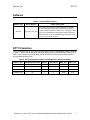
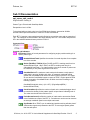
Engine Position Tracking VI
User’s Manual Supplement
For Start/Stop Encoder Pattern
D000038
Rev B
December 2010
Drivven, Inc. • 12001 Network Blvd • Bldg E, Ste 110 • San Antonio, Texas 78249 • USA
Phone : 210.248.9308
Web : www.drivven.com , E-mail : [email protected]
Drivven, Inc.
EPT VI
Introduction
This document is a supplement to the EPT VI User Manual, and provides specific information
about the EPT Enc VI for handling Start/Stop conditions such that crankshaft position is tracked
during engine-stop reversals, and the position is known immediately upon starting again. The
functionality of the EPT ENCSS VI maintains as much similarity as possible with the EPT ENC VI
so that additional Drivven products may be interfaced directly with the FuelSparkSupervisor
output cluster.
This EPT VI has a new Boolean input to enable or disable the Start/Stop mode of operation.
When disabled, the EPT operates nearly identical to the standard version, such that in order to
achieve initial synchronization, the EPT must see a certain number of crank pulses before
searching for the indexing pulse. When enabled, the EPT must still gain initial sync similar to the
standard EPT, but after initial sync has been achieve, it will maintain the correct CrankCount and
CurrentPosition, even when stopped or rotated backwards. When crankshaft rotation starts in the
forward direction again, sync will be achieved immediately upon the first two EncA signals. This
allows engine synchronous outputs to be generated immediately after restarting crankshaft
rotation. Two-stroke and four-stroke engine cycles are supported for a 360 degree or 720-degree
range. If operated in four-stroke mode, then a cam phase signal must be used external to this VI
to gate every other EncZ signal. Below is a brief list of features of the EPT ENCSS VI.
Features:
¾ Accepts Encoder A, B and Z signals
¾ Detects and reports direction change, loss of EncA and EncZ signals
¾ Maintains CrankCount and CurrentPosition during engine stops and oscillations
¾ After Start/Stop mode is entered, achieves sync immediately upon start of rotation
¾ Start/Stop mode can be disabled for traditional mode of operation
¾ Supports 2-stroke and 4-stroke configurations
¾ Direction-change flag output available for higher level software interrupts
¾ Built-in encoder simulator for bench testing of actuators
© Drivven, Inc. 2010 • EPT VI User’s Manual Supplement for Start/Stop Encoder • Rev B
2
Drivven, Inc.
EPT VI
Software
Table 1. Supported EPT Patterns
Pattern Type
Encoder
EPT VI Names
Pattern Description
ept_encss_vte4_revb
The encoder attached to the crankshaft must be a standard
incremental optical encoder having quadrature encoding of
signals A and B along with a Z index pulse. The edges of the Z
signal must coincide with the edges of the B signal, and have
opposite polarity. The recommended range of encoder counts
per turn for this VI is 90 to 1800.
EPT VI Selection
There is a single FPGA VI for the EPT ENCSS pattern having an extrapolation of 4 bits, as shown
in Table 1. The recommended range of encoder pulses per turn (NumberOfCrankTeeth) is 90 to
1800. Table 2 shows the resulting MAX_CAT and CAD/CAT for the minimum and maximum
recommended pulses per turn.
Table 2. EPT VI Extrapolation Values and Suggestion Tooth Count Ranges
Pattern Type NumberOfCrankTeeth Stroke Extrapolation MAX_CAT CAD / CAT
Encoder (max)
1800
4
4
57600
0.01
Encoder (min)
90
4
4
2880
0.25
Encoder (max)
1800
2
4
28800
0.01
Encoder (min)
90
2
4
1440
0.25
© Drivven, Inc. 2010 • EPT VI User’s Manual Supplement for Start/Stop Encoder • Rev B
3
Drivven, Inc.
EPT VI
Sub VI Documentation
ept_encss_vte4_revb.vi
Engine Position Tracking VI
Pattern Type = Encoder with Start/Stop Mode
Extrapolation Level = 4 Bits.
To be placed within a single cycle loop of an FPGA block diagram, executed at 40 MHz.
See the Pattern-Specific Information in the EPT EncSS User Manual.
Each EPT VI requires a pre-synthesized netlist file having a matching name and an extension of
.ngc. The netlist file must be located in the same directory as the VI. The installer will place this
file in the LabVIEW addons directory with the FPGA VI.
Connector Pane
Controls and Indicators
EPTControl Cluster of control parameters for configuring engine position tracking for a
specific pattern type.
NumberOfCrankTeeth Specifies the number of encoder A pulses for a complete
turn of the encoder.
Stroke (FALSE=2, TRUE=4) When FALSE, the EPT is tracking teeth from 0 to
NumberOfCrankTeeth. When TRUE, the EPT is tracking teeth from 0 to
2*NumberOfCrankTeeth. For 4-stroke mode, every other encoder Z pulse must
be masked by a cam phase signal external to this VI.
CrankStallPeriod The maximum crank tooth period between evenly spaced
crank teeth in terms of 40 MHz clock ticks. A measured crank tooth period
greater than CrankStallPeriod causes the Period output of the EPT VI to report
as zero and the CrankStalled output to report as TRUE. Engine speed in RPM
can be converted to CrankStallPeriod in 40 MHz clock ticks according to the
following equation:
CrankStallPeriod(clock ticks) = (60 * 4E7) / (EngineSpeed(RPM) *
NumberOfCrankTeeth)
CrankCountStart Specifies the number of teeth on the crankshaft trigger wheel
to count before looking for the pattern-specific unique feature indicating tooth 0.
The value must be set with a minimum of 2.
PeriodAccumCount Specifies the number of crank teeth to accumulate Period
in the PeriodAccum output of the EPT VI. PeriodAccum can be used to measure
an average crankshaft speed over multiple crank teeth.
SyncEnable When TRUE, sync is enabled and position tracking will take place if
valid encoder signals are presented to the EPT VI at an engine speed greater
than the stall speed.
© Drivven, Inc. 2010 • EPT VI User’s Manual Supplement for Start/Stop Encoder • Rev B
4
Drivven, Inc.
EPT VI
StartStopEnable When TRUE, and SyncEnable and SSState are also TRUE,
sync is enabled and position tracking will take place upon each EncA pulse,
independent of speed, and in both forward and reverse directions.
DirPolarity FALSE: Direction = 0 (forward) when EncA rising edge occurs while
EncB is low
Direction = 1 (reverse) when EncA rising edge occurs while EncB is high
TRUE: Direction = 1 (reverse) when EncA rising edge occurs while EncB is low
Direction = 0 (forward) when EncA rising edge occurs while EncB is high
SimEnable When TRUE, the encoder signals within the EPTInSig cluster are
internally disconnected from the position tracking core and simulated signals are
connected in their place.
When simulation is disabled, the internal simulated encoder count and timing
parameters are halted and maintained in order to test the start/stop features of
the EPT VI.
MissedEncAFlagClr When TRUE, the MissedEncAFlag within the EPTData
cluster will be cleared.
MissedEncZFlagClr When TRUE, the MissedEncZFlag within the EPTData
cluster will be cleared.
DirRevFlagClr When TRUE, the DirRevFlag within the EPTData cluster will be
cleared.
SimPeriod The simulated period between evenly spaced crank teeth in terms of
40 MHz clock ticks. SimPeriod is only effective when it is set to a non-zero value
while SimEnable is TRUE. The EPT will not sync to the simulator unless the
effective engine speed is greater than the stall speed. Engine speed in RPM can
be converted to SimPeriod in 40 MHz clock ticks according to the following
equation:
SimPeriod(clock ticks) = (60 * 4E7) / (EngineSpeed(RPM) *
NumberOfCrankTeeth)
SimDirection During EPT simulation, this parameter determines the direction of
the simulated quadrature encoded signals.
FALSE: Specifies the forward direction
TRUE: Specifies the reverse direction
WatchdogIn The WatchdogIn Boolean signal must be toggled at a rate greater
than 4 Hz. The purpose of the watchdog is to shutdown engine position tracking
(as well as any engine synchronous outputs) in the case of a loss of LabVIEW
RT communication with the FPGA. For example, the LabVIEW RT application
may fail due to coding errors without properly closing the FPGA application. It
would not be desirable for the EPT to continue tracking engine position and
supervising engine synchronous outputs according to the last command received
from the LabVIEW RT application. The WatchdogIn can be toggled by a simple
NOT function and feedback node within LabVIEW RT.
© Drivven, Inc. 2010 • EPT VI User’s Manual Supplement for Start/Stop Encoder • Rev B
5
Drivven, Inc.
EPT VI
EPTInSig Cluster of optical encoder A, B and Z signals used by the EPT for tracking
free-piston position.
EncA The digital input signal representing the encoder A pulse train. The
EPTSS VI counts crank teeth on the forward rising edge of EncA or the reverse
falling edge of EncA.
EncB The digital input signal representing the encoder B pulse train. The EPT
VI uses EncB with respect to EncA for determining derection.
EncZ The digital input signal representing the encoder Z index pulse. The EPT
VI responds to the rising edge of EncZ.
FuelSparkSupervisor This cluster output must be wired directly to the
FuelSparkSupervisor cluster inputs of Drivven fuel and/or spark VIs.
EPTData Cluster of status information related to engine position tracking.
CrankSigOS A 40 MHz one-clock one-shot generated at the rising edge of each
received or simulated EncA input. This signal can be used in conjunction with
CrankCount for any purpose within LabVIEW FPGA logic to perform engine
synchronous tasks.
CrankStalled Set to TRUE when the engine speed is below stall speed.
SyncStopped Set to TRUE while position tracking is not taking place. In other
words, no sync.
MissedEncAFlag Set to TRUE upon the detection of a EncZ rising edge while
the CrankCount value has not yet reached the expected value. In other words,
the EncZ tooth has been detected sooner than expected. This condition causes
a loss of sync. Re-sync is not allowed until the flag is cleared by setting
MissedEncAFlagClr to TRUE.
MissedEncZFlag Set to TRUE upon CrankCount being incremented past the
expected value for the location of a EncZ rising edge before the EncZ rising edge
is detected. In other words, the EncZ was not received when expected. This
condition causes a loss of sync. Re-sync is not allowed until the flag is cleared
by setting MissedEncZFlagClr to TRUE.
DirRevFlag Set to TRUE upon a change of direction from forward to reverse.
When StartStopEnable is FALSE, this flag will cause a loss of sync. Re-sync is
not allowed until the flag is cleared by setting DirRevFlagClr to TRUE.
When StartStopEnable is TRUE, this flag will not cause a loss of sync. The flag
is cleared by setting DirRevFlagClr to TRUE.
Period The period between the last two crank trigger teeth, as if there were no
missing or extra teeth, in terms of 40 MHz clock ticks. Period will be set to 0
while Stalled is TRUE. Period in clock ticks can be converted to instantaneous
engine speed in RPM according to the following equation:
EngineSpeedInstant(RPM) = (60 * 4E7) / (Period * NumberOfCrankTeeth)
PeriodAccum The accumulated period over PeriodAccumCount crank teeth in
© Drivven, Inc. 2010 • EPT VI User’s Manual Supplement for Start/Stop Encoder • Rev B
6
Drivven, Inc.
EPT VI
terms of 40 MHz clock ticks. PeriodAccum will be set to 0 while Stalled is TRUE.
PeriodAccum in clock ticks can be converted to average engine speed in RPM
according to the following equation:
EngineSpeedAve(RPM) = (60 * 4E7) / (PeriodAccum * NumberOfCrankTeeth /
PeriodAccumCount)
CrankCount The latest tooth count referenced to crank tooth 0. Tooth 0 is the
first EncA pulse following the EncZ pulse during the phase 1 to phase 0 piston
stroke.
CurrentPosition During sync, the EPT provides the latest crankshaft position in
terms of absolute Crank Angle Ticks (CAT) over a complete engine cycle,
referenced to position 0. Position 0 is the first EncA pulse following the EncZ
pulse during the phase 1 to phase 0 piston stroke. The CurrentPosition in CAD
can be calculated according to the following:
CurrentPosition(CAD) = [CurrentPosition(CAT) * Stroke * 360] / MAX_CAT
Where Stroke = 2 if 4-stroke and Stroke = 1 if 2-stroke.
Direction Indicates the crankshaft direction, depending on the value of
DirPolarity.
FALSE: Forward direction
TRUE: Reverse direction
SSState FALSE indicates sync has not been achieved since the VI first
executed, or since an error condition, or since StartStopEnable is set to TRUE.
In this state, the VI must count the number of EncA pulses specified by
CrankCountStart and observe EncZ before achieving sync.
TRUE indicates synce has been achieved at least once since the VI first
executed, or since an error condition, or since StartStopEnable is set to TRUE.
In this state, the VI is allowed to achieve immediate sync when the crankshaft
starts moving in the forward direction.
EPTOutSig Cluster of encoder outputs. These signals are connected directly to the
inputs during normal operation, and connected to the simulated signals while SimEnable
is TRUE.
EncAOut Digital output signal originating from two different sources. If EPT
simulation is disabled, then the encoder signals are passed directly through to
these outputs. If EPT simulation is enabled, then the simulated signals are
output here.
EncBOut Digital output signal originating from two different sources. If EPT
simulation is disabled, then the encoder signals are passed directly through to
these outputs. If EPT simulation is enabled, then the simulated signals are
output here.
EncZOut Digital output signal originating from two different sources. If EPT
simulation is disabled, then the encoder signals are passed directly through to
these outputs. If EPT simulation is enabled, then the simulated signals are
output here.
© Drivven, Inc. 2010 • EPT VI User’s Manual Supplement for Start/Stop Encoder • Rev B
7
Drivven, Inc.
EPT VI
Pattern Specific Information
Encoder with Start/Stop Mode
When DirPolarity = 0 (FALSE):
Direction 0 (FALSE, Forward) is defined as a rising EncA signal while EncB is low, or a falling
EncA signal while EncB is high.
Direction 1 (TRUE, Reverse) is defined as a rising EncA signal while EncB is high, or a falling
EncA signal while EncB is low.
When DirPolarity = 1 (TRUE):
Direction 0 (FALSE, Forward) is defined as a rising EncA signal while EncB is high, or a falling
EncA signal while EncB is low.
Direction 1 (TRUE, Reverse) is defined as a rising EncA signal while EncB is low, or a falling
EncA signal while EncB is high.
Sync is achieved initially only in the 0 direction, and after CrankCountStart EncA pulses are
counted. When StartStopEnable is FALSE, the EPT VI behaves similar to the standard EPT Enc
VI, such that sync will be lost whenever the crank stalls. However, when StartStopEnable is
TRUE, then upon one successful synchronized cycle of the engine, the StartStopState (SSState)
Boolean will go TRUE and sync will be maintained during engine stops and starts.
When the crankshaft comes to a stall or the direction reverses, then SyncStopped will go TRUE.
While SSState is TRUE, then SyncStopped will go FALSE on any forward EncA pulse.
When the crankshaft comes to a rest while SSState is TRUE, then CrankCount will be tracked as
the crankshaft oscillates to a stand-still. As the crankshaft reverses, CrankCount will count
backwards. As the crankshaft moves forward, CrankCount will count forward. When CrankCount
counts backwards, CurrentPosition will update to the Crank Angle Ticks associated with that
CrankCount. When CrankCount counts forward, CurrentPosition will not update until EncA
pulses come in at a Period less than the CrankStallPeriod. At this point, CurrentPosition will
count forward at the rate of 40MHz until it catches up. This is because until Period is known,
CurrentPosition cannot be extrapolated.
If SyncEnable or StartStopEnable is set to FALSE, then sync will be lost and SSState will be set
to FALSE. Then initial sync must be achieved again according to the traditional method, similar
to the EPT Enc VI.
An encoder simulator is built in to the VI so that bench testing can be performed. The
SimDirection can be used to set the direction at any time while SimEnable is TRUE. When
SimEnable is set to FALSE, the internal simulator parameters are maintained, such that when
enabled again the simulation continues exactly where it was disabled.
© Drivven, Inc. 2010 • EPT VI User’s Manual Supplement for Start/Stop Encoder • Rev B
8