1
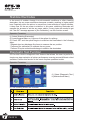
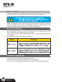
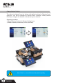
User's Manual
Version:V0.02
User’s Manual
INNO Instrument, Inc.
Table of Content
Introduction....................................................................................................................................4
Chapter l Technical Specifications.................................................................................................5
Applicable Fiber Type....................................................................................................................5
Splice Loss....................................................................................................................................5
Splice Mode...................................................................................................................................5
Heat Oven.....................................................................................................................................5
Power Supply.................................................................................................................................6
Dimensions and Weight.................................................................................................................6
Environment...................................................................................................................................6
Other..............................................................................................................................................6
Warnings For Batteries......................................................................................................6
Chapter 2 Installation.....................................................................................................................7
Safety Warnings and Cautions......................................................................................................7
Safety Warnings............................................................................................................................7
Maintenance and External Care Precautions.................................................................................8
Transport and Storage Precautions...............................................................................................8
Installation.....................................................................................................................................8
Unpacking the Splicer...................................................................................................................8
Splicer Description and Functions.................................................................................................9
Power Supply...............................................................................................................................10
AC adapter..................................................................................................................................10
Chapter 3 Basic Operation...........................................................................................................11
How to Install Cleaving Table.......................................................................................................11
Turning splicer "ON"....................................................................................................................12
Adjust the Angle of Monitor.........................................................................................................12
Adjust the LCD Monitor Brightness.............................................................................................13
Preparing the Fibers...................................................................................................................13
PAGE 01
User’s Manual
INNO Instrument, Inc.
How to Make a Splice...................................................................................................................14
Setting Fiber in the Fiber Holder...................................................................................................14
Inspecting the Fibers....................................................................................................................14
Splice...........................................................................................................................................15
How to Protect the Splicing point..................................................................................................15
Heating Procedure.......................................................................................................................15
Chapter 4 Splice Programs..........................................................................................................17
Displaying the Active Splice Program...........................................................................................17
Selecting a Splicer Program.........................................................................................................18
General Splicing Steps................................................................................................................19
Prefusion......................................................................................................................................19
Fusion.........................................................................................................................................19
Splicing Process..........................................................................................................................19
Standard Mode............................................................................................................................20
Chapter 5 Splice Option...............................................................................................................21
Setting Parameters.....................................................................................................................21
Chapter 6 Heater Mode................................................................................................................22
Selecting Heater Mode.................................................................................................................22
Editing Heater Mode....................................................................................................................23
Erasing a Heater Mode...............................................................................................................24
Heater Mode Parameters.............................................................................................................24
Chapter 7 Maintenance Menu......................................................................................................25
Replace Electrodes.....................................................................................................................25
Replacement Procedure..............................................................................................................25
Stabilize Electrodes....................................................................................................................26
Operation Procedure...................................................................................................................26
Diagnostic Test Function..............................................................................................................26
Operation Procedure...................................................................................................................26
PAGE 02
User’s Manual
INNO Instrument, Inc.
Dust Check..................................................................................................................................27
Operation Procedure....................................................................................................................27
Motor Calibration..........................................................................................................................27
Operation Procedure....................................................................................................................27
Arc Calibration.............................................................................................................................27
Operation Procedure....................................................................................................................28
Electrode Setting..........................................................................................................................28
Software Upgrading.....................................................................................................................28
Chapter 8 Other Function & Utilities.............................................................................................29
Data Storage...............................................................................................................................29
Display Splice Record..................................................................................................................29
Clearing Splicing Results in Memory............................................................................................29
Cancel Data Storage....................................................................................................................29
System Setting.............................................................................................................................29
Change Monitor Position..............................................................................................................30
Power Save..................................................................................................................................31
System information......................................................................................................................31
Appendix Ⅰ .................................................................................................................................32
Appendix Ⅱ .................................................................................................................................33
Appendix Ⅲ .................................................................................................................................35
PAGE 03
User’s Manual
INNO Instrument, Inc.
Introduction
Thanks for choosing IFS-18 High precision fusion splicer from INNO. The IFS-18
with innovative design and exquisite manufacturing technology bring customers
unprecedented splicing experience.
New technology greatly reduce splicing and heating time. Advanced estimate
method and core alignment technique ensure the accuracy of splice loss
estimation.
Its small size, compact design and reliable protection shell make it suitable for any
operating environment. Dynamic operation interface and automatic splice mode
give the customers great convenience.
For more information on IFS-18, please visit our web
www.innoinstrument.com
Model: FH-18
Universal Fiber Holder specialized for factory
This manual explains the features, specifications, operation, maintenance and
warnings about IFS-18. The primary goal of this manual is to make the user be
familiar with the splicer as soon as possible.
Important!
INNO Instrument recommends all users to read this manual carefully before
operating IFS-18.
PAGE 04
User’s Manual
INNO Instrument, Inc.
Chapter 1-Technical Specifications
Applicable Fiber Type
* SM(ITU-TG.G652) l MM(ITU-TG.651)/DS(ITU-TG.653)/NZDS(ITU-TG.655)/
ITU-TG.657/HP980/HI1060/HI1060FLEX/SM0.08mm
* Fiber count: Single
* Applicable fibers:
0.08mm/0.125mm/0.25mm/0.9mm
* Applicable fiber diameter: Cladding diameter: 80-150μm, Coating diameter:
100-1000μm
Splice Loss
Measured by cut-back method relevant to ITU-T standard
* SM: 0.02dB
* MM: 0.01dB
* DS: 0.04dB
* NZDS: 0.04dB
* G.657: 0.02dB
Splice Mode
* Preset 42 splice modes
* Internal splice data storage: 2000
* Splicing time: SM FAST mode: 7s
Heat Oven
* Applicable protection sleeve:
20mm, 30mm, 40mm, 50mm, 60mm
* Heating time: 20-900s
* Cooling time: 0- 180s
* Typical heating time: 35s
* Heater mode: 32 heat modes, preset 5 heat modes
* Heat oven: IFS-18 Special Heat Oven
PAGE 05
User’s Manual
INNO Instrument, Inc.
Power Supply
* Input power: AC 100-240V, 50-60HZ.
* Li-ion battery input: DC 9~14V.
Dimensions and Weight
* Size: Length x Width x Height = 160mm x 145mm x 148mm
* Weight: 2.15 kg (AC adapter included) 1.9kg
Environment
* Operating condition: 0-5000m above sea level, 0-95% relative humidity,
-10-50℃ . 15m/s wind.
* Storage condition: 0-95% relative humidity, -40-80℃ ; Battery: -20-30℃ for
long time storage.
Other
* Viewing Method: two camera and 5.0 inch color LCD monitor.
* 300x magnification for single X or Y view, or 180x for both X and Y view.
* Mechanical proof test: 1.96- 2.25 N.
* Terminals: USB2.0 for upgrading.
Warnings For Batteries
1) Never strike batteries with any sharp edge parts.
2) Never transport or store batteries together with the metal content.
3) Never throw, drop, impact or bend battery body. Never knock the battery with the
hammer nor thread on it.
4) Never short-circuit the battery by connecting the positive and the negative terminal
with metal content like wires.
5) Never make the positive or negative terminals in touch with the aluminum backing of
polymer-aluminum packaging material, it will make the battery short circuit.
6) Do not disassemble the battery Cells in any event.
7) Never dip battery into the water or seawater, the cells should be keep from moisture.
8) Never use or leave the battery near a heat source as fire or heater.
9) Never apply direct heat to the battery or put it into the water.
10) Never directly solder the battery.
11) Never charge batteries near the fire or in a hot environment.
12) Never put batteries into the microwave oven or any high pressure vessel.
13) Avoid long-term use of the battery or leave it at high temperature (for example, in
the strong sunlight or inside your car in extreme temperatures), otherwise it will cause
the battery be overheated, on fire, function decline or its service life be decreased.
14) Never use the damaged battery. The battery which electrolyte was leaked or
there's a smell of electrolyte should be far away from fires to avoid the battery on fire or
explode.
15) In case the electrolyte was leaked and came into contact with the skin or any other
parts of the body, rinse immediately with clear water. If the electrolyte come into contact
with the eyes, see a doctor nearby after rinsing with clear water.
PAGE 06
User’s Manual
INNO Instrument, Inc.
Chapter 2 - Installation
Safety Warnings and Cautions
As IFS-18 is designed for fusion splicing silica glass optical fibers, it is very important
that the splicer should not be used for any other purpose. The splicer is a precision
instrument and must be handled with caution. Therefore, you must follow all safety
rules and general precautions in this manual. Any behavior that not follow the warnings
and cautions will break the safety standard about the fusion splicer and may result in
electric shock, fire, and/or serious injury. INNO will not take the responsibility for those
results caused by misuse!
Safety Warnings
① Never operate the splicer in an environment where flammable liquids or vapors exist.
② Do not touch the electrodes when the splicer is on and power is supplied to the unit. The electrodes
generate high voltage and high temperatures that may cause a severe shock or bum.
③ Do not disassemble or modify the splicer, AC adapter, battery or battery charger. In particular,
do not remove or bypass any electrical or mechanical device (e.g. a fuse or safety switch)
incorporated into the design and manufacture of this equipment. The equipment must be
repaired or adjusted by an authorized technician or engineer. Unauthorized repair may result in
fire or electric shock.
④ Properly connect the AC power cord to the splicer(inlet) and wall socket (outlet). When inserting
the AC plug, make sure there is no dust or dirt on the terminals. Engage by pressing the female
plug into the splicer (inlet) and the male plug into the wall socket (outlet) until both plugs are fully
seated. Incomplete engagement may cause fuming, electric shock, or equipment damage and
may result in injury, death, or fire.
⑤ Never operate the splicer in an environment where flammable liquids or vapors exist. Risk of
dangerous fire or explosion could result from the splicer's electrical arc in such an environment.
Do not operate splicer near hot objects, in high temperature environments, in dusty/humid
atmospheres, or when water-condensation is present on the splicer. This may result in electric
shock, splicer malfunction, or poor splicing performance.
⑥ Safety glasses should always be worn during fiber preparation and splicing operation. Fiber
fragments can be extremely dangerous if they come into contact with the eye, skin, or are
ingested.
⑦ Disconnect the AC power cord from the AC adapter inlet or the wall socket (outlet) immediately
if user observes the following or if the splicer receives the following faults:
- Fumes, bad smell, noise, or over-heating occurs.
- Liquid or foreign matter falls into cabinet.
- Splicer is damaged or dropped.
If any of these faults occurs, ask our service centre for repair. Leaving the splicer in a damaged
state may cause equipment failure, electric shock, or fire and may result in injury or death.
⑧ Do not use compressed gas or canned air to clean the splicer. They may contain flammable
materials that could ignite during the electrical discharge
⑨ Use only the AC adapter designed for this splicer. Using an improper AC power source may
cause fuming, electric shock, or equipment damage and may result in injury, death, or fire.
Proper AC power source is AC 100~240v, 50~60Hz. Check the AC power source before use.
⑩ Use the supplied AC power cord. Do not place heavy objects on the AC power cord. Keep the
power cord away from heat source. Use of an improper cord or a damaged cord may cause
fuming, electric shock, or equipment damage and may result in injury, death, or fire.
PAGE 07
User’s Manual
INNO Instrument, Inc.
Maintenance and External Care Precautions
① Always avoid using hard objects to clean V-grooves and electrodes.
② Do not use any chemical other than pure alcohol (99% or greater) to clean the
objective lens, V-groove, LEDs, LCD monitor, etc., of the splicer.
③ Use a dry cloth to remove dust and dirt from the splicer.
④ If the outside of the splicer is dirty, plunge a soft cloth into diluted neutral
washing up liquid, wring out the cloth and clean. Dry the splicer with a dry cloth
but DO NOT use furniture polish or other cleaning agent.
⑤ Always follow the maintenance instructions in this manual.
Transport and Storage Precautions
① When the splicer is moved from cold to warm environment, you should allow the
splicer to warm up gradually. Otherwise, the condensation generated inside will be
harmful for the splicer.
② Pack the fusion splicer for long time storage.
③ Keep the splicer clean and dry.
④ The fusion splicer is precision adjusted and aligned. Always keep the slicer in
its carrying case to protect from damage and dirt. Put cushion package outside the
carry case for long distance transporting.
⑤ Always avoid leaving the splicer in direct sunlight or expose to excessive heat.
⑥ Do not store the splicer in dusty/humid atmospheres. This may result in electric
shock, splicer malfunction, or poor splicing.
⑦ Keep the humidity to a minimum level where the splicer is stored. The humidity
must not exceed 95%.
Installation
Important!
Please carefully follow the instructions below.
Unpacking the Splicer
Check the belt and hooks for damage before taking the splicer out.
Lift the splicer by the lifting belt as show below:
PAGE 08
User’s Manual
INNO Instrument, Inc.
Splicer Description and Functions
Operating button
Power ON/OFF
Heat oven
Lifting belt
Monitor
AC adapter
USB port
Serial port
AC adapter interface
PAGE 09
User’s Manual
INNO Instrument, Inc.
Power supply
AC adapter
1. Installation diagram is shown as follow.
Power off the splicer.
Press the release button
and take out the AC adapter.
Inserting the AC adapter into the
power unit dock until you hear "click".
Release button
Take out AC adapter
2. The connection diagram is shown as follow.
PAGE 10
User’s Manual
INNO Instrument, Inc.
Chapter 3 - Basic Operation
How to Install Cleaving Table
Fix the cleaver on the Cleaving Table by matching screw.
PAGE 11
User’s Manual
INNO Instrument, Inc.
Turning Splicer "ON"
Press "POWER" button on the operation panel. The ready screen is displayer after
the motors rest to their initial positions.
Adjust the Angle of LCD Monitor
Adjust the monitor angle to comfortably watch the screen.
PAGE 12
User’s Manual
INNO Instrument, Inc.
Adjust the Monitor Brightness
In the initial interface, press "←" or "→" to change the monitor brightness until it is
clear enough.
Preparing the Fibers
3 steps for preparing fibers:
Step 1: Strip the fiber
① Remove at least 50mm of secondary
coating (valid for both tight and loose tube
secondary coating) with an appropriate stripper.
② Remove approximately 30mm of primary
coating with an appropriate stripper.
Step 2: Clean the fiber
Clean the bare fiber thoroughly with alcohol
impregnated gauze or lint-free tissue.
Step 3: Cleave the fiber
Cleave the fiber by high precision fiber cleaver.
In order to get excellent splice result, high
precision fiber cleaver should be used, such as
INNO VF- fiber cleaver. And the cleave length
also should be precisely controlled (shown
below).
Important!
From this point, you must be very careful
with the fibers to ensure that they do not
become dirty again.
- avoid putting them down on a dusty
working surface
- avoid waving them around in the air.
- check if the V-grooves are clean, if not,
wipe them clean
- check if the fiber clamps are clean, if
not, wipe them clean
PAGE 13
User’s Manual
INNO Instrument, Inc.
How to Make a Splice
Setting Fiber in the Fiber Holder
① Open the wind shield.
② Raise the fiber clamps.
③ Place the fibers into V-grooves.
④ Make sure the fiber ends are visible on the monitor.
(4a) If the fiber ends are not visible, the splicer will try to find them by moving
the fibers horizontally. The ends will be found if the fibers are placed within the
mechanical movement range of the horizontal motors.
(4b) If not, an error message will be displayed. The splicer will not find fiber ends
that are placed above or below the imaging area.
(4c) Normally, this should only happen if the V-grooves or the fibers are dirty, or if
the splicer is not well adjusted.
⑤ Clamp the fiber in position by lowering both sets of fiber clamps.
⑥ Close the safety shield.
Inspecting the Fibers
Make sure the fibers are clear and be well cleaved before you proceeding the
splice.
If you find any defects as illustrated above, remove the fibers and prepare again.
PAGE 14
User’s Manual
INNO Instrument, Inc.
Note: The fibers are checked
automatically when you press "Set"
button. The splicer automatically
focuses the fibers and checks for
damage or dust particles.
Splice
① Select the appropriate splicing mode.
② Press "SET" to start splicing.
How to Protect the Splice
After splicing, protect the joint by using a heat-shrink sleeve and the heat oven
which is mounted onto the splicer.
Heating Procedure
① Open the heat oven lid.
② Lift the left and right fiber clamps on the splicer.
Holding the heat-shrink tube (previously placed onto the fiber), lift the spliced fibers
and holding them taut, move the heat-shrink tube so that it is centered over the
splice point.
③ Move both the fibers and the heat-shrink tube over to the heat oven and place
them in the oven clamps.
④ Press "HEAT" to start. After heating, the led indicator will go out with buzzing.
PAGE 15
User’s Manual
INNO Instrument, Inc.
Opening the heater lid
Splice
Moving the fibers and protection
sleeve to the heat oven.
Heating Indicator
PAGE 16
Heat Button
User’s Manual
INNO Instrument, Inc.
Chapter 4 - Splice Programs
IFS-18 has an intuitive and simple, but very powerful program structure. Splice
programs define arc currents, splice times as well as various parameters used
when performing a splice. Therefore, it is essential to select the correct splice
program in accordance with the type of fiber you want to splice.
There are a number of "pre-defined" splice programs for common fiber
combinations (see below). However, it is also easy to either modify or write
new splice programs to further optimize the parameters for more unusual fiber
combinations. (These are known as "user-defined" programs.)
Displaying the Active Splice Program
The active splice program is always displayed at the top of the screen (see below).
The splicer uses this program when you press “confirm” in Main menu:
Displaying the Active Splice Program
PAGE 17
User’s Manual
INNO Instrument, Inc.
选择熔接模式
① Select "Splice Mode"
from the "Main menu".
② Select appropriate
splice program.
③ Select the splice mode
you want.
④ Press "RESET" return
to the initial interface to
check the selected splice
program.
PAGE 18
User’s Manual
INNO Instrument, Inc.
General Splicing Steps
This section explains the steps involved in automatic splicing process and
describes how various program parameters are related to this process. The normal
splicing process can be divided into two sections; prefusion and fusion.
Prefusion
During prefusion, the splicer performs automatic alignment and focusing, where
the fibers are subjected to a low prefuse current for cleaning purposes; a prefuse
image is also taken. At this point, the user is informed of any problems recognized
in the prefuse image, such as a poorly prepared fiber. The splicer will then issue a
warning before the fibers are fused together.
Fusion
During fusion, the fibers are joined together and subjected to five different currents
as illustrated below. An important parameter, which changes during splicing, is
the distance between the fibers. During Pre-fusion, the fibers are apart. With the
current phase changing, fibers are splicing gradually.
Splicing Process
Arc power and Arc time are considered the two most vital parameters. How those
parameters affect the splicing process will be described in next section "Splice
option".
Below is a figure showing the arc discharge conditions (relationship between
"Arc power" and "Motor motion"). These conditions can be edited by changing
the splicing parameters listed below. Depending on the splice mode, certain
parameters cannot be changed.
PAGE 19
User’s Manual
INNO Instrument, Inc.
Standard Mode
PAGE 20
User’s Manual
INNO Instrument, Inc.
Chapter 5 - Splice Option
Setting Parameters
① Select [Splice Option] in "main menu".
② Click your item and change the parameter.
PAGE 21
User’s Manual
INNO Instrument, Inc.
Chapter 6 - Heater Mode
There are 32 heating modes and preset 5 heating modes by INNO factory. The
others could be defined by users. Select the one best suited for the protection
sleeve used.
For each type of protection sleeve, IFS-18 has its optimum heating mode. These
modes can be found in the database area for reference. Copy the appropriate
mode and paste it to the user-programmable area. The operator can edit the userprogrammable modes.
Selecting Heater Mode
Select "Splice mode" and then enter the "Heating mode" menu.
① Select [Heating Mode]
menu from "main menu".
② Select [Select Heater
Mode] menu.
PAGE 22
User’s Manual
INNO Instrument, Inc.
③ Select the heater mode.
④ Press "RESET" to return
to the initial interface to check
the heater mode selected.
Editing Heater Mode
Tube-heating conditions stored in heater mode can be edited or changed.
(1) Select [Edit Heater
Mode] through [Heater
Mode] menu.
(2) Select the mode to
be edited.
PAGE 23
User’s Manual
INNO Instrument, Inc.
(3) Select the parameter to
be changed, and edit it.
Erasing a Heater Mode
① Enter [Heating Mode] menu.
② Select [Delete Heater Mode].
③ Select the heater mode to
delete.
Note: The mode shown in gray (20mm, 30mm) is the system
default initial mode and could not be delete.
PAGE 24
User’s Manual
INNO Instrument, Inc.
Chapter 7 - Maintenance Menu
The splicer has a function to perform routine maintenance. This section describes
how to use the maintenance menu.
(1) Press "menu" button, select [maintenance menu].
(2) Select a function to perform.
Replace Electrodes
During arc process, the oxide generated on the tips of electrodes. It is
recommended that the electrodes should be replaced after 3,500 arc discharges.
When the number of arc discharges reaches a count of 3,500, a message
prompting to replace the electrodes is displayed immediately after turning on the
power. Using the electrodes without a replacement will result in greater splice loss
and reduced splice strength.
Replacement Procedure
(1) Execute [Replace Electrodes] in [Maintenance Menu].
(2) Instruction messages will appear on the screen to turn off the power, then power
off.
(3) Remove the old electrodes.
(i) Loosen screw located on electrode cover.
(ii) Take electrode out of electrode cover. (Electrode fits into electrode cover)
Loosen the screw
Remove old
electrode and
install new one
(4) Clean the new electrodes with alcohol-impregnated clean gauze or lint-free
tissue and install them in the splicer.
(i) Insert the electrode in the electrode cover.
(ii) Place the electrode cover on the splicer and tighten screw.
(5) INNO recommends all operators to do stabilizing electrodes and arc calibration
after electrodes replacing to keep good splice results and splice strength. (Details
will be described below. )
PAGE 25
User’s Manual
INNO Instrument, Inc.
Stabilize Electrodes
In the event of sudden change in environmental conditions or after cleaning
electrodes, the arc power sometimes becomes unstable, resulting in higher splice
loss. Especially when the splicer is moved from lower altitudes to higher altitudes,
it takes time for the arc power to stabilize. In this case, stabilizing electrodes will
expedite the process to set the arc power stable. If many tests are needed to get
the “Test OK” message appears in [Arc Calibration], use this function as well.
Operation Procedure
(1) Select [Stabilize Electrodes].
(2) Load prepared fibers on V-groove of the splicer for splicing.
(3) Press SET and the splicer begins to stabilize the electrodes in the following
ways:
* Repeats short arc discharge five times to measure the arc position.
* Performs [Arc calibration] to calibrate the arc power.
* Perform 20-cycle continuous discharge to stabilize the electrodes.
Diagnostic Test Function
IFS-18 has a built-in diagnostic test feature that allows the user to perform a
simple one step evaluation of splicer performance covering several different critical
variables. Perform this function in the event of splicer operation trouble.
Operation Procedure
(1) Select [Diagnostic Test ]
in [Maintenance Menu].
(2) The following checks will be made.
PAGE 26
User’s Manual
INNO Instrument, Inc.
Dust Check
During normal splicing, the splicer observes fibers through image acquisition and
processing. Dust or contaminants on the cameras and lenses disturbs normal
observation of fibers and may result in improper splicing. This function checks the
optical path for the presence or absence of contaminants and judges whether they
cause trouble for fiber splicing.
Operation Procedure
(1) Select [Dust Check] in [Maintenance Menu].
(2) If fibers are set in the splicer, remove them and press "SET" button to start the
dust check.
(3) If contamination is discovered during the process, the message "Find dust on
the camera lens" will be displayed on the screen. Press back button two times, the
location of contamination will shown on the screen. Clean the objective lenses and
redo [Dust Check] until the message "Operation Completed" is displayed.
Note: If contamination still exists after cleaning the objective
lenses, please contact with the agent.
Motor Calibration
Motors are adjusted at the factory before shipping. However, settings can be changed
in various reasons. This function automatically calibrates the speed of all 6 motors.
Operation Procedure
(1) Select [Motor Calibration] in [Maintenance Menu].
(2) Load prepared fibers in the splicer and press SET button.
(3) Speeds for all motors are automatically calibrated. The message "Operation
Completed" will be displayed if the operation is completed.
Arc Calibration
Atmospheric conditions such as temperature, humidity, and pressure are constantly
changing, which creates variability in the arc temperature. This splicer is equipped with
temperature and pressure sensors that are used in a constant feedback monitoring
control system to regulate the arc power at a constant level.
However, changes in arc power due to electrode wear and glass adhesion cannot be
corrected automatically. Also, the center position of arc discharge sometimes shifts to
the left or to the right. In this case, the fiber splicing position has to be shifted in relation
to the arc discharge center. It is necessary to perform an arc power calibration to
eliminate those problems.
PAGE 27
User’s Manual
INNO Instrument, Inc.
Operation Procedure
(1) Select [Arc Calibration] in [Maintenance Menu] to display Arc Calibration on the screen.
(2) Set prepared fibers on the splicer and press SET to execute arc calibration.
(3) After arc calibration, there are two values show on the screen. If the right value achieves
11±2, the message "Test Finished " will be display. Otherwise, multiple iterations of arc
calibration are needed until the message "Test Finished" is displayed.
Electrode Setting
Set the electrode change warnings. INNO recommends that replace the electrodes
every 3,500 discharge to keep perfect splice results.
(1) Select [Electrode Setting] in [Maintenance Menu] to display Setting Electrodes
on the screen.
(2) Set Electrode Caution and Electrode Warning.
Software Upgrading
① Select [Update Software] in [Maintenance Menu].
② Connect the driver contains upgrading files to the USB port.
③ Press OK to upgrading automatically. The splicer will restart after upgrading.
PAGE 28
User’s Manual
INNO Instrument, Inc.
Chapter 8 - Other Functions & Utilities
Data Storage
This splicer stores up to 2,000 splicing results. Contents of data stored are different
depending on splicing mode.
Display Splice Record
Splicing results stored in the memory can be displayed.
Select [Data Storage] Menu, then select [Display Splice Record] to check the
records.
Clearing Splicing Results in Memory
Splicing results can be cleared by part or whole.
(1) Select [Clear Splice Memory] and Input specific number (begin-number and
end-number) of splicing results to be cleared.
(2) Select [Clear Splice Record] to execute clearing.
Cancel Data Storage
If you don’t want to store the records, select <ON> in the [Cancel data storage] Menu.
System Setting
This menu is used to change system parameters and set user authority.
PAGE 29
User’s Manual
INNO Instrument, Inc.
Change Monitor Position
The splicer is shipped from the factory with default setting for "Monitor Front"
operation. This can be changed to "Monitor Rear" operation. When [Monitor
Position] is changed, the direction of the arrow keys is reversed.
Operating procedure:
① Select [Monitor Position] in [System Setting] menu.
② Select a monitor position as you like (front/rear).
Note: Press "↑ ↓" to swift the monitor position quickly.
PAGE 30
User’s Manual
INNO Instrument, Inc.
Power Save
This function is important for battery conservation. If the power saving function is
not set during battery pack use, the number of splicer cycles will be reduced.
(1) Insert a power unit and turn splicer power on.
(2) Select [Power Save Option] in the [System Setting]. [Power Save Option] is
displayed for the type of power supply used.
(3) Change value of [Monitor Shut Down] AND [Splice Shut Down].
System Information
Select [System Information], the following information is displayed.
PAGE 31
User’s Manual
INNO Instrument, Inc.
Appendix I
Splice loss increase: Reason and solution.
PAGE 32
User’s Manual
INNO Instrument, Inc.
Appendix II
During the splice operating process, if the error messages is shown on the screen.
Follow the solution precisely as shown in the list below. If it is not possible to
eliminate the problem, the splicer may require service by a qualified service center.
Please contact with sale agent.
PAGE 33
User’s Manual
INNO Instrument, Inc.
PAGE 34
User’s Manual
INNO Instrument, Inc.
Appendix III
Questions and Troubleshooting
1. Power does not turn off when pressing NO/OFF button.
★ Press and hold the key until the LED color changes from green to red.
2. Few splices can be made with a fully charged battery pack
★ If the power saving function is not enabled, battery power degrades quicker.
★ Always enable it to conserve power usage.
★ If degradation appears (memory effect), or if the battery pack is stored for an
extended period of time, completely discharge it. After discharge completion,
recharge the battery pack.
★ The battery pack has reached the end of its service life. Install a new battery
pack.
★ The battery pack uses chemical reaction. The capacity decreases at low
temperature,especially at lower than 0 degree C.
3. Error message appears on monitor
★ Please refer to appendix II.
4.Inconsistent splice loss / High splice loss
★ Clean the V-grooves, fiber clamps, wind protector mirrors, and objective lenses.
★ Replace the electrodes.
★ Please refer to Appendix I.
★ The splice loss varies according to the cleave angle, arc conditions and fiber
cleanliness.
5. Monitor suddenly turned off
★ The monitor will turn off after an extended period of splicer inactivity, if the power
saving function is enabled. Press any key to return to the normal state.
6. Splicer power suddenly turned off without “Low Battery” message
★ The monitor will turn off after an extended period of splicer inactivity, if the power
saving function is enabled. Press any key to return to the normal state.
7. Identify fibers error in AUTO mode
★ AUTO mode is applicable for SM, MM, NZ fiber. Errors may occurs while splicing
special fibers.
8. Mismatch between Estimated splice loss and Actual splice loss
The estimated loss is a calculated loss, so it can be used for reference only.
The optical components of the splicer may need to be cleaned.
9. Fiber protection sleeve does not shrink completely.
Extend the heating time.
10. Method to cancel heating process.
Press Heat key to stop during heating process. The LED light will go off after
pressing.
PAGE 35
User’s Manual
INNO Instrument, Inc.
11. Fiber protection sleeve adhered to heating plate after shrinking
Use a cotton swab or a similar soft tip object to push and remove the sleeve.
12. Forgot password
Please contact the sale agent.
13. No arc power change after [Arc Calibration]
The displayed arc power in each splice mode does not change.
14. Forgot to load fibers while execute some specified function that fibers are
needed.
splicer, and press SET to continue or press RESET.
15. Upgrading failure
When users use the "new" U-disk to upgrade, the splice may not be able to
splicer.
If you cannot solve the problems, please contact the sale agent.
16. Other
Please refer to the video in user's CD.
Manufacturer:
INNO INSTRUMENT, INC.
Address: 65-3, Sangdaewondong, Jungwongu, Sungnamsi,
Kyeonggido 462-807, Republic of Korea.
Tel: +82 31 742-8755
www.innoinstrument.com
China Branch:
INNO INSTRUMENT(SHANGHAI) INC.
Address: 6F Building 39, No.333 Qinjiang Road, Xuhui
District, Shanghai, China.
Tel: +86 21 6405-6995
www.innoinstrument.com
INNO IFS-18 Exclusive agent in mainland China:
SHENZHEN EASTSEA PHOTOELECTRIC TECHNOLOGY CO., LTD.
Address: 11B, HongSong Building A, TaiRan 9 Road, Futian
District, Shenzhen, Guangdong Province, China.
Tel: +86 755 8860-8360
www.eastseachina.com
PAGE 36
The End
* Design is subject to change without prior notice.