1
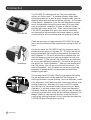
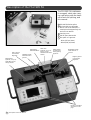
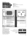
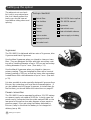
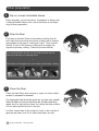
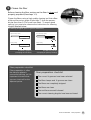
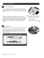
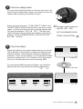
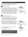
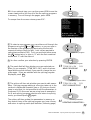
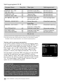
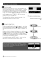
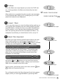
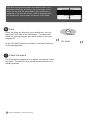
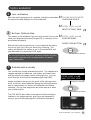
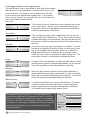
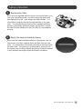
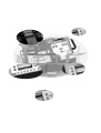
User’s manual for the FSU 995 FA
single fiber fusion splicer by Ericsson
1
2
Table of contents
Introduction ..................................................................................................................... 4
Safety Information ........................................................................................................... 5
Description of the FSU 995 FA ........................................................................................ 6
Setting up the splicer ...................................................................................................... 8
BASIC OPERATION ......................................................................................................... 9
Splicing quick guide ........................................................................................... 9
Fiber preparation .............................................................................................. 10
Splicer preparation ........................................................................................... 12
Splicing mode and program selection .............................................................. 14
Automode splicing............................................................................................ 17
Manual mode splicing ...................................................................................... 18
Splice evaluation .............................................................................................. 21
Splice protection .............................................................................................. 23
ADVANCED OPERATION .............................................................................................. 25
Fusion program structure ................................................................................. 25
Overview .......................................................................................... 25
Program name ................................................................................. 26
Fiber type......................................................................................... 26
Splicing process .............................................................................. 28
Program parameters ........................................................................ 36
Pre-defined programs: Programs 01 - 10 ......................................................... 41
Program editing: Programs 11 - 50 ................................................................... 43
Parameter editing review ................................................................................. 53
Special functions.............................................................................................. 55
Advanced splicing parameters ........................................................ 55
Service functions: #-button ............................................................. 57
Advanced hot image analysis ......................................................... 60
Quick character selection ............................................................... 61
Global parameters: Program 00 ...................................................... 61
Upload / Download Software ........................................................................................ 65
Maintenance ................................................................................................................. 66
Power connection ............................................................................................ 66
Fiber clamps and V-grooves ............................................................................. 67
Electrodes ........................................................................................................ 68
Mirror one ......................................................................................................... 70
Maintenance time table ................................................................................... 70
Appendices
A-Troubleshooting ............................................................................................ 71
B-Technical Data .............................................................................................. 74
C-Parameter and program editing flow charts ................................................. 75
Index ............................................................................................................................. 80
Ericsson representatives ............................................................................................... 82
Table of contents
3
Introduction
FSU 995 FA
The FSU 995 FA is designed to be “the only single fiber
splicer you’ll ever need. ” It handles all basic single fiber
splicing procedures, as well as more complex tasks such as
tapering, attenuator making and erbium splicing. At the heart
of the splicer’s operations is the hot core alignment process,
which individualizes the splicing procedure to fit your fiber
type and climactic conditions in order to offer the lowest
possible splice loss every time. Then, just to make sure, the
FSU 995 FA estimates this splice loss with an extremely
accurate splice loss estimation technique based on mode
coupling theory (micro-bending) and hot image processing.
There are two ways of categorizing the FSU 995 FA’s operations, and this manual will be organized according to both of
them:
Operations
Processes
4
Introduction
On the one hand, the FSU 995 FA splicing programs can be
divided into two groups: Programs 01 - 10, which are the ten
splicing programs that come pre-defined with the machine,
and Programs 11 - 50 which are the forty editable slots you
have for designing your own splicing programs to suit your
special needs. In this manual, the instructions you will need
to run the pre-defined programs (01 - 10) will be the focus of
the section on “Basic Operation.” After you are familiar with
the FSU basics, you can go on to the second section, “Advanced Operation,” which outlines the structure of splicing
programs in greater detail, and describes the method for
designing your own.
On the other hand, FSU 995 FA splicing programs (including
the pre-defined ones) can be organized according to six
splicing processes: normal splicing, hot core alignment, small
core alignment, mode field matching, attenuator making, and
pulling or tapering. Whereas, this cross-cut of FSU operations will be only mentioned briefly in the section on “Basic
Operation”, it will play a large role in “Advanced Operation.”
Generally speaking, even though you will not need to specify
splicing processes when using the pre-defined programs, it is
always helpful to keep splicing process in mind when discussing any splicing program, since it specifies the steps the
FSU 995 FA goes through when splicing.
Safety Information
Operational Precautions
Maintenance Precautions
Transport and Storage
l Do not use the splicer
in locations where there
is a risk of explosion.
l Never touch the electrodes when the splicer
is on.
l Never use hard objects to clean the Vgrooves or electrodes.
Use the supplied brush,
or in the case of the Vgrooves, isopropyl alcohol and cotton swabs.
l Never leave your
splicer in direct sunlight
or in places where it
might be exposed to
excessive heat (such as
in vehicles parked in the
sun).
l Never open the safety
shield or the power supply during operation.
l Never use acetone for
cleaning any part of the
splicer.
l Never loosen any
screws except those
mentioned in this
manual, since you
may harm important
adjustments.
l Never use cans with
compressed gas to clean
any part of the splicer.
l Do not insert objects
other than stripped and
cleaned optical fiber or
cleaning and maintenance tools into the
splicer.
!
l Keep the electrode
housing clean and dry at
all times.
l Use the electrode
cleaning program after
every time you clean or
change the electrodes,
otherwise the arc will be
unstable.
l Always transport the
splicer in its carrying
case to avoid damage to
its precision parts.
l Keep the humidity to a
minimum where the
splicer is stored. The
humidity must not exceed 95%.
l If moisture forms on
the optics when moving
the splicer from an area
with very cold temperature to a warmer environment, let the splicer sit
and warm up before
using it.
l Close the safety shield
during transport.
General rule is...
The FSU 995 FA is a precision instrument, and must be treated as such.
Safety Information
5
Description of the FSU 995 FA
The FSU 995 FA is delivered
in a rugged, cabin-size carrying case along with the basic
set of tools for splicing, and
this manual.
3
1
1
2
2
3
4
5
5
Left V-groove
Used in fiber
alignment.
4
Heat oven
Electrodes/
(optional, see p. 23)
Electrode block
Plug-in unit for
standard heat-shrink
sleeves.
Left fiber clamp
Fixes fiber into Vgrooves.
Fiber fixture
(optional, see p. 23)
Holds fiber secure
during removal.
FSU 995 FA fusion splicer
Tool set with one electrode
brush, one set of tweezers, a
seven piece hexagonal key set,
and one hex wrench
Carrying case
Pair of spare electrodes
Two pairs of V-grooves
-Blue (125 mm/1mm)
-Black (250 mm/2mm)
Safety shield
For protection
during splicing
sequence.
Right fiber clamp
Fixes fiber into Vgrooves.
Right V-groove
Used in fiber
alignment.
Monitor and buttons
described on next
page.
6
Description of the FSU 995 FA
Rear panel
1
2
3
1
2
4
3
5
4
6
6
6A Fuse
Output for video
Auxiliary 12V video output (see Appendix B)
2A Fuse
12V power input
RS 232 (see Appendix B)
5
Buttons
FSU 995 FA
On
Off
Right
Left
Esc
+
*
Focus
Mode
_
Hot
Image
View
Up
Down
Enter
0-9
0-9
0-9
Fuse
Select
#
Gap
Left arrows
Mode
Hot Image
To turn splicer on and off.
To abort operations and to access
parameters.
To change splice mode
To flip through hot images.
Programming buttons
No
Yes
No
Enter
0-9
0-9
0-9
To answer “yes” to programming questions.
To answer “no” to programming questions.
To enter one’s selections.
To choose first numerical place.*
To choose second numerical place.*
To choose third numerical place.*
Up arrow
Down arrow
For axial fiber alignment.
For axial fiber alignment.
Gap
To set a fine gap or close a gap.
Fuse
To initiate a splicing procedure.
Select/#
To check battery and to access
service parameters.
Monitor
Controls
Yes
+
View
To adjust focus.
To adjust focus.
To change content of monitor.
On/Off
Esc/c
To move left fiber along its own
axis (e.g. toward right fiber).
Right arrows To move right fiber along its own
axis (e.g. away from left fiber).
* For example, to get the number ‘147’, you would press the first button once, the second button 4 times, and the third 7 times.
Monitor
The FSU 995 FA monitor is organized into a viewing area that allows
you to see the fibers from two
different angles, and a text area
that is itself divided into two text
fields: a mode field and a message
field. The mode field informs you
which mode and programs you are
working with. The message field
poses questions, gives instructions
and tells you what it is doing.
Fibers from 1st angle
If you press VIEW, you then see the
fibers from the 2nd angle.
Mode field
Message field
FSU 995FA
AUTO MODE
AUTO ALIGNING/FUSION
Description of the FSU 995 FA
7
Setting up the splicer
The adjacent set-up checklist is not in any way exhaustive, but it does present the
basics you should have at
hand before sitting down and
splicing.
Set-up checklist
Optical fiber
Fiber holders
FSU 995 FA manual
V-grooves
Cleaner
Heat-shrink oven
Cleaver
Heat-shrinkable sleeves
Cotton swabs
Power supply or battery
Electrode brush
V-grooves
The FSU 995 FA is delivered with two sets of V-grooves, blue
V-grooves and black V-grooves:
Use the blue V-grooves when you intend to clamp on bare
fiber. They are designed for fiber with tight secondary coating with a cladding diameter of up to 125 mm and secondary
coating diameter of up to 1 mm. (See also p. 11).
Use the black V-grooves when you intend to clamp on
primary coating. They are designed for fiber with a nominal
primary coating of 250 mm, as well as, loose-tube secondary
coated fibers with a tube diameter of up to 2 mm. (See also
p. 11).
It is also possible to order specially designed V-grooves from
Ericsson by contacting your local service representative. If
you do indeed need to change V-grooves, or install them for
the first time, you should follow the instructions on page 67.
Power connection
The FSU 995 FA can be operated by either a 12 V DC battery
or a power supply unit rated at 50-60 Hz. In both cases the
power cord is connected into the outlet marked PWR on the
rear panel of the splicer (see also diagram of rear panel on
previous page). If you are using the battery delivered by
Ericsson, keep in mind that the battery is not charged on
delivery (see p. 66).
Setting up the splicer
3
Strippers
Isopropyl alcohol
8
FSU 995 FA fusion splicer
BASIC OPERATION - Quick guide
The following steps outline basic operation of the FSU 995 FA,
and refer to the pages where they are explained in greater detail.
1
Connect the splicer to the power supply ................. 8
2
Prepare the fibers ..................................................... 10
3
Turn on the splicer and place the fibers ................. 12
4
Select splicing mode and program ......................... 14
5
Splice the fibers ........................................................ 17
6
Check the splice ....................................................... 21
7
Protect the splice ..................................................... 23
Strip, clean and cleave the fibers.
Note: The splicer will turn off automatically when you re-open the
safety shield after splicing.
On
Off
Mod
e
Choose between the two splicing modes: Automode and Manual
mode. (Note that the splicer always starts in Automode when just
turned on). A list of the pre-defined splicing programs (01-10) is
found on page 16.
Fuse
Press the fuse button.
Check the splice visually by pressing VIEW and scrolling through
stored images. Evaluate the splice quantitaly by taking note of the
estimated splice loss.
Protect the splice with a heat-shrinkable sleeve.
BASIC OPERATION - Quick guide
9
Fiber preparation
1
Slip on a heat-shrinkable sleeve
Easily forgotten, yet so frustrating. Remember to always slip
a heat-shrinkable sleeve onto one of the fibers at the beginning of fiber preparation.
2
Strip the fiber
First remove at least 50mm of secondary coating (true for
both tight and loose tube secondary coating) with a stripper
appropriate to the type of coating you have. Then remove
around 25 mm of the primary coating with a stripper designed for primary coating. (See also pictures below).
It is important that you do not put undue stress on the
fibers by bending or crimping them.
v
Illustrations of strippers for secondary and primary coating
Loose tube secondary coating
3
Tight secondary coating
Primary coating
Clean the fiber
Clean the bare fibers with a tissue or a pair of cotton swabs
soaked in propanol or ethanol.
It is important that from this point on you are very careful
with the fibers to ensure that they do not become dirty
again (such as laying them down on a dusty working surface,
or even waving them around in the air).
It is also a good idea at this stage to check to be sure the Vgrooves are clean, and if not, wipe them down as well.
10
BASIC OPERATION - Fiber preparation
4
Cleave the fiber
Before cleaving the fiber, make sure the fiber is clean and
properly prepared (See steps 1-3).
Cleave the fibers using a high quality cleaving tool that offers
a flat end-face at an angle of less than 1o from the perpendicular (less than 0.5o for small core fiber). To ensure good
splicing, you must also observe the instructions for cleaving
lengths detailed below.
Cleaving lengths (plus V-groove selection)
Tight secondary coating
Loose secondary coating
> 12 mm
primary coating
> 17 mm
> 5 mm
Primary coating
Primary coating
> 17 mm
Use Blue V-grooves
(Clamping on bare fiber)
> 5 mm
Use Black V-grooves
(Clamping on primary coating)
Fiber preparation checklist
Fiber preparation is often
the decisive phase in
successful splicing, so it is
important to ensure that
you can check off on the
adjacent points.
Fiber preparation checklist
The correct V-grooves have been selected
The fiber clamps and V-grooves are clean
The fibers are completely stripped
The fibers are clean
The end-faces are well-cleaved
The correct cleaving lengths have been achieved
BASIC OPERATION - Fiber preparation
11
Splicer preparation
Turn on the splicer
Turn on the splicer by pressing the ON/OFF button in the
upper left-hand corner. (Remember that the splicer will turn
off automatically when you open the safety shield after splicing.)
On
Off
“
The splicer always starts in Automode, and thus will read
“FSU 995 FA AUTO MODE” in the mode field. In the message field you will get a message telling you that it is calibrating parameters. Once calibration is completed, the splicer
will tell you to “INSERT FIBERS” and to “CLOSE SAFETY
SHIELD.”
2
Insert fibers
Place the fibers into the V-grooves until they are visible in the
monitor, and then close the clamps. Make sure to avoid
sliding the fibers along the V-grooves, but rather position
them over the V-grooves and then tilt them down into place
(see picture below).
Proper (and not so proper) insertion of the fibers:
1
12
BASIC OPERATION - Splicer preparation
2
FSU 995 FA AUTO MODE
PARAMETER UPDATING...
INSERT FIBERS
“
1
CLOSE SAFETY SHIELD
3
Close the safety shield
Once you have placed the fibers so that you see them in the
monitor and closed the fiber clamps, you must also close the
safety shield by sliding it smoothly into place.
4
“
Program name Program #
(eg. SM + SM P01)
“
At this point the messages, “CLOSE SAFETY SHIELD” and
“INSERT FIBERS” will be replaced with a new series of messages. The first will inform you which splicing program was
last used (for example, “SM + SM P01”). The other messages will tell you about coming next stages in the splicing
process: “AUTO ALIGNING/FUSION” and “PRESS FUSE
BUTTON.” But first....
AUTO ALIGNING/FUSION
PRESS FUSE BUTTON
Check the fibers
Before you take any more steps toward splicing, you should
check the fibers in the monitor to make sure they are clean
and well-cleaved. (See illustrations below for examples of
problems). If you see any defects, you should take the fibers
out and re-prepare them. Don’t forget to check both views,
which you can alternatively access by pressing VIEW.
If you are having difficulty seeing the fibers, you should try
adjusting the focus by pressing the buttons + and - .
Upper view
View
Check fibers in other view
The following pictures represent fiber preparation defects
that necessitate re-preparation of the fibers.
Dust on fiber
Tang
Chip
Large cleave
angle
Lower view
BASIC OPERATION - Splicer preparation
13
Splicing mode and program selection
Though the splicer is saying in the message field to “PRESS
FUSE BUTTON,” you should make sure the correct splicing
mode and program are selected.
1
Select splicing mode
Mode
Change splicing mode
“
2
FSU 995 FA MANUAL MODE
“
As mentioned earlier, the default splicing mode is Automode,
and this will be the mode the splicer is in when you just turn it
on. In Automode, the splicer automatically carries out fiber
alignment and initiates fusion. However, if you want to manually align the fibers and initialize splicing, you can change to
Manual mode by pushing the MODE button. The mode field
will then read to “FSU 995 FA MANUAL MODE.” To change
back to Automode, just push MODE again. Remember that
you can always check which mode you are in during splicer
preparation by reading what is displayed in the mode field.
toggle between by pushing MODE
FSU 995 FA AUTO MODE
Select splicing program
In this section on Basic Operation, we are only going to use
the pre-defined programs (Programs 01-10) as examples, but
you would follow the same selection procedure if you wanted
to load in one of your own programs created through the
instructions outlined in the section on Advanced Operation.
B If you press Yes , the message field will then be open for
you to enter a new program.
Enter
To change splicing program
“
“
A The first step is to press the ENTER button. At this point
both the mode and the message field will change. The mode
field will display the current splicing program, and the message field will ask you if you want to change it. For the purposes of demonstration, we are going to assume that the
current splicing program is program 01, NORMAL SM +SM.
NORMAL SM + SM P01
NEW PROGRAM?
Yes
Confirm wish to change
If you press No , you will jump to step F.
To see a list over the pre-defined programs (Programs 0110), you can either look on page 16 of this manual, or
follow the instruction in optional step BB on the next page
as to how you can access the screen-viewer.
14
BASIC OPERATION - Splicing mode and program selection
cont., next page
BB As an optional step, you can then press VIEW to see the
sceen-viewer with a list over all of the the splicing programs
in memory. To scroll through the pages, press VIEW.
To escape from the screen-viewer, press ESC.
View
Open screen-viewer
NORMAL SM+SM
DSF SM+SM
TITAN SM+SM
NORMAL MM+MM
ECCENTRIC SM+SM
ERBIUM+SM MCVD
ERBIUM+SM OVD
SM ATTENUATOR
SM FIBER LENS
SM 80 UM MICRON
P01
P02
P03
P04
P05
P06
P07
P08
P09
P10
P11
P12
P13
P14
NORMAL SM + SM
EXIT SCREEVIEW, ESC
P01
Screen-viewer for selecting a new program
C To select a new program, you can either scroll through the
programs using the
and
buttons, or you can type in
the number of the program you want using the first two
numerical buttons (from the left). Let’s say we wanted to
splice titanium fibers (P03). To do so we would either press
the
button twice, or type in “0” with the first numerical
button and “3” with the second.
0-9
OR
0-9
Select new program
Enter
Enter new program
E The mode field will then display your new selected program (In our example, “TITAN SM + SM”), and in the message field the splicer will ask if you want to change the program again. If you are satisfied with the splicing program
displayed, press No .
“
TITAN SM + SM
P03
NEW PROGRAM?
“
D You then confirm your selection by pressing ENTER.
No
“
Confirm program choice
“
TITAN SM + SM
P03
EDIT PARAMETERS?
No
“
F The splicer will then ask whether you want to edit parameters. Splicing program editing is a function taken up in the
section on Advanced Operation (see p. 43), but you should
keep in mind that it is not possible to edit the parameters in
Programs 01-10 (the ones we are using here as examples).
So to end splicing program selection and return to splicing
mode, you should press No again.
Confirm parameters
The splicer will then update the parameters in memory so
they match those of the splicing program you have chosen,
UPDATING PARAMETERS...
and return to splicing mode (see definition, following page)To
see a list over the pre-defined programs (Programs 01-10),
you can either look on page 16 of this manual, or follow the
instruction in optional step BB on the next page as to how
you can access the screen-viewer.
BASIC OPERATION - Splicing mode and program selection 15
“
Splicing programs 01-10
Program Name
Prog. No.
NORMAL SM + SM
DSF SM + SM
TITAN SM + SM
NORMAL MM + MM
ECCENTRIC SM + SM
01
02
03
04
05
ERBIUM + SM MCVD**
06
ERBIUM + DSF OVD**
07
SM ATTENUATOR
SM FIBER LENS
SM 80 UM MICRON
08
09
10
Fiber type
Splicing process*
Standard single fiber
Depressed cladding fiber
Titanium fiber
Mulitmode fiber
Standard single fiber
with eccentric core
Erbium fiber with
single fiber
Erbium fiber with
dispersion shifted fiber
Standard single fiber
Standard single fiber
Single fiber with
80 mm core
Normal splicing
Normal splicing
Normal splicing
Normal splicing
Hot core alignment
Mode field matching
Mode field matching
Attenuator making
Pulling or tapering
Normal splicing
* Splicing processes are explained in the section on Advanced Operation, see p. 28.
** MCVD and OVD refer to fiber production methods, and respectively stand for
“Modified Chemical Vapor Deposition” and “Outside Vapor Deposition.”
Viewing splicing program parameters
If
you wish to look at a listing of the splicing program parameters for a particular program you should press ENTER, as if
you wanted to change splicing program, and then, rather
than answer “Yes” or “No” to the question “New program?,”
press VIEW. This will bring up the screen-viewer for the
program in memory (see adjacent example). You can flip
through pages by pressing VIEW, and when you are finished
reviewing the parameters, you press ENTER to exit the
screen-viewer (or press YES or NO, thereby directly entering
the sequence for splicing program selection at step B, see p.
14). You should keep in mind, though, that this is only an
option for non-confidential programs.
Splicing mode
The term “splicing mode” in singular is not to be confused
with the two splicing modes: Automode and Manual mode.
When the FSU 995 is “in splicing mode,” or “returns to
splicing mode,” it means that it is ready to splice on your
command. In short, it represents a state of splicing readiness. The FSU 995 FA exits splicing mode whenever you
press ENTER to select a program or to edit a program.
16
BASIC OPERATION - Splicing mode and program selection
1250$/6060
STANDARD
FIBER
'6)6060
NORMAL
SPLICING
7,7$16060
PREFUS
TIME
1250$/0000
PREFUSE
CURR
(&&(175,&6060
GAP
(5%,80600&9'
OVERLAP
(5%,80'6)29'
FUSION
TIME 1
60$77(18$725
FUSION
CURR 1
60),%(5/(16
FUSION
TIME 2
60800,&521
FUSION CURR 2
FUSION TIME 3
FUSION CURR 3
LEFT MFD
NORMAL SM+SM
NEW PROGRAM?
3
3
3
0.2
3
10.0
50.0
3
10.0
3
0.3
3
10.5
3
2.0
3
16.3
3
2.0
3
12.5
3
9.8
3
3
S
MA
UM
UM
S
MA
S
MA
S
MA
UM
P01
Screen-viewer with parameters for
Program 01
Automode splicing
Splicer ready
At this point you should have chosen Automode for the
splicing mode (see p. 14), and a splicing program. Continuing with the example taken up in the section on splicing
program selection, we will assume you have chosen Program
03. This will give you the adjacent screen, with “FSU 975 FA
AUTO MODE” in the mode field and the program name and
program number in the message field.
Once the fibres are in place and the safety shield has been
closed, the splicer will then display a series of messages in
the message field that tell you that it is ready.
“
AUTO ALIGNING/FUSION
PRESS FUSE BUTTON
Start splicing
To start the automatic splicing sequence, press FUSE . The
splicer will then automatically align the fibers roughly, prefuses, focuses the view, performs fine alignment, and finally
fuse the fibres.
During the entire sequence the chosen splicing program will
be displayed in the mode field (in our example, “TITAN SM +
SM P03”), while in the message field the splicer will keep you
abreast of what it is doing.
If at any point the splicer cannot carry out some part of the
automatic sequence, a fault message will appear in the
message field. If this occurs you should look at Troubleshooting in Appendix A, p. 71.
Fuse
Start automatic splicing
“
TITAN SM + SM P03
ROUGH ALIGNMENT
PREFUSION WILL START
ROUGH ALIGNMENT
ALIGNING FIBERS
SPLICING WILL START
SPLICING...
“
2
FSU 995 FA AUTO MODE
TITAN SM + SM
P03
“
1
You can interrupt the automatic sequence before the fibers
are fused by pressing the
button. Press FUSE to re-start
the splicing sequence.
*
BASIC OPERATION - Automode splicing
17
Manual mode splicing
Splicer ready
At this point you should have chosen Manual mode for the
splicing mode (see p.14), and a splicing program. To continue
our example, we will assume you have chosen Program 03
for titanium fiber splicing. This will give you the adjacent
screen, with “FSU 995 FA MANUAL MODE” in the mode field
and the program name (“TITAN SM + SM”) and program
number (P03) in the message field.
The splicer will then display a series of messages in the
message field that tell you that it is ready.
2
FSU 995 FA MANUAL MODE
TITAN SM + SM
P03
“
“
1
READY FOR PREFUSING
PRESS FUSE BUTTON
Roughly align fibers
+
In order to roughly align the fibers with respect to each other,
you should alternately press the
and
buttons for both
the right and left fibers until the outer edges of the fibers line
up.
When you think the fibers are lined up, you can start bringing
the fibers towards each other by alternatively pressing the
and
buttons for each of the fibers. Your goal is a gap
equivalent to half a diameter of a fiber, centered horizontally
in the monitor (see illustration below).
You should then press the VIEW button to ensure that the
gap is also correct from the other camera angle.
After rough alignment the situation should be as follows:
the outer edges of the fibers line up, and the gap between
their end-faces is the width of half a fiber diameter, and
centered on the monitor.
Outer diameter alignment
+
Gap alignment
View
Check gap in other view
Outer edges lined up
Gap width of half
a fiber diameter Gap
centered
18
BASIC OPERATION - Manual mode splicing
Prefuse
Fuse
Once the fibers are rough-aligned, you press the FUSE button. During prefusion the fibers are cleaned by low level
heating.
Start prefusion
After prefusion is complete the splicer sends new messages
to the message field, telling you it is waiting for you to complete final inspection and alignment.
4
READY FOR SPLICING
PRESS FUSE BUTTON
Inspect fibers
This is your last chance to check the fibers before splicing, so
you should switch between the two viewing angles by pressing VIEW button, looking for dust or any other imperfections.
If dust remains, or you see any other problems you should
abort the splicing procedure and re-prepare the fibers. For
examples of problems you should watch out for, see p 13.
5
“
“
3
View
Check from both angles
Adjust fiber alignment
+
Now that you have assured yourself that the fibers are clean
and of good quality, you can fine-tune their alignment. In
order to set the gap, you use the
and
buttons, bringing
the fibers as close together as possible without overlap.
Align along x-axis
The last movement before you set the gap must be to
move the fibers inwards (closer together).
You then briefly press the GAP button. The resulting gap
should be as narrow as possible, but still wide enough to
allow for free movement of the fibers up and down (see
illustration on next page).
After you have set the gap, do not press the
buttons.
Gap
Set gap
and
Using the
and
buttons you can now fine-tune the
alignment of the outer fiber edges, making sure that the two
fibers line up straight across the screen.
+
Align outer edges
If at any point, you feel the view is not clear, use the + and
- buttons to improve the focus.
Do not forget to adjust the fiber alignment from both camera
angles, which you can toggle between by pressing VIEW.
View
Check from both angles
BASIC OPERATION - Manual mode splicing
19
After fine-tuning the alignment, and before fusion, the
alignment should be as follows: the outer edges of the
fibers line up, and the gap between their end-faces is
centered on the monitor and as small as possible while
still allowing for up and down movement of the fibers.
Fuse
Fuse
When the fibers are aligned to your satisfaction, you can
press the FUSE button and start fusion. The splicer will
follow the splicing program you chose earlier: in our case,
program 03.
As the FSU 995 FA splices your fibers, it will read “Splicing....”
in the message field.
7
Check the splice
Once the splicing sequence is complete, you need to check
the splice. The steps for this procedure are outlined in the
following section.
20
Gap centered
and as narrow as
possible
BASIC OPERATION - Manual mode splicing
Fuse fibers
“
SPLICING...
“
6
Outer edges lined up
Splice evaluation
Loss estimation
2
Re-fuse: Optional step
This option is not available if you are using the hot core or the
small core alignment process (Program 05, in the case of the
pre-defined programs).
With all other splicing processes, if you judge that the splice
loss is too high, you can try to lower it by re-fusing. The
splicer will present this option to you in the mode field, and
you effectuate it by pressing FUSE again.
“
“
“
FSU 995 FA AUTO MODE
CHECKING SPLICE
ESTIM. LOSS: x.xx dB
NEXT PICTURE, VIEW
ESTIM. LOSS: x.xx dB
FOR REFUSING
PRESS FUSE BUTTON
“
After the splicing sequence is complete, the splicer estimates
the splice loss and displays it in the mode field.
“
1
Fuse
Re-fuse fibers (optional)
Do not re-fuse more than once, because multiple re-fusion
can result in reduced splice strength and/or increased
splice attenuation.
3
Evaluate splice visually
You should also visually evaluate the splice. The sequence of
images available includes two cold (upper and lower view)
and two stored hot images, taken during splicing. You can
scroll through all of them by repeatedly pressing VIEW.
Image evaluation shows you the result of the splicing procedure, as well as, what happened during the splicing process,
and is a particularly rich source of information for troubleshooting. On the next page there are some tips as to what
you should look for.
ESTIM. LOSS x.xx dB
NEXT PICTURE, VIEW
Example of a cold image
View
To scroll through images
The FSU 995 FA also offers more advanced functionality in
relation to hot image analysis, and if you are interested in
using it, you should read page 60 in Advanced Operation.
ESTIM. LOSS x.xx dB
Example of a hot image
BASIC OPERATION - Splice evaluation
21
Cold image and basic hot image analysis
The best thing to have in your mind as you look at the images
after splicing is a representation of a successful splice, such
as the one here. The thing to note in particular is that the
core and the outer edges form straight lines. If your splice
does not look like this, you should check for one of the common splice defects shown below.
Example of a successful splice
Bent core
This is when the core, rather than form a straight line, bends
at the splice point. A bent core is most often caused by a
bad cleave, and is thus a problem that can be remedied by
careful re-preparation of the fibers.
Core offset
Hot spot
This is where the cores of the original fibers do not line up,
even though their claddings do. This is most often the result
of fibers with large core eccentricity, and you should use the
Hot core or Small core alignment process with them when resplicing.
A hot spot shows up as a bright point on the fiber. It can be
the result of a variety of factors: dirt on the fiber, poor cleaving, or air bubbles inside the fiber. When a hot spot is located outside the core, it reduces splice strength, when
inside the core, it also contributes to higher splice loss. The
best action to take is to carefully re-prepare the fibers.
Bulge
A bulge in the outer diameter usually indicates that you have
used the wrong splicing program parameters, so you should
check the program you are using before re-splicing.
Waisting
When the splice area is thinner than the fiber diameter, it
means that either the fusion current was too high or that the
fibers did not overlap sufficiently during splicing. You should
check the program parameters before re-splicing.
Matchsticking
A number of problems can cause matchsticking. The most
common causes are excessive fusion currents, dirty electrodes, and presence of primary coating left on the fibers.
You should check these things and re-splice.
Throughout the splicing process, but especially during
visual splice evaluation it is important to keep in mind the
following: Whereas the white line one sees in hot images
is the core, it is NOT in cold images. Rather, the white line
one sees in a cold image is nothing more than the result of
the round fiber acting as a lens and focusing the light
shining through it.
22
BASIC OPERATION - Splice evaluation
core
Hot image of fiber
focused
background
light
Cold image of fiber
Splice protection
1
Remove the fiber
Once you are satisfied that you have a successful splice, you
can open the safety shield – at which point the splicer will
automatically turn off – and release the fiber clamps. You
should then carefully transfer the spliced fiber to the heat
oven. The simplest way to achieve this procedure without
putting unnecessary torsional tension on the fiber is to use
the fiber fixtures available for the FSU 995 FA (see adjacent
picture).
2
Apply the heat-shrinkable sleeve
Make sure the heat-shrinkable sleeve is positioned over the
splice area, and then carefully place the fiber into the heat
oven. You should then follow the instructions that come with
the heat oven. The heat oven is designed to evenly shrink
the sleeve over the fiber, thereby protecting it without sealing
in any bubbles that might cause attenuation problems.
BASIC OPERATION - Splice protection
23
24