1
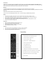
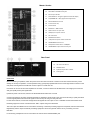
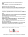
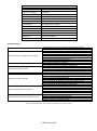
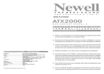
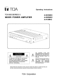
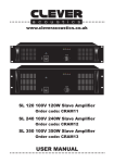
QMP240 powered mixer 178.602 User Manual Features: Built-in USB audio player Internal 16 program digital delay 3 Mic/Line + Stereo Line channel 2-band EQ per channel +48V phantom power 5-band master graphic EQ 2 x 120Wrms internal power amp www.qtxsound.com Introduction: Thank you for choosing this QTX Sound QMP240 powered mixer. This product has been designed to offer reliable, sound reproduction for small to medium PA systems. In order to gain the best results from this equipment and avoid damage through misuse, please read and follow these instructions and retain for future reference. Warning: To prevent the risk of fire or electric shock, do not expose any of the components to rain or moisture. If liquids are spilled on the surface, stop using immediately, allow unit to dry out and have checked by qualified personnel before further use. Avoid impact, extreme pressure or heavy vibration to the unit. There are no user serviceable parts inside the mixer – refer all servicing to qualified service personnel. Safety Check that the supplied mains lead is in good condition and the mains supply voltage is correct. Ensure signal and speaker leads are of good condition – ensure that there are no shorted connections Ensure that the minimum combined speaker load for each channel is 4Ω Do not allow any foreign particles to enter the console through connectors, control apertures or vents Do not cover or obstruct cooling vents Placement Keep out of direct sunlight and away from heat sources. Keep away from damp or dusty environments. Ensure adequate access to controls and connections Ensure adequate air-flow for cooling Cleaning Use a soft cloth with a neutral detergent to clean the casing as required Use a soft brush to clear debris from the control surface and vents Do not use strong solvents for cleaning the unit. Channel Strip 1. XLR microphone or low impedance line input 2. Stereo line inputs L+R 6.3mm jack 3. Stereo line inputs L+R RCA 4. Selector button - Jack/USB or RCA input 5. Mono line input 6.3mm jack 6. Channel GAIN control 7. EQ: HIGH frequency level 8. EQ: LOW frequency level 9. SEND/FX level of AUX SEND or internal delay effect 10. PAN/BAL control for stereo position (Left - Centre -Right) 11. PFL (Pre-Fade Listen) for monitoring and gain setting 12. PEAK LED illuminates when channel is clipping 13. Channel fader Master Section 14. MAIN output L+R 6.3mm jack 15. AUX SEND + RETURN 6.3mm jack 16. REC output L+R RCA 17. DIGITAL DELAY – Program up/down buttons & display 18. FX/PARAMETER - delay regeneration adjustment 19. AUX RETURN level control 20. 5-band master EQ 21. FX level fader 22. MAIN LEFT + RIGHT faders 23. USB connector for pen drive 24. USB player transport controls 25. VU meter LEDs 26. POWER LED indicator 27. +48V phantom power switch & indicator 28. HEADPHONES level control 29. Headphones select button – MAIN/PFL 30. HEADPHONES output stereo 6.3mm jack Rear Panel 31. IEC mains inlet & fuse 32. POWER switch 33. Speaker outputs LEFT + RIGHT 34. Cooling vent Connection Before connecting to speakers, switch the power off and turn down all volume controls to avoid loud noises which may cause damage to the amp or speakers. Connect speakers using good quality speaker leads via the Left & Right SPK connectors on the rear panel, ensuring that the overall load on each output is no lower than 4Ω. If the main mix is to be fed to further amplifiers or recorders, connect to these from the MAIN OUT Left & Right jack connectors with good quality 6.3mm jack signal leads. If phantom power is to be used, switch in the PHANTOM button below the VU LEDs Connect microphones, DI boxes and other balanced low impedance audio inputs to the mono channels using a quality XLR lead. Connect high impedance and line level signals to the mono inputs using a 6.3mm jack lead. For the stereo channel, connect left and right line level signals via 6.3mm jack or RCA - selectable via the switch below RCAs Recording equipment can be connected via the “REC” outputs using a twin RCA lead The 6.3mm jack AUX SEND can be connected to monitoring or external processing equipment if required, instead of the internal Digital Delay and the output of external processing equipment can be brought back into the mix by connecting it to AUX RETURN. For monitoring, headphones can be connected to the 6.3mm stereo HEADPHONES jack. With all faders down, connect the supplied mains lead to the mains supply and IEC inlet (ensure correct supply voltage). Switch POWER on and the “ON” LED will illuminate (if phantom power is selected, the “+48V” LED should light also) Checking Set all HIGH, LOW, PAN and BAL controls to the mid position (12o’clock) and SEND/FX controls to zero. Set all Graphic sliders to the mid position. Test each channel’s gain level by pressing in the PFL (Pre-Fade Listen) switch. If any PFL switches are on, the VU meters will display the output of the PFL channel(s) instead of the overall output. Make the loudest expected sound through that channel and increase the GAIN control until the signal reaches the 0dB mark. Dynamic attacks, like the strike of a drum or pluck of a string, may be allowed to go into the amber coloured LEDs (up to +7dB). Each channel also has a PEAK LED at the top of the channel fader. Momentary “blinking” of this LED is acceptable but prolonged illumination of this means that the GAIN should be turned down. Once the GAIN is set, switch off the PFL for that channel and repeat the process for all other input channels. Test the main mix output by gradually increasing the MASTER faders and selected channel faders whilst making sound through the channel(s) – the L + R output LED ladders should begin to show the output as it varies up and down. Output will be heard through any connected headphones or speakers. Operation Each channel has a 2-band EQ (LOW /HIGH), which can be used to balance the mix of frequencies and emphasise certain aural characteristics in the signal. Adjust these as required, noting that and overall increase may require an equivalent reduction of the GAIN control to compensate (otherwise clipping may occur from EQ boost). Use the PAN or BAL control to position the channel input either to the left or right side of the stereo field. This can be useful to help separate and define sounds within a mix but be aware that extreme settings can be counter-productive by removing the channel from certain listening positions. The MAIN/PFL button toggles the headphones output between MAIN mix and PFL, which allows a channel to be heard via headphones even when the channel fader is fully down. This can be useful if a DJ or presenter wishes to “Cue up” a track ready for playback. The HEADPHONES rotary controls the output level to headphones. Each channel has a SEND/FX control which determines the amount of the signal to be fed to the internal DIGITAL DELAY. If external processor(s) are to be used, pressing in the SEND/FX button switches the feed away from the internal DIGITAL DELAY and sends it to the AUX SEND output. The internal digital delay has 16 presets, selected via up/down PROGRAM buttons and shown on a numerical LED display The feedback or regeneration of each DIGITAL DELAY preset is controlled by the FX/PARAMETER rotary control. The level of AUX RETURN signal input is controlled via the AUX RETURN rotary control. Overall effect level fed to the mix is controlled via the FX fader. Channel faders should be used to adjust the individual levels in the mix and the MAIN faders are for overall output level. An onboard digital USB PLAYER allows the user to connect a memory stick to the USB connector next to the MAIN OUT jacks. The output of the USB PLAYER is fed to the mix via CH4 in place of the L & R jack inputs. Transport buttons, sited below the USB connector allow navigation of audio files as follows. Tone shaping for the overall mix can be adjusted via the GRAPHIC EQUALISER sliders from bass frequencies on the left to treble frequencies on the right. Turn down MASTER levels when changing any connections or powering down the mixer to avoid speaker damage. SPECIFICATIONS Power supply Power rms : 4 Ohms Power rms : 8 Ohms Inputs : Mic/Line Inputs : Line Phantom power Effect presets Speaker outputs Output : Mix Auxillary output EQ controls Dimensions Weight 220-250Vac, 50Hz 2 x 120W 2 x 80W 3 balanced XLR/6.3mm jack 1 stereo L+R 6.3mm jack/RCA +48V to XLR inputs (switchable) 16 x digital delay settings 2 x SPK connectors 2 x 6.3mm jack + Rec. out (L+R RCA) Aux send and return (6.3mm jack) High + Low channel, 5-band master EQ 300 x 135 x 320mm 5.48kg Troubleshooting No power LED on control panel Power LED is on but no signal LEDs or output Power light and VU LEDs lighting but no output No output from stereo channel VU LEDs do not show MASTER output level Output is very loud or distorted Output is working but at very low level Feedback (loud squealing or howling from mics) Ensure power lead is in good condition and connected properly Check IEC fuse – if continually blowing fuses, refer to service personnel Check input signals and condition of connection leads Check GAIN is not too low on channel input Check channel fader, GAIN and EQ controls are not turned fully down Check MASTER faders are not fully down For condenser mics, turn down MASTER faders and check phantom is on Check that PFL buttons are all switched out Check that all Graphic EQ sliders are not fully down Check output connections to speakers Check that PFL buttons are all switched out Check that mono input is connected to L/MONO jack Check that the Input select button is switched to the input being used If using jack inputs, remove USB stick If using USB, check that track is not stopped (press play button) Check that PFL buttons are all switched out Check level of input signal is not too high Reduce channel GAIN and EQ settings Reduce channel and MAIN faders levels Ensure Hi-Z line level input(s) not connected via XLR Check output levels of equipment connected via channel inserts Check AUX SEND / FX level controls and reduce if necessary Check gain level of recorded material on USB device Check input audio source level is not too low Ensure low impedance line or mic signal is not connected via jack Increase channel GAIN control and EQ settings if turned down Increase channel and MAIN faders levels Check level of recorded material on USB device Face microphone away from speakers and monitors Reduce channel GAIN level and EQ level(s) Reduce AUX / EFFECT levels Reduce channel and/or MAIN fader levels Note: for further troubleshooting, refer equipment to qualified service personnel for testing © QTX Sound 2011