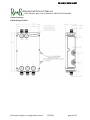
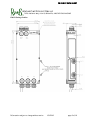
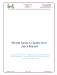
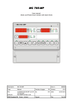
1
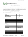
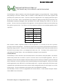
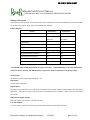
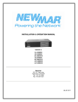
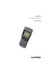
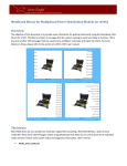
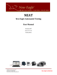
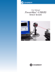
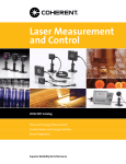
PM FAMILY DATA SHEET
RINEHART MOTION SYSTEMS LLC
7929 SW Burns Way, Suite B, Wilsonville, OR 97070 503.344.5085
AC Motor Controller for Electric and Hybrid Vehicles
Product Summary
The Rinehart Motion Systems LLC (RMS) PM Family of AC Motor
Controllers are designed for on- and off-road Electric (EV) or Hybrid
Electric (HEV) applications.
The motor controller converts the DC
power from the vehicle ESS (Energy Storage System / Battery) to the 3-phase AC required by the motor. These
Traction drives are fabricated using a patented high heat flux thermal design approach that dramatically reduces the
size and weight of the finished drive, and improves its life in the automotive environment. With extensive experience in
automotive and military vehicle traction and power electronics applications, RMS has achieved a major breakthrough
in integrating Motor Control into a vehicle.
RMS offers several different models within the PM Family of motor controllers to suit the DC bus voltage and motor
current requirements of your specific vehicle. The PM Family has been designed to operate with many types of
motors, including Induction Motors (IM) and Permanent Magnet motors (PMSM or IPM). Contact RMS for the
latest list of motors supported by our controllers. The Drive can also be tuned to your new motor - contact the factory
for more information.
The primary difference between models in the PM Family is the rated voltage and current (ultimate power output):
Controller Model
Maximum DC Voltage –
PM100DX
PM100DZ
PM100DXR *
PM150DX
PM150DZ
360 V
720 V
400 V
360 V
720 V
500 V
900 V
500 V
500 V
900 V
Motor Current Continuous
300 Arms
150 Arms
300 Arms
450 Arms
225 Arms
Motor Current Peak **
350 Arms
200 Arms
450 Arms
450 Arms
300 Arms
440 μF
280 μF
440 μF
880 μF
560 μF
See drawing
See drawing
See drawing
See drawing
See drawing
7.5 kg
7.5 kg
7.5 kg
10.7 kg
10.7 kg
operating
Maximum DC Voltage –
non-operating
DC Bus Capacitance
Size
Weight
Minimum Conductor Size
4 AWG
2 AWG
4 AWG***
Maximum Conductor Size
1 AWG
3/0 AWG
1 AWG
Minimum Cable O.D.
9.0 mm
11.0 mm
Maximum Cable O.D.
16.5 mm
21.0 mm
* The PM100DXR is only available for special applications (i.e. racing), use must be approved by RMS.
** Peak current is defined as a maximum of 30 seconds.
*** Depending on cable, it may be necessary to add additional sleeve to cable to meet the minimum Cable O.D. of the cable gland.
Information subject to change without notice
1/5/2012
page 1 of 10
PM FAMILY DATA SHEET
RINEHART MOTION SYSTEMS LLC
7929 SW Burns Way, Suite B, Wilsonville, OR 97070 503.344.5085
Power Production and Controller Ratings
The mechanical power that can be generated by any motor controller is highly dependent on the motor characteristics.
It is possible to estimate the actual motor output power you can achieve in any specific system if certain motor
characteristics are known. A common misconception is that Motor Current times DC Bus Voltage will give the motor
power. THIS IS INCORRECT.
First, it is important to know the continuous and maximum (peak) motor current ratings. It is possible that the
maximum motor current could be higher than the current rating of the motor controller. If so, then either a higher
current controller can be considered or use the motor controller current limits in the below equations.
The next important item to understand is the maximum motor voltage. In many circumstances the maximum motor
voltage is limited by the available battery voltage. The available motor voltage from the Drive output terminals is a
function of the DC bus voltage:
For example, if the Battery pack voltage is 320V then the motor voltage the inverter can make can never exceed
226.27VRMSl-l. In practice the actual voltage is generally limited to ~95% of this value, so for design purposes the
maximum motor voltage should be assumed to be 215.0 VRMSl-l(max). As the motor speed varies, the Drive will vary its
output voltage to deliver the required power – until it reaches this hard limit due to the battery voltage. You can’t get
any more. To go faster, the motor has to enter “field weakening”, where the Drive adds current to defeat some of the
permanent magnet field, so the motor output voltage is reduced and stays below the hard limit – in this case 215VAC.
If the maximum motor rated current is 300 Arms, you still can’t calculate how much mechanical power you can deliver
without knowing the motor Power Factor and efficiency at that operating point.
It’s not just how much current is flowing into the motor, but when it flows – its phase shift. Power Factor represents
the 3-phase system phase shift that exists between the motor voltage and the motor current. The motor power factor
varies from each different motor, motor type, and operating point. For this example assume a motor power factor of
0.768. Motor efficiency will also vary from motor to motor and over the speed/torque operating plane. Assume
motor efficiency is 91.2%, typical of an SPM motor at peak load. We now have enough information to calculate the
motor output power.
For this example we get:
Information subject to change without notice
1/5/2012
page 2 of 10
PM FAMILY DATA SHEET
RINEHART MOTION SYSTEMS LLC
7929 SW Burns Way, Suite B, Wilsonville, OR 97070 503.344.5085
The DC Input Current to the motor controller is based on the motor input power and the efficiency of the motor
controller. The motor controller efficiency will vary depending on the load conditions. However, for most high
power conditions a typical efficiency of the PM Family of controllers is 97%. The total system efficiency can be found
by multiplying the motor efficiency by the controller efficiency. For this example we would multiply 91.2% with 97%
giving a system efficiency of 88.5%. The DC input power can now be calculated as:
DC_Power = Pmech / .885 = Vbatt * Ibatt = 88.36kW
To continue the example, the DC current would be 276 amps at 320V battery voltage (88.36kW/ Vbatt)
General Specifications for the PM Family
Description
Value
Short Circuit Protection
Yes
Hardware Over-current Protection
Yes
9 .. 16VDC (12V Systems)
Vehicle System Power
-40 .. +80ºC
Operating Temperature Range – coolant water – no
derating
Isolation – High-Voltage to Low-Voltage
1000Vrms
Isolation – High-Voltage to Case
1000Vrms
Isolation – Low-Voltage to Case
50V
-40.. +105ºC
Operating Temperature Range – coolant water – derated
output power
Non-Operating Temperature
-40 .. +115ºC
Storage Temperature
-55 .. +105ºC
Coolant Type
50/50 EGW
Coolant Flow Rate
8 – 12 LPM
0.2 bar for PM100xx
Coolant Pressure Drop
0.25 bar for PM150xx
1.4 bar
Maximum Coolant Pressure (above ambient)
Operating Shock (ISO 16750-3, Test 4.2.2.2)
Operating Vibration (ISO 16750-3, 4.1.2.4 Test IV)
2
500 m/s (50g), pending testing
27.8 m/s2 (3grms), pending testing
IP6K9K
Environmental Protection Class (see ISO 20653)
IEC, pending testing
EMC compatibility
Information subject to change without notice
1/5/2012
page 3 of 10
PM FAMILY DATA SHEET
RINEHART MOTION SYSTEMS LLC
7929 SW Burns Way, Suite B, Wilsonville, OR 97070 503.344.5085
The PM Family of Motor Controllers comes with cable glands designed to accept shielded cable. Proper shielding
and grounding of the motor controller cables is essential to control EMC that can effect motor operation and
potentially other systems on the vehicle. The motor controller is designed with a wire clamping system that requires
the use of a wire ferrule. Refer to the PM Family User’s Manual on making the High Voltage Connections to the
PM100.RMS recommends Champlain Cable type EXRAD XLE 1000V shielded power cables for use with our
products. The size of the wire used depends on the application – the motor peak and continuous current and how long
those peaks are expected to last. For reference a size versus ampacity (continuous current handling capability) chart is
copied here:
Wire Size
Ampacity
4 AWG
190
2 AWG
255
1 AWG
293
1/0 AWG
339
2/0 AWG
390
3/0 AWG
451
Each controller contains a significant amount of DC bus capacitance. It is necessary for the user to provide a
pre-charge circuit for this capacitance. The PM motor controller does not present any practical limits on how small or
large the pre-charge current is. However, the user should take care to design the circuit so that if the controller were to
fail shorted the pre-charge circuit is not damaged and cannot start a fire. Pre-charge circuit operation may be
controlled by the internal software - refer to the PM100 User’s Manual for more information.
Control Software
The PM Family of motor controllers comes with advanced motor control software developed by RMS. This software
includes many features that are useful for control of an electric motor in an EV/Hybrid application. There is a
rudimentary Vehicle Controller (simplistic VCU functionality) in the drive that may be enabled to operate the attached
motor on the bench, or to drive a prototype vehicle around the parking lot in system integration. However, most safety
sertified applications use the PM Drive as a CAN-based output node – a separate computer (the VCU) issues torque
commands and reads feedback from the motor (and the battery management system, the driver inputs, etc) over the
CAN serial port. For more information on the software refer to the PM100 User’s Manual.
The PM Family of Drives can also be programmed with custom software, or with customer developed software.
Contact RMS for more information.
Information subject to change without notice
1/5/2012
page 4 of 10
PM FAMILY DATA SHEET
RINEHART MOTION SYSTEMS LLC
7929 SW Burns Way, Suite B, Wilsonville, OR 97070 503.344.5085
Hardware Description
The following section provides a brief description of the I/O hardware features of the PM family of motor controllers.
To use these I/O features, please refer to the PM100 Users Manual.
Feature Summary
Generation 2*
Feature
Generation 3*
Analog Inputs (0 – 5V)
4
6
RTD Inputs
2xPT100,
2xPT100/PT1000,
2xPT100
Selectable
Digital Inputs
6
8
High Side Outputs
2
4
Low Side Outputs
2
2
Resolver Interface
Yes
Yes
Quadrature Encoder Interface
Yes
Yes
Hall Effect Sensor Interface
No
Yes
CAN Interface
Yes
Yes
RS-232 Interface
Yes
Yes
* The PM150 family is implemented with Generation 3 Features. The PM100 family is currently implemented
with Generation 2 Features, The PM100 family is expected to change to Generation 3 in Spring of 2012.
Analog Inputs:
Intended for general analog signal sensing (0 – 5V).
RTD Inputs:
Used to sense temperature.
Digital Inputs:
Intended for general interface to the vehicle and for feedback from external contactors and switchgear as required in the
application. There are two types of inputs Switch To Ground and Switch To Battery. Refer to the user’s manual for
more detail.
High-Current Digital Outputs:
High side outputs can be used for driving 12V loads.
Low-side Outputs:
Low side outputs can be used for driving 12V loads that switch the ground side of the load.
Information subject to change without notice
1/5/2012
page 5 of 10
PM FAMILY DATA SHEET
RINEHART MOTION SYSTEMS LLC
7929 SW Burns Way, Suite B, Wilsonville, OR 97070 503.344.5085
CAN Interface:
There are two CAN2.0B compliant serial ports, capable of operation at 100k, 250k, 500k, and 1Mb/sec by software
selection. The CAN terminator for each port can be applied or opened under software control during setup or at any
time. EMI filtering for common-mode and differential-mode noise, and transient suppressors are used to improve the
robustness of the serial I/O system. Refer to the PM100 CAN Manual for more information on the protocol
implemented by RMS.
RS-232 Serial Interface:
There is one RS-232 serial interface with EMI filtering. This port can be used to set up and tune the controller, and to
download controller software updates from a computer. RMS offers a simple serial user monitor that runs on the PC
to allow changing parameters, changing the I/O functionality to suit the application needs, and other user-selectable
optimizations.
Encoder Interface:
For applications that use an incremental optical or magnetic encoder, there is a 5V interface to power the external
encoder and to receive, level translate, and filter the signals from A, B and INDEX channels. The sensor interface is
designed to work with an open collector type sensor. The maximum frequency of the interface is 50 kHz. The DSP
has specific hardware for wide dynamic range speed and angle calculation from the encoder data.
Resolver Interface:
A resolver can be used in place of the incremental encoder to determine machine rotor position and velocity. The
resolver is excited by a precision sinusoid, and the sine and cosine winding outputs are filtered for noise and presented
to the DSP to be digitized at 12b resolution. Due to the nature of the resolver interface the resolver excitation
frequency is the same frequency as the PWM frequency.
Hall Sensor Interface:
A Hall Sensor Interface is provided for motors that use this type of position sensing. The interface includes A,B,C
channel inputs as well as providing 5V power for the sensor. The sensor interface is designed to work with a
open-collector type output.
Low-Voltage Signal Connector Interface:
The PM Family motor controllers use two connectors for the low-voltage signals (Tyco/AMP AMPSEAL family).
The following connectors are used:
Connector
Connector Type
Mating Connector
Mating Contact Type
Type
J1 (35 pin)
Tyco/AMP 776231-1
Tyco/AMP 776164-1
Tyco/AMP 770854-1
J2 (23 pin)
Tyco/AMP 776228-1
Tyco/AMP 770680-1
Tyco/AMP 770854-1
Note: It is extremely important for proper operation of the connector to utilize the recommended crimp tool from
Information subject to change without notice
1/5/2012
page 6 of 10
PM FAMILY DATA SHEET
RINEHART MOTION SYSTEMS LLC
7929 SW Burns Way, Suite B, Wilsonville, OR 97070 503.344.5085
Tyco/AMP (Tyco/AMP part number 58529-1). A connector kit is available from RMS that includes the mating
connectors and 60 contacts (RMS p/n G1-0001-01).
The AMPSEAL contact is designed to work with 16-20 AWG wire with an insulation diameter between 1.70 – 2.70
mm. Make sure that the wire used conforms to these requirements.
Information subject to change without notice
1/5/2012
page 7 of 10
PM FAMILY DATA SHEET
RINEHART MOTION SYSTEMS LLC
7929 SW Burns Way, Suite B, Wilsonville, OR 97070 503.344.5085
Outline Drawings:
PM100 Package Outline:
Information subject to change without notice
1/5/2012
page 8 of 10
PM FAMILY DATA SHEET
RINEHART MOTION SYSTEMS LLC
7929 SW Burns Way, Suite B, Wilsonville, OR 97070 503.344.5085
PM150 Package Outline
Information subject to change without notice
1/5/2012
page 9 of 10
PM FAMILY DATA SHEET
RINEHART MOTION SYSTEMS LLC
7929 SW Burns Way, Suite B, Wilsonville, OR 97070 503.344.5085
Contacts:
SALES USA
SALES ASIA
Contact: Rich Swortzel
Contact: Dr. Steve Shi
New Eagle Business Development
Eontronix Co. Ltd.
[email protected]
[email protected]
734-649-8156 Voice
734-330-3800 Voice
928-395-2114 Fax
734-468-4085 Fax
www.neweagle.net
www.eontronix.com
FACTORY
Rinehart Motion Systems
[email protected]
503-344-5085 Voice
503-682-9014 Fax
www.rinehartmotion.com
Information subject to change without notice
1/5/2012
page 10 of 10