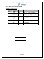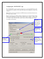
1
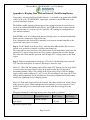
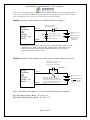
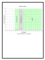
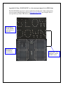
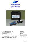
“SLOW DOWN”
OEM Radar Speed Sign Kit
Installation and User Manual
K-Band Doppler Speed Measurement and Message Display Kit
Rev 1 September 14th, 2011
Amber LED option
Please inquire for
other color options.
Houston Radar “SLOW DOWN” sign User Manual
The Doppler radar module incorporated in this device complies with part 15 of the FCC
Rules. Operation is subject to the following two conditions: (1) this device may not cause
harmful interference, and (2) this device must accept any interference received, including
interference that may cause undesired operation.
Changes or modifications not expressly approved by the party responsible for compliance
could void the user's authority to operate the equipment.
Any modification or use other than specified in this manual will strictly void the
certification to operate the device.
The radar in this device carries FCC modular approval and as such is labeled with FCC
ID TIASS300. If this label is not visible when the module is installed inside another
device, then the outside of the device into which the module is installed must also display
a label referring to the enclosed SS300 module. This exterior label can use wording such
as the following: “Contains Transmitter Module FCC ID: TIASS300” or “Contains FCC
ID:
TIASS300.” Any similar wording that expresses the same meaning may be used.
Warning: The “SLOW DOWN” kit is supplied in an open frame format with exposed
electronics and thus is a static sensitive device. Please use static precautions when
handling. Warranty does not cover damage caused by inadequate ESD procedures and
practices.
Note: Specifications may change without notice.
Note: Not liable for typographical errors or omissions.
Page 2 of 21
Houston Radar “SLOW DOWN” sign User Manual
Table Of Contents
INTRODUCTION .........................................................................................................4
INSTALLATION ..........................................................................................................5
DIRECTION POINTING: ................................................................................................5
RECOMMENDED ENCLOSURE FOR THE “SLOW DOWN” SIGN:......................................5
HOOKUP:.....................................................................................................................7
Power Input:............................................................................................................7
Data/PC Connection: ..............................................................................................7
Measured Speed Output:..........................................................................................7
IO CONNECTOR SIGNAL DESCRIPTIONS: .......................................................................8
USE ................................................................................................................................9
COLLECTING AND ANALYZING IN-RADAR TRAFFIC STATISTICS............10
REAL TIME TRAFFIC STATISTICS IN THE RADAR:........................................10
Internal Clock:......................................................................................................10
CONFIGURING THE “SLOW DOWN” SIGN: .......................................................11
Rotary Switch Configuration ................................................................................12
Additional Configuration Options ........................................................................13
“SLOW DOWN” SIGN SPECIFICATIONS .............................................................15
GENERAL ...................................................................................................................15
APPROVALS................................................................................................................15
DATA INTERFACES .....................................................................................................15
OPTICAL ....................................................................................................................15
MECHANICAL .............................................................................................................15
PERFORMANCE ...........................................................................................................16
MECHANICAL OUTLINE DIMENSIONS:.............................................................17
APPENDIX A: KEEPING TIME WITH AN EXTERNAL CLOCK BACKUP
BATTERY ...................................................................................................................18
Page 3 of 21
Houston Radar “SLOW DOWN” sign User Manual
INTRODUCTION
Congratulations on your purchase of the Houston Radar directional Doppler radar
“SLOW DOWN” message sign kit. This state of the art speed triggered “SLOW DOWN”
message display with integrated ultra-low power 24GHz K-band microwave Doppler
radar is specifically designed for the license free solar power or battery operated traffic
calming sign market. It may also be operated off AC mains by using a simple and
inexpensive off-the-shelf AC to DC converter.
Utilizing high performance, ultra low power DSP (Digital Signal Processing) technology
and microwave components based on a planar patch array antenna with integrated low
power PHEMT oscillator, you will find that this high quality product meets your exacting
standards for performance and reliability.
Some of the highlights of this product include:
Zero cables highly integrated design assembles into your enclosure in minutes
9.5” (24cm) message height is matched to 300+ ft (90+ m) detection range of the
radar for optimal display legibility
Best in class power efficiency achieved by:
• Low power SS300 radar directly drives display thus eliminating display controller
• Built-in ambient light sensing and automatic brightness control
When no traffic is present, the radar automatically powers down display further
reducing power consumption to only 0.1W
Wide input supply voltage operation allows flexible power supply options ranging
from 3, 4 or 5 cell Lithium Ion packs to 12V Lead Acid batteries
Built-in rotary switch allows user to set cutoff and violator speed alerts in the field
without connecting to a computer
Built-in radar is FCC approved with CE mark and available in 24.125GHz and
24.200GHz versions for worldwide deployment
Advanced In-Radar Traffic Statistics collection option now available
The “SLOW DOWN” message board is also available without the in-built
Doppler radar. In this configuration it may be triggered as a slave by our PNL10
speed display kit above a pre-determined speed threshold. This makes for a very
inexpensive option to add a “SLOW DOWN” message to the PNL10 and further
enhance the value of the PNL10. See Appendix B for details.
Page 4 of 21
INSTALLATION
“SLOW DOWN” sign is supplied in an “open frame” format. It requires a weatherproof
enclosure before it may be operated outdoors.
Direction Pointing:
The SS00 radar used in the “SLOW DOWN” sign is directional in nature. It may
be configured to detect and measure the speed of incoming or outgoing traffic. It
then rejects traffic moving in the opposite direction. Direction of detection is
configured via a bit in the MO variable in the radar (or via the supplied Windows
configuration program). In the usual “traffic calming sign” configuration the radar
is set to measure and trigger the message off the speeds of incoming vehicles and
is the default shipped from the factory.
To achieve optimal performance please follow a few simple rules:
Sign should be pointed into the direction of oncoming traffic.
Sign should be placed along the size of the road to minimize the angle of the
oncoming traffic to the sign.
o If it cannot be placed right along the side of the road, it should be pointed
at least 100-150 feet up the road into oncoming traffic.
The radar in the unit may pickup rotating fans, compressor blades, etc. Avoid
pointing it at any machinery containing moving parts.
Sign should be mounted at least 3 feet high from the ground for proper operation
and at least 5 feet high for maximum pickup distance
Sign utilizes 15° viewing angle LEDs. For maximum visibility of the digits the
sign should be pointed at the incoming traffic with better than 10° accuracy.
Alternatively, the sign may be oriented towards traffic to maximize the LED
brightness from the desired viewing location on the road. We suggest providing
an adjustable mounting bracket for your enclosure that will allow at least a ±15°
horizontal rotation to allow the user to make an adjustment during installation.
Recommended Enclosure for the “SLOW DOWN” sign:
The “SLOW DOWN” sign display kit must be protected by a weatherproof enclosure for
outside use. The following needs to be observed for optimal performance:
1. Any plastic cover or window in front of the unit may be mounted as close to the
LEDs as desired. However, please consider any potential damage from flexing
due to an external impact on the sign face (vandalism, etc.) being transferred to
the “SLOW DOWN” sign. For maximum field reliability we recommend that you
Houston Radar “SLOW DOWN” sign User Manual
test the proposed enclosure design to ensure the front face does not flex
sufficiently to transfer an impact to the “SLOW DOWN” sign.
The “SLOW DOWN” sign provides a clear hole in the center to allow you to pass
a bracing standoff through it to transfer any face impact to the back of the
enclosure. Do not mount the “SLOW DOWN” sign using this center hole. The
center standoff should be mounted from the rear of the enclosure and clear
through the “SLOW DOWN” sign display PCB and stop at the front face. This
will allow any front face impact force to transfer to the rear wall of the sign
enclosure.
2. The optimum material for the front window/face is Lexan (Polycarbonate) plastic.
3. The optimum thickness of polycarbonate window/sign face is half wavelength at
24.125Ghz or about 3.5 to 3.7mm thick.
a. Commonly available ¼” thick Lexan is not optimal and will reduce pickup
range. 3/16” thick Lexan is a better choice if the recommended thickness
is not available. For metric sizes, 4mm thick Lexan is a reasonably good
choice.
b. Frosted (anti-glare) plastic have been successfully used as well. It does not
matter which side (into the sign or into the traffic) the frosting faces and is
left to your discretion.
4. Other plastic materials may be used as a front window, but the optimum thickness
will wary with the material’s dielectric constant. Please contact Houston Radar for
details.
5. If you want to make a metal mask to hide the electronics on the “SLOW DOWN”
sign PCB with holes for the LEDs to pass through, you must provide a plastic
window for the radar microwave beam to pass through. Contact us for the exact
location and size of this window.
A dxf drawing to use as a template for the metal mask is available. Please contact
Houston Radar for the drawing.
We strongly recommend that you prototype and test your enclosure on the road to
verify that the radar detection range is not affected by your choice of plastic and
mechanical design prior committing to full production.
Page 6 of 21
Houston Radar “SLOW DOWN” sign User Manual
Hookup:
Power Input:
The “SLOW DOWN” sign may be powered from a DC supply with output voltage
between 7.5 and 18VDC. This allows great flexibility in power options including 12V
(nominal) lead acid batteries (SLA), 3, 4 or 5 cell Lithium Ion (LiOn) or Lithium Iron
Phosphate (LiFePO4) cells. There is no other message sign in the world that even comes
close to the resulting ultra-low power usage of the “SLOW DOWN” sign. Competing
products may consume up to 5 to 10 times more power. This ultra low operational power
translates directly into a longer battery life or gives you an option to power the unit from
smaller batteries and smaller solar panels.
A convenient battery life calculator is available on our website to estimate the run time
under different traffic and power supply situations.
Data/PC Connection:
The “SLOW DOWN” sign features a standard RS232 interface that is used to configure
the sign as explained later in this document. It also sends out the measured speed over
this interface when a vehicle is detected which may be used by an external controller
board to monitor the speed measured by the radar in the “SLOW DOWN” sign kit or
display on a connect PC running our Stats Analyzer or Configuration software programs.
Measured Speed Output:
The “SLOW DOWN” sign will send out the speed via the ASCII interface as a 3-digit
speed with an optional direction indicator in standard resolution mode. Extended
resolution mode adds up to 3 digits after the decimal point. The format is:
[?,+]nnn[\r,\n] or in extended resolution mode [?,+]nnn[.n[n[n]]][\r,\n]
The format of the speed output can be adjusted to any combination of:
“?”: Optional prefix sent when 000 selected to be sent when no vehicles are detected
“+”: Optional prefix sent when nnn speed is sent for incoming vehicles
“nnn”: Three digit ascii speed in the units selected via the UN variable
“[.n[n[n]]]”: Optional decimal point with up to 3 digits of extended resolution selected
via UN variable.
“\r”: Carriage Return character, optional line ending
“\n”: Line Feed character, optional line ending
Please see serial port configuration section for details on how to select the above format.
The radar used in the “SLOW DOWN” sign is the Houston Radar SS300. Please see the
SS300 user manual for more details on setting the output format and decimal point
options.
Page 7 of 21
Houston Radar “SLOW DOWN” sign User Manual
IO Connector Signal Descriptions:
DB9 RS232 Female Connector:
Connector
Pin #
1
Signal
Name
+VCCNote 1
Direction
Description
PWR Note 1
Radar VCC (battery “+“ terminal) Note 1
2
RS232 TX
OUT
RS232 Serial port TX pin from sign
3
RS232 RX
IN
RS232 Serial port RX pin into sign
4
N/C
-
Do not connect
5
6
GND
N/C
PWR
-
Signal/PWR Ground
Do not connect
7
N/C
-
Do not connect
8
N/C
-
Do not connect
9
N/C
-
Do not connect
(wrt Radar)
Note 1: Pin 1 optionally connected to +VCC (supply +) if PCB pad labeled “DB9 PWR” near DB9
connector is bridged. This may be bridged by the OEM or by us if you require this feature.
This area left blank.
Page 8 of 21
Houston Radar “SLOW DOWN” sign User Manual
USE
Turn on the power to the “SLOW DOWN” sign to make it operational. The message will
illuminate for about 4 seconds and then blank out. The sign is now fully operational.
If the rotary speed switch is enabled (see later section on configuration), turn the speed
switch to the desired position (0 through 7) determined by the speed limits on the road to
set the low-speed display cutoff, flashing speed and the high-speed display cutoff.
Typically, users set the low speed cutoff and violator flashing speed at or just above the
speed limit on the road. For example, for a 25mph speed limit road, the violator limit may
be set to 26 mph. Since the sign does not display the vehicle speed, there is no chance of
“racing against the radar by miscreants” and the high-speed cutoff may be set to the
maximum value. The exact values are of course left to the judgment of the user.
No other action is required. The “SLOW DOWN” sign will illuminate the message when
an incoming vehicle is detected between the low-speed and high-speed limits. The
display will blink at about 1.4Hz rate if the measured speed is above violator speed. This
indicates to the driver that they are driving above the speed limit.
As long as the radar is tracking a target between the low-speed cutoff and the high-speed
cutoff, the radar will transmit the speed in user selected ASCII format over the serial
interface. This may be observed via our PC based configuration tool or captured by an
external user provided controller board. Monitoring or capturing this speed is not
required for normal operation of the speed sign.
Serial output is affected by low, high and violator speed configuration in the same way as
the display.
This area left blank.
Page 9 of 21
Collecting and Analyzing In-Radar Traffic Statistics
The “SLOW DOWN” sign supports optional “In-Radar” advanced traffic statistics
collection. This feature is sold separately. If this feature is enabled you may collect the
stored statistics by using the provided Houston Radar Advanced Statistics Analyzer
Windows program.
This program must be installed on a MS Windows 7, Windows 2000, XP or Vista PC (32
bit and 64 bit versions) and allows the retrieval of stored statistics from the radar by using
a PC serial port. It also has features to generate traffic reports, plot interactive graphs and
export the raw data to a MS Excel file.
Please refer to the on line help functionality of the program after you install it on your
computer for detailed instructions on how to use its functionality.
Real Time Traffic Statistics In the Radar:
The “SLOW DOWN” sign In-Radar stats software now features “real time” histogram
statistics. These are updated as soon as a vehicle is detected and may be read out as a
speed bin count “histogram”. Thus no historical records need be read out and parsed to
read statistics.
This feature requires a host program to be on-line to read the live statistics. Please contact
Houston Radar for more information if you are interested in acquiring live statistics from
the radar.
Internal Clock:
The “SLOW DOWN” sign has a built in clock/calendar function. This is used to
keep the time to date/time stamp the historical archive records saved by the Advanced InRadar traffic statistics collection feature that is available as an option in the radar.
The “SLOW DOWN” sign does not feature a clock backup battery. So
power must remain connected to the radar for the clock to keep time.
However an external clock battery may be connected to keep time while
“SLOW DOWN” sign goes into low power sleep mode. See Appendix A for
more details.
Configuring the “SLOW DOWN” sign:
The “SLOW DOWN” sign can easily be configured via a user-friendly MS Windows PC
based graphical user interface (GUI) software that makes this configuration a snap for the
end user.
Step 1: Power up the sign and connect to the DB9 connector on the back of the unit via a
PC COM (serial) port cable:
Step 2: Launch the provided Houston Radar Configuration tool or Houston Radar Traffic
Stats Analyzer MS Windows program. Click on File->Connect to Radar… and then click
on “Connect” button. Once the radar is found, click the “Radar Configuration” tab and
you should see this window.
Pick your
preferred units
here. Speed is
also sent in these
units over the
serial port.
Message will
flash above this
speed.
Message will be
illuminated
above this speed.
Sets how far
vehicles will be
picked up relative
to maximum range
of radar.
Rotary Switch Configuration
To setup the rotary switch, first enable the rotary switch GUI as shown below:
Enable the rotary
switch GUI. On
the “Hardware &
IO Configuration
tab”.
You will then be able to setup the rotary switch settings via the new “Detection Limits
Setup” tab that will be visible.
Houston Radar “SLOW DOWN” sign User Manual
The above partial window-capture shows the configuration for the rotary switch installed
on the rear of the “SLOW DOWN” sign. This screen is only visible if the “Show Rotary
Switch GUI” checkbox is checked in “Hardware & IO Config” tab.
You have three different options:
1. Rotary switch changes only the low limit:
Enable the rotary switch and have it select the low-speed, speed limit and highspeed limits in the sign (a blue line will be drawn from the “test rotary switch
position” to below the low limit and high limit sliders to remind you that they are
linked to the rotary switch).
2. Rotary switch changes all three limits:
Enable the rotary switch and have it only select the low-speed cutoff. The speed
limit and high-speed limits are then fixed and can be changed via the slider (the
blue line from the “test rotary switch position, speed increment to the bottom of
the LO limit slider is a visual reminder that the low limit is linked to the rotary
switch).
3. Manually set all three limits to fixed values:
Disable the rotary switch completely and manually supply fixed values for all
three limits. This option is for fixed installations where the sign will be mounted
permanently in one location and you know what limits will be required for that
location.
You can easily test your settings by clicking the “Check Limits” button and
then spinning the “Test Rotary Switch Position” up/down. This will adjust
the slider and show you the effective limits for each position.
Alternatively you can view and print the entire table for all switch positions
by clicking on the “Display Speed Limits Button” button.
Please note that spinning this “virtual” rotary switch does not affect the actual sign. To
change the speed limits in the sign, the actual rotary switch on the back of “SLOW
DOWN” sign needs to be adjusted. The simulated values are provided as a tool to check
what actual speed settings you will get when your configuration is saved to the sign.
Additional Configuration Options
The radar utilized in the “SLOW DOWN” sign is the Houston Radar model SS300. It
supports numerous other options like detection sensitivity, programmable serial port baud
Page 13 of 21
Houston Radar “SLOW DOWN” sign User Manual
rate, different measurement units (mph, kph, fps, mps) and fractional high precision
speed output over the serial port.
If you wish to configure these options, we recommend that you read the SS300 user
manual for more details or use the other tabs on this screen. Many settings have tool tips
that will pop up once you hover the cursor over them.
This area left blank.
Page 14 of 21
Houston Radar “SLOW DOWN” sign User Manual
“SLOW DOWN” sign SPECIFICATIONS
General
Operating Band
Frequency
Power Output
Antenna Beam Pattern
Polarization
Supply Voltage
Reverse Battery
Nominal Current Draw
(@12VDC including radar)
Operating Temp.
Weatherproof
IR Remote Programmable
K-Band
24.125 GHz ±50Mhz (US) or 24.20Ghz (UK, Australia)
5mW
45 deg x 38 deg
Linear
7.5V DC to 16V DC (18VDC Maximum)
Protected
Display blank: 9.5 mA
Display at night: 71 mA
Display at max brightness: 510 mA
-40°F to +185°F
(-40°C to +85°C).
No. User supplied enclosure required.
No
Approvals
Radar Approvals
FCC Part 15, modular approval (US Version), CE Mark.
Data Interfaces
Serial Communication
Data Rate
Data Connector
Power
RS232
1200 to 115200 baud
DB9 Female with RS232 levels wired as a DCD. Use 3 wires
straight through cable to PC RS232 port.
Wire pigtail. Can be user specified. Minimum quantity order size
may apply. Contact us for details.
Optical
LED Color
Brightness
Viewing Angle
ITE Amber (592nm ±4nm) for message.
10,000 nits (cdm) maximum, controlled automatically via
onboard light sensor
500nits at night minimum
15° cone off normal
Mechanical
Weight
Dimensions
Mounting
approx 450 grams (1 lbs)
11”x16”x1.1” (28 x 41 x 2.8 cm)
8x #6 screw plated through holes connected to system GND.
1x #6 center non-plated hole for passing bracing standoff from
the back. Do not use to mount “SLOW DOWN” sign PCB.
Page 15 of 21
Houston Radar “SLOW DOWN” sign User Manual
Performance
Resolution
Accuracy
Detection Range
±0.006 mph (internal and available on serial port) rounded to
whole mph (kph) when shown on display.
±0.4% of reading + 0.1mph
Typically 90+ m (300+ feet) for compact vehicles on open
and level road with radar mounted 1.5 m (5 feet) high and
pointed straight into oncoming traffic. 150+ m (500+ feet)
for larger trucks, lorries and vehicles with inherently large
radar cross-section. May vary with installation and road
conditions. Detection range specified is typical for speeds
between 20kph and 88kph (12 to 55 mph). It tapers off
below and above this speed range. At the low end of the
speed range (2mph (5kph), the detection range is about 34+
m (110+ feet). “SLOW DOWN” sign is not recommended
for roads with speeds above 90 kph (56 mph) due to
reduced range and tracking time. Contact Houston Radar if
a low speed operation (down to 0.25 mph) is required.
Page 16 of 21
Mechanical Outline Dimensions:
[Contact Houston Radar at [email protected] or 1-888-602-3111 for details]
This area left blank.
Houston Radar “SLOW DOWN” sign User Manual
Appendix A: Keeping Time With an External Clock Backup Battery
Our popular “Advanced In-Radar Traffic Statistics” is available as an option in the SS300
radar as well as the “SLOW DOWN” sign display (which uses the SS300 radar as the
speed measurement element).
The In-Radar traffic statistics option generates time-stamped historical records that are
saved in the on-board FLASH memory. Hence, the SS300 radar needs to keep calendar
date and time once it is set from a device (typically a PC running our configuration or
stats analyzer software).
If the SS300 is used in a configuration that may disrupt power, an external clock backup
battery must be connected as suggested below.
Note: Alternatively the clock may be manually reset from an external controller to the
correct time once power is restored.
Step 1: Set the “Enable Low Power Sleep” mode bit in the MD variable (this is factory
default so no operation is required if you have not changed it).
The radar will now enter low power sleep mode where it will maintain the clock once the
external VCC supply voltage enters the sleep region as shown in the provided diagram.
The radar will resume normal operation once the input VCC voltage returns to the “Run”
region.
Step 2: Setup an arrangement to switch in a 4.5V to 6.8V clock backup battery into the
VCC line once main power is removed. This may be done two ways:
Method 1: “Wire OR” the backup source and the main VCC through two low drop diodes
as shown on the next page. Diode voltage drop must be taken into account when
determining backup voltage. For example if the diode voltage drop is 0.6V the backup
supply voltage must be between 5.1 and 7.4 volt. We recommend a low drop (<0.3V) low
leakage diode particularly for the clock battery when using a lithium battery that cannot
tolerate any significant reverse charging current.
Method 2: If the main supply will not be removed, but rather switched off, install a Zener
diode across the power switch such that the radar continues to receive between 4.5 and
6.8VDC when the power is turned off via the switch (with the rest dropped by the
zenner).
The power consumed by the radar in low power sleep mode is as follows:
Installed Configuration
Microamps
Sleep Mode
Sleep Mode
Consumed in sleep
Enter Voltage
Exit Voltage
SS300 in “SLOW DOWN”
7V
nominal
8V nominal.
785 uA ±20 µA
sign display
6.5V min
8.7V max
Note 1: Connecting a RS232 cable to the radar or forcing the RS232 interface to ON does not
affect the sleep power usage.
Page 18 of 21
Houston Radar “SLOW DOWN” sign User Manual
Note 2: The radar power usage is approximately constant regardless of the input supply voltage
in the sleep region. This is different when the radar is in the operational region where is behaves
as a constant power device (current goes down with increasing voltage).
Method 1 to provide clock backup power (Wired OR with two supplies):
SS300
Standalone
Low Drop voltage diodes
to Wire OR the batteries.
+VCC
D2
+
OR
“SLOW
DOWN” sign
Display
D1
+
GND
Clock Backup Battery (4.7V
to 6.7V assuming 0.2v diode
drop).
Main Battery (8.6V to
18 V.
May be removed.
Backup battery will
provide power to
maintain clock.
Ensure it cannot be
removed or disconnected.
Note: Please use low forward voltage drop diodes to maintain efficiency. Also carefully
consider the reverse leakage currents if using a lithium backup battery which is very
intolerant of such currents. D1 could be a signal diode that has very low reverse
currents. D2 needs to be rated for >=1A.
Method 2 to provide clock backup power (main supply switched off but not removed):
Zener diode to drop enough voltage
from main battery to supply
between 4.5V and 6.5V to SS300
* See Note 1
SS300
Standalone
+VCC
+
OR
“SLOW
DOWN” sign
Display
GND
Main power ON/OFF switch puts
SS300/”SLOW DOWN” sign into low power
sleep mode when turned OFF. Zenner still
provides enough voltage and current to allow
SS300 to keep time with minimal power
usage.
Note 1: The zenner value should be “X” and satisfy the following two equations:
Eq1 fully charged battery: Bmax – X = 6.5 to 4.5
Eq2 fully discharged battery: Bmin – X = 6.5 to 4.5
Page 19 of 21
Main Battery (8.6V to 18
V.
May NOT be removed if
time is to be maintained
when switch is in OFF
position.
Appendix B: Using “SLOW DOWN” as a slave message triggered via a PNL10 sign
The SLOW DOWN sign may be ordered without the in-built radar. In this configuration,
it may be mated with and triggered by the Houston Radar PNL10 speed display above a
user specified speed limit. This allows you to build a very
Houston Radar
“SLOW DOWN”
board without inbuilt radar.
Houston Radar
PNL10 Radar
Speed Display.
1 wire trigger from
PNL10 to “SLOW
DOWN” board.