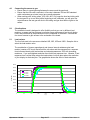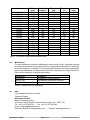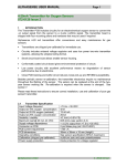
1
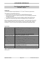
ALPHASENSE USER MANUAL
Toxic Sensor Evaluation Board
072-0128 Issue 4
Introduction
This Evaluation Board accepts Alphasense “A”, “B” and “D” Series toxic gas sensors.
The purposes of this evaluation board is to:
• help first time users of toxic gas sensors to evaluate Alphasense sensors;
• allow electronics designers to optimise potentiostat circuits by swapping op amps and
changing load resistor;
• let engineers study the effects of the bias voltage to optimise sensor performance;
• operate as a single channel gas detector with analogue output for laboratory use.
Before starting, please read these instructions carefully. You will need either four size AA
batteries (alkaline batteries are recommended) or a bench DC power supply, capable of
providing 6 to 9 volts at 1mA plus sensor gas hood, appropriate tubing and gas supply.
Specification
Power supply
Current requirement
Maximum output voltage
Sensor type
Sensors accepted
Sensitivity
rms. noise
Offset (zero gas) voltage
Output connector
DC power connector
PCB dimensions
Mounting
Operating conditions
Power supply protection
Sensor overload protection
Load resistor
Bias voltage
No-power circuit
Also required (not included)
6 to 9 VDC or 4 x AA batteries (alkaline recommended)
< 300 µA (battery life for alkaline AA: 9000 hours- 1 year)
±2.5 VDC(±250µ A) negative output voltage for oxidation current
three electrode electrochemical toxic gas sensors
Alphasense A,B and D toxic gas sensors
10µV/ nA
0.5mV (100Ω), 0.7mV (33Ω), 1mV (10Ω load resistor)
typically ±3 mV (equivalent to ±300 nA)
screw terminals
2.1mm DC jack socket (positive pin)
93 x 115 mm
four mounting screws into ABS box (100 x 119 x 41mm)
-30 to 50°C, 15 to 90%rh (noise increases below -10°C)
diode polarity protect: DC input & batteries
two diode pairs protect sensor from op amp latching
link selectable 10,33,47,100Ω
normal 0V bias; user adjustable bias voltage via on-board
potentiometer or external source.
shorting FET between working and reference electrodes 150Ω
batteries or DC source, sensor and gas hood, tubing, test gas
Table 1. Performance and environmental specifications for Alphasense Toxic Sensor Evaluation
Board Issue 4.
Alphasense Limited
Page 1 of 7
Evaluation Board Issue 4
1.0
Circuit Operation
The attached circuit diagram shows a potentiostat circuit at the top and the power supply
below. Refer to this circuit schematic during discussions below.
The potentiostat circuit is powered by ± 3VDC regulated supply. This supply is generated
from either four AA batteries or 6 to 9volt DC input. The DC input is diode protected
against reverse polarity. The batteries are also diode protected via D4, a zenner diode.
This zenner also disconnects the batteries when the circuit is continuously powered by a
DC external source. The linear voltage regulator (U5) provides the +3V supply and U6
generates the -3V supply. To monitor the power supply, use test points TP4, TP5 and
TP6, located to the right of the batteries.
The potentiostat circuit consists of three parts:
1
Control circuit (U1A or U4A)
2
Measuring circuit (U3A plus U4B or U2A)
3
A FET which shorts the working electrode (also called sensing electrode or SE) to
the reference electrode when power is removed from the circuit
1
The fixed voltage from the reference electrode is measured by either U1A or U4A
(depending on whether you are using two single or one dual op amp: see section 5.3).
The reference electrode (“Ref”) and working electrode (“SE”) are maintained at the same
voltage; if a bias voltage is applied via P5/P6 and LK2 then the working electrode
potential will be offset from the reference electrode voltage by the bias voltage. The
control op amp ensures adequate current is provided to the counter electrode (CE) to
balance the current generated at the working electrode, which is measured by U2A/U4B.
Circuit noise is reduced by the combinations of resistors R6 and R7 with C1. You may
find that only one resistor from R6 and R7 is necessary for your circuit design and the
value of C1 may need optimising.
2
It is normal to add a shorting FET so that the reference and working electrodes
are shorted together when power is removed from the circuit. If you remove LK1 then this
option is disconnected, but this means that when you switch on the potentiostat circuit in
the future the toxic gas sensor (SN1) will have been open circuit and may take a few
hours to stabilise. If you are biasing a gas sensor (see section below) then when you
switch off the circuit the reference and working electrodes will be shorted together. When
you reapply a bias voltage in the future it may take a few hours to re-stabilise to the bias
potential. Normally, no bias voltage is applied to the sensor via J2 and LK2 is fitted
between pins 1 and 2.
3
The measuring circuit is traditionally a single op amp. However, to offer maximum
flexibility in this evaluation board a two-stage op amp configuration has been used. The
second stage provides 10x amplification of the signal. This can easily be checked by
comparing the voltage of TP2 after the first stage and TP3 after the second stage. TP3 is
directly connected to the output at the screw terminal J3 on the top of the board.
The measuring circuit uses a combination of the load resistor (R1) plus the sensor
internal resistance along with the internal capacitance of the sensor to establish a RC
circuit. You can explore the effect of the load resistor by moving the link to LKA, LKB,
LKC or LKD and measuring the rms. noise with an oscilloscope and the response time
with a voltmeter or data-logger. Note that there is a compromise between fastest
response time (lowest resistance load resistor) and best noise (highest resistance load
resistor).
Alphasense Limited
Page 2 of 7
Evaluation Board Issue 4
A safety feature, D1 and D2, has been added to this circuit but is not normally
implemented in standard instrument/gas detector circuitry. The two pairs of diodes
protect the sensor from damage if the op amp clamps to the supply rail, hence driving too
much current back into the sensor and ruining the sensor. Op amp clamping can occur if
a sensor is plugged into an Evaluation Board that is already powered. Remember that
whenever the batteries are in place the circuit is powered. It is good practice to remove
the external power or at least one battery when plugging a sensor into the
Evaluation Board.
The attached schematic shows two parallel op amps for both control and measuring. You
only use one op amp in each case, but the circuit allows for either a single dual op amp
(labelled “DUAL” on the circuit board) or two single op amps (labelled U1 and U2). U3 is
always a single op amp and is not swapped. You can swap to equivalent op amps with
the same pin out during development (op amp pin out is shown in the schematic).
The output voltage is inverted; that is, a negative voltage represents a positive
current from the sensor electrode, and vice versa.
2.0
Connection and Wiring
Plug the sensor into the sockets on the top of the board. The sensor sockets accept
Alphasense type A, B and D toxic gas sensors.
If you are using an external DC power supply then the DC jack socket J1 accepts a
2.1mm DC plug with positive centre. Power is 6 to 9 VDC, with less that 1mA current
drain.
The output voltage is supplied at J3 on the top of the board through two screw terminals
with output and zero volts marked on the circuit board. Output is 10uV/ nA. See sensor
sensitivity specification to determine the expected output signal for a specific gas
concentration.
J2 (labelled BIAS and 0V) is normally not connected, but if you are applying an external
bias voltage then use J2 to inject the bias voltage. See section 5.4 below.
3.0
Power Supply
The dual mode power supply accepts either batteries or an external DC source.
Note the following points:
•
The circuit will operate as long as batteries are in place. There is no ON/OFF switch.
If you are not going to use the circuit for a long time then remove at least one battery
from the battery holder. New alkaline batteries will power the circuit for one year.
•
Although batteries provide a very low noise power supply source, since the ground is
not common to your measuring instrument a common mode voltage may cause
problems when using with a data-logger or meter powered by AC.
If common mode voltage is a problem then connect a wire from the zero volt pin
(TP6) to the ground point on your measuring equipment.
•
Avoid external DC voltage supplies with excessive noise or ripple.
Do not supply mains AC power to this unit: this will destroy the Evaluation Board.
Alphasense Limited
Page 3 of 7
Evaluation Board Issue 4
4.0
Connecting the sensor to gas
• Ensure there is a good gas seal between the sensor and the gas hood.
• Ensure that the flow rate is sufficient: a flow rate is between 300 and 500 standard
cubic centimetres per minute (sccm) are normally adequate.
• When working with “sticky gases” (H2S, NO2, NO, Cl2) purge the hood and tubing with
the test gas for up to one hour before beginning a test; otherwise, you will get a low
output because the test gas will stick to the tubing and gas hood before it gets to the
sensor.
5.0
Circuit options
The evaluation board is designed to offer flexibility so that you can try different load
resistors, op amps and bias voltages to optimise sensor performance and circuit design.
Links, test points and op amp sockets are on the underside of the board. Unscrew the
four corner screws to gain access to the underside of the board.
5.1
Load resistor
The four links next to the sensor are labelled 10R, 33R, 47R and 100R. Swap the link to
select the load resistor value.
The combination of (sensor capacitance) and (sensor internal resistance plus load
resistor) creates a RC circuit that affects the rms noise and the response time: response
time increases linearly with load resistor and noise decreases as 1/RC with increasing
resistance. If you need highest resolution then forfeit fast response time. Likewise, if fast
response time is critical then reduce the load resistor, but then also reduce the resolution
of your display to eliminate jitter. The graph below shows the effect of load resistance.
45000
40000
10 ohm s
35000
33 ohm s
Output (nA)
30000
47 ohm s
100 ohm s
25000
20000
15000
10000
5000
0
0
50
100
150
200
250
300
350
400
t (s )
Alphasense Limited
Page 4 of 7
Evaluation Board Issue 4
5.2
Shorting FET
LK1 (at the bottom edge of the board) connects the shorting FET, Q1. This shorting FET
is open circuit (> 1MΩ) as long as power is supplied from either the DC input or batteries.
However, when power is removed then the FET short-circuits (with a residual resistance
of about 150Ω) which ensures that the working electrode is maintained at the same
potential as the reference electrode. This “zero bias” power-off state ensures that when
you switch the circuit back on, the sensor is ready for use immediately. The FET is a p
channel FET from Siliconix. Alternatives are J175, J176 or J177.
If you are supplying a bias voltage, then when you switch off the circuit, the sensor will be
zero biased and hence when you reapply a bias voltage it will take a significant time (up
to several hours) for the sensor to re-establish equilibrium. Since the circuit takes so little
power it is easiest to ensure that the batteries are in place, leaving the circuit operating,
so long as your bias voltage remains on.
5.3
Swapping op-amps
As you look at the circuit board from the underside you will see that there is a quadrant of
four dual inline sockets for op amps.
• The bottom right socket (U3) houses a single op amp that is the second stage of the
two stage measuring circuit. You can swap this op amp (supplied: type OP90) for
another equivalent single op amp but it cannot be swapped for a dual op amp.
• The top left op amp socket (U4, labelled “DUAL”) accepts a dual op amp that
operates as both the controlling op amp (U4A) and the first stage of the measuring op
amp (U4B). You can remove the two single op amps (U2 and U3) and replace them
with a dual op (see pin outs in the schematic). This option allows you to measure
power consumption, zero offset and noise for a variety of single and dual op amps.
5.4
Bias voltage
Normally Alphasense toxic gas sensors are operated in the zero bias mode: that is, the
“BIAS” link LK2 (above the op amps) is connected between pins 1 and 2. However,
certain sensors (such as NO sensors) require a bias voltage. Alternatively, sensor
performance can be enhanced by adding a small bias voltage (BEWARE! performance
can also be degraded when biasing!). This is especially useful when cross sensitivity to
certain gases must be minimised. Consult Alphasense for further advice: remember that
biasing a normally unbiased sensor may damage the sensor and voids the sensor
warranty.
If you wish to inject a bias voltage then change the link LK to position 2+3 for an external
bias voltage, or 2+4 for the internally generated bias voltage. The internal bias voltage is
easy to use and avoids potential ground loop problems, so use the internal bias voltage
unless you are generating remotely time-dependent bias voltages. Using a digital
voltmeter, measure the bias voltage at J2 if using the internally generated bias voltage.
Adjust potentiometer VR1 to set the required voltage. The potentiometer swings from
positive to negative; so zero bias is about halfway on the potentiometer. NOTE: for
correct zero bias operation, use LK2 to link out the bias potentiometer. Do not use thVR1
to set zero bias voltage. Bias voltages can be set ±2mV that are adequate for settability;
bias voltage stability is about ±1mV, which will avoid transient sensor performance due to
fluctuating bias voltage.
Alphasense Limited
Page 5 of 7
Evaluation Board Issue 4
6.0
Noise, RFI/EMI Screening
Ideally, the measuring and controlling op amps in a potentiostat are directly underneath
the sensor because of the large capacitance of the sensor. This is not possible in this
Evaluation Board because of the need for user access to the op amps. Therefore, note
that the output noise from the circuit is not optimum: your design should be able to have
lower noise than this circuit. Where possible, good practice has been followed in this
circuit by, for example, designing copper grating on both sides of the PTH circuit board
helps to reduce stray electric fields. Alphasense Application Note AAN 103 gives further
advice on reducing noise and improving RFI/EMI screening.
7.0
Circuit Board Test Points
If you are concerned about the performance of the circuit or wish to monitor sensor
performance when gas is applied, then connect a high impedance voltmeter to the pins
shown in the table below, and labelled on the circuit board. See attached schematic.
Test Point
Purpose
1
counter electrode voltage
2
output voltage (first stage)
3
output voltage (second stage)
4
+3V regulated supply
5
-3V regulated supply
6
0V regulated ground
Table 2. Test Points for Toxic Sensor Evaluation Board
8.0
Calibration
The output from the Evaluation Board is scaled as 10 uV/nA; for example, a CO-BF
sensor will produce an output voltage of 1mV per ppm, since its sensitivity is 100nA/ppm.
Note that toxic gas sensor sensitivities are typically interchangeable ±15%, so although
the Evaluation Board accurately amplifies the output signal, you should calibrate to
correct for sensor-to-sensor sensitivity variations. Alphasense maintains a database of
the sensitivity of every sensor tested at Alphasense, but remember that sensitivity will drift
downwards with time, between 0.5% to 2% per month, depending on the sensor type,
relative humidity and gas concentration/ temperature conditions.
To determine zero voltage and sensitivity:
1
First ensure that the power supply is connected correctly (or that batteries are
fitted) and a good fitting flow-hood is in place.
2
Ensure that a high quality zero gas source is available (e.g. cylinder of artificial air
or cleaned and scrubbed compressed air) and a bottle of calibration gas with
validated accuracy (see Table 5 below).
3
Apply zero gas at 300 to 500 sccm for 10 minutes. Record the zero gas output.
4
Apply test gas at the concentration shown in Table 5 for ten minutes then record
the span output.
5
Subtract the zero mV from the span mV, then divide the corrected voltage by the
span gas concentration (as ppm) to determine: mV/ppm. This is your sensitivity.
6
If you apply the output voltage to an oscilloscope you can measure rms noise and
convert this noise reading into sensor resolution (as equivalent ppm) by dividing
this noise (as mV) by the sensitivity. If this resolution is not adequate for the
required stability (i.e. jitter) of the display on your instrument/ detector then the
sensor must be electrically screened to reduce noise susceptibility.
Alphasense Limited
Page 6 of 7
Evaluation Board Issue 4
Sensor
CO-BF, CO-B1
CO-BX/AF
CO-AX
CO-AE
H2S-AH
H2S-BH
H2S-A1/A2
H2S-B1
H2S-BE
H2S-AE
SO2-AF
SO2-BF
SO2-AE
NO2-A1
NO2-B1
NO2-AE
NO-A1
NO-B1
NO-AE
Cl2-A1
CL2-B1
Full-Scale
(ppm)
2000
2000
2000
4000
50
50
200
200
2000
2000
20
100
2000
20
20
200
20
20
1000
20
20
Sensitivity
(nA/ppm)
100
70
50
20
1200
1600
750
370
90
105
500
350
100
370
900
350
FS output
(µ
µA)
200
140
100
80
60
80
150
74
180
210
10
35
200
7.4
22
70
FS output
(V)
2
1.4
1
0.8
0.6
0.8
1.5
0.74
1.8
2.1
0.1
0.35
2
.074
0.22
0.7
100
370
900
100
7.4
22
1
.074
0.22
Cal point
(ppm)
400
400
400
1500
20
20
20
20
400
400
20
20
400
5
5
100
5
5
400
10
10
Table 5. Toxic sensor outputs and calibration points
9.0
Maintenance
The only maintenance required is changing the sensor-hood O-ring if it has been exposed
to extreme environments for long periods (this O-ring should last the lifetime of the sensor
in normal conditions). In addition, if the top dust/oil filter has become badly contaminated
then contact Alphasense for replacement dust/oil filter. Replacement O-rings and dust/oil
filters can be ordered by quoting the part number.
Part Number
033-0002-00
024-0011-00
024-0018-00
Description
Replacement O-ring (B series)
Self-adhesive dust/oil filter (B series)
Self-adhesive dust/oil filter (A series)
Table 3. Replacement Part Numbering
10
Help
If you need assistance then contact:
Customer Support
Alphasense Limited
Sensor Technology House
300 Avenue West, Skyline 120, Great Notley, Essex, UK CM77 7AA
Tel: +44 (0) 1376 556 700 - Fax: + 44 (0) 1376 335 899
E-mail: [email protected]
Web Sites: English: www.alphasense.com - Chinese: www.alphasense.cn
Alphasense Limited
Page 7 of 7
Evaluation Board Issue 4