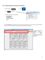
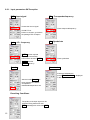
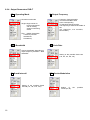
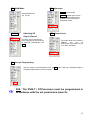
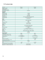
1
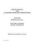
PCU 4111 PCU 4121 User manual MADE IN GERMANY 0901677 V1 Inhaltsverzeichnis 1. Hazards and safety instructions .......................................................... 3 2. General Information............................................................................... 5 3. Description ............................................................................................. 5 4. Scope of delivery ................................................................................... 5 5. Input Circuit ........................................................................................... 5 6. Assembly................................................................................................ 6 6.1. Earthing ............................................................................................................... 6 7. Installation.............................................................................................. 7 7.1. Pre-programming ................................................................................................. 8 7.2. Input Level ........................................................................................................... 8 7.3. Output Level ........................................................................................................ 8 8. Programming General ........................................................................... 9 8.1. Software Installation............................................................................................. 9 8.1.1. Installation of the Driver ...........................................................................................................9 8.1.2. Installation of the Programming Software ..............................................................................10 8.2. Programming of the Device Parameters ............................................................ 11 8.2.1. Input Parameters.......................................................... Ошибка! Закладка не определена. 8.2.2. Output Parameters .................................................................................................................14 8.3. Function "Service List" ....................................................................................... 18 8.3.1. Deletion and Addition of Services ..........................................................................................18 8.3.2. Selection of the TV Channels to be Decoded ........................................................................19 8.4. Saving of the Programming ............................................................................... 21 8.4.1. Saving of Settings ..................................................................................................................21 8.4.2. Loading of Settings.................................................................................................................21 8.5. LAN Function ..................................................................................................... 24 8.6. Diagnostics ........................................................................................................ 25 8.7. LED Key............................................................................................................. 25 8.8. Firmware- Update .............................................................................................. 26 8.8.1. CPU (µ Controller)....................................................... Ошибка! Закладка не определена. 8.8.2. FPGA (QAM- Modulator)............................................. Ошибка! Закладка не определена. 9. Application example............................................................................ 27 10. Technical data...................................................................................... 28 11. Declaration of conformity ................................................................... 29 2 1. Hazardsandsafetyinstructions Before working on the PCU4111/4121please read the following safety precautions and the safety Power supply and power cord The device must be operated only at a power supply with a voltage of 230 V / 50 Hz. Connection cable Place the connection cable always trip proof ! Replace the power cord only with an original power cord. Potential equalization / grounding Proper grounding and installation of the device must be carried out according to EN 60728-11 / VDE 0855-1 regulations. Operation without grounding or potential equalization of equipment is not allowed. Humidity and placement location The device must not be exposed to dripping or splashing water. If water condensation occurs, wait until the device is completely dry. The device must be installed on a vibration-free location. Ambient temperature and heat effect The maximum allowable ambient temperature is 45 ° C. The ventilation holes of the device must NOTbe covered under any circumstances. Too much heat or heat accumulation affect the life of the device and can be a source of danger. To prevent heat buildup and to ensure good ventilation, the device must be mounted horizontally (eg. on a wall). The device must not be mounted above, on top,or near heat sources (e.g radiators, heating plants), where the device is exposed to heat radiation or oil vapors. The installation must be done only in rooms that ensure compliance with the permissible ambient temperature range, even under changing climatic conditions. If the device exceeds the maximum operating temperature, it automatically switches to a reduced power consumption. The device is out of function during that time. Once the temperature has reached again the allowable range, it automatically switches back on. Warning: When installed in rooms such as storage or attic one should pay particular attention on compliance with the ambient temperature. Because of the danger of fire due to overheating or lightning strike, it is recommendable to install the device on a noncombustible surface. Combustible surfaces are wood beams or bars, wood boards, plastic materials, etc. 3 Conditions to ensure electromagnetic compatibility (EMC) All covers, screws and connectors must be securely mounted and tightened, contact springs must not be bent or oxidized. Opening the case ATTENTION Device’s caseopening and repairs must be performed only by authorized personnel. First to be done is to pull the network plug.Replacingof fuses must be done only with fuses of same type, value and melting characteristics. No maintenance work during storms ATTENTION This module contains ESD components! (ESD = Electrostatic Sensitive Device). An electrostatic discharge is an electrical current pulse, which can flow also through an electrically insulated material, when triggered by large voltage difference. To ensure the reliability of ESD components, it is necessary to consider their most important handling rules: Electrostatic sensitive components can be processed only on electrostatic protected area (EPA)! Pay attention permanently to potential equalization (equipotential bonding)! Use wrist straps, approved footwear for personnel grounding! Avoid electrostatically chargeable materials such as normal PE, PVC, polystyrene! Avoid electrostatic fields >100 V/cm ! Use only labeled and defined packing and transportation materials! Damage caused by faulty connections and / or improper handling are excluded from any liability. Waste disposal Electronic equipment is not household waste but should be properly disposed on electrical and electronic equipment waste - in accordance with Directive 2002/96/EC OF THE EUROPEAN PARLIAMENT AND COUNCIL. Please take this device at the end of its use for proper disposal at the designated public collection points. WEEE-Reg.-Nr. DE 51035844 4 2. General Information The PCU 4111/4121 is a modern, compact transmodulatorthat converts 4 signals DVB-S/S2, DVB-T/T2 or DVB-C in 4 DVB-C/DVB-Tchannelsand can decode encoded programmes using a suitable CI module. Its simple and quick assembly, configuration and programming means that it can be commissioned without problems. Up to 4 transponders from up to 4 different signals can be transmitted. This makes it possible to transmit SD and HD programmes via all transponders, regardless of whether these are encoded or nonencoded. 3. Description The compact headendPCU 4111/4121from POLYTRON converts four signals (DVB-S/S2, DVB-T/T2 or DVB-C) intoDVB-C/DVB-T signals. Thefour inputs are each provided witha Cl interface for decoding encoded signals. With this, QAM communal installationscan be simply and cheaply supplemented with centrally decoded ranges. Alsoconceivable is use as free-to-air basic supply in asmall boarding houseor hotel, because around 20 programmes of 4 transponders are already made available. The headend can be simply and quickly programmed via the USB interface. No knowledge whatsoeverthe assigningand administration of IP addresses is required for this. The selectedsettings can be printed and saved and also transferred to other devices with a USB-stick. Dueto the integrated LAN connection, it is possible to remotely control all parameters. The headend works in the frequency range 112 to 862 MHz and converts the selected satellitetransponders completely including the additional services Teletext, EPG etc. Theoutput is also suitable for adjacent channelsand hasalevel of 90 dBμV. The PCU 4111/4121has an energy-saving switching power supplywhich alsotakes over the supplying for the LNB input 1 and input 2. 4. Scopeofdelivery 1 x PCU 4111/4121 1 x Power cable 1 x USB-cable 1 x USB-Stick (Programming software) 1 x Operating instructions 1 x Installation accessories 1 x Drilling template 1 x LAN patch cable 5. Input Circuit InthePCU 4111/4121, thesignals are directly fed toinput tuners. Here there are 4SAT and 4 Ter. inputs. Atinput 1 and input 2 there is in addition 12V DC voltage for LNB supplying. 5 6. Assembly The installation of the compact headend must take place in a well ventilated room. The ambient temperature must not be more than 45°C. It must be ensured that the air can circulate through the ventilation holes. There must be at least 15 cm of space around the device, so that the air can circulate properly. The plug must be pulled from the socket before installation or work on the cabling. 15 cm 15 cm 6.1. Earthing The device must be earthed in accordancewith EN 60728-11. - Strip approx. 15 mm of the cable insulationof theearthing cable (4mm2). - Push stripped end under theearth screwand tighten the screw. 6 7. Installation Connection of the SATSignals Connect SAT signals directly or viasplittertothe sat tuner inputs. Atinput 1 there are 12 V DC for the supplying of the LNB. Pleasenote that the current consumption must not be more than 350 mA at the input. Insertion of the CIModules To insertthe CI modules, the covers must be removed. Use the picture to seehowthe CI slots are assignedto the SAT inputs. Always insert the modulewith the address facing forwards (in the direction of the lid). 7 7.1. Pre-programming The inputsand outputsof thedeviceare pre-programmed ex-factory with a german standard frequency allocation. In order to receive the pre-programmed ASTRA transponder, the SAT inputs must be connectedwith the"horizontal high“ level in accordance with thefollowing picture. Platz/ Slot Transponder Symbolrate ASTRA Ausgang/ Output 1 ARD Digital HH 11836 27500 kSym Das Erste BR FS Süd 2 ZDF Vision HH 11954 27500 kSym ZDF 3 Sat 3 SAT1 / Pro7 HH 12545 22000 kSym Sat. 1 Pro 7 4 RTL World HH 12188 27500 kSym RTL RTL 2 HR SWR BW WDR Köln BR FS Nord Ki.Ka ZDF Info ZDF neo ZDF kultur Kabel 1 N24 Sat. 1 Gold etc. VOX Super RTL N-TV etc. 306 MHz 314 MHz 322 MHz 330 MHz 7.2. InputLevel In order to ensure flawless reception,make sure that the level at theinputs is between 50 and 80 dBµV. When receiving digital signals it is advantageous to have a lower rather excessively high level. If the input level is too high, anattenuatoris to be used. 7.3. Output Level Upon delivery, the output level is90 dBµV. This can be changed via thedevice programming (see point 8.2.2). There is an output level reduced by 20 dB at the TEST socket. 8 8. Programming General After the mains cable is connected, the device runs through aninternal routine and all 4 channelsare set with the previously stored data. During this,the status LED next to the USB socket flashes green. Only after the status LEDis continuously green or orange, contact is possiblebetween PCU 4111/4121and Laptop/PC. 8.1. Software Installation Download thesoftware package from thehomepage www.polytron.de(satc12_Vxxx.zip)and unzip in the directory of your choice (e.g. C:\ PCU 4111). The software can also be loadedfrom the enclosed USB stick. 8.1.1. Installation of theDriver StartInstal_driver.cmd Follow theinstructions on the screen. In somefirst installations the following dialog can appear. This depends on the operating system. Carry out the following instructions and select theselection fields: no, not this timet next installSoftware automatically next 9 If this notice is displayed: Continue the installation The software was installed for the following hardware finish The installation of thedriver software is now complete. 8.1.2. Installation of the Programming Software Install thesoftware by starting the"Setup.exe"program in thedesired folder. Follow the instructions on the screen. Close the screen displays once the installation has ended. After the installation of the programming software on the PC, the PCU 4111/4121 can be connected to the PC with the USB cable. Only connect thedeviceto the PC once the software installation has been completed. 10 USB 8.2. Programming of the Device Parameters Start the program – SATC12 – Click on Menu at the top left The following menu points areavailable: ProgramMenu Diagnostic FirmwareUpdate Exit Select ProgramMenu: alladjustments of theinput and output parameters are carried out here. After thecalling of the menu, all 4 channels areand the respectiveadjustedparametersare displayed. In the top part of themenu, thedevice data is displayed, such astype, serial number, hardwareversion and the softwarestatuses for CPU and FPGA. 11 8.2.1. Input parameters SATreception DVB >Input signal TP > Transponderfrequency Chosse the kind of signal Enter transponderfrequency If DVB-T/T2 or DVB-C is choosen, go furtherin the passage TER. reception Auto > LO. -frequency SR >Symbolrate AUTO sets the required frequency automatically. Can however be set to 09750, Enter symbolrate 10600 oranother OTHER frequency. Search > Tuner Locked If thetuner findsthetransponder Tuner Locked is displayed in the upper field. After the button Search has been activated, the data is acceptedand thedesiredtransponder is set. Receiving Conditions The quality of the input signal can be evaluated using thebit error ratio BER andthesignal-to-noise ratio SNR . 12 The guidelines shown apply to the signal-to-noise ratio SNR. The corresponding values of the FEC (forward error correction) areto be taken from thetablesof the satellite operators.Ife.g. thetransponder has an FEC of 5/6, the SNR display must beat least 9 dB to guarantee good signals. 8.2.2. Input parametersfor Ter. range TP >Input Frequency FEC gut sehr gut 1/2 2/3 3/4 5/6 7/8 5‐7dB 7‐9dB 8‐10dB 9‐11dB 10‐12dB 8‐11dB 10‐13dB 11‐14dB 12‐15dB 13‐16dB BW >Channel Bandwidth The kind of input signal will be identified automaticly. Select input frequency PLP >Select Service (DVB-T2) 7 or 8 MHz Search >Searching After the button Search has been activated, the data is acceptedand thedesiredchannelis set. Select PLP If thetuner findsthechannel Tuner Locked is displayed in the upper field. Receiving Conditions The quality of the input signal can be evaluated using thebit error ratio BER and thesignal-to- The guidelines shown apply to the signal-to-noise ratio SNR. DVB-T should have a min. SNR of 26 dB and DVB-T2 of 32 dB. noise ratio SNR . Recommendation: bit error ratio BER should be ≤1e-6 13 8.2.3. Output Parameters OP > Operating Mode Normal>normal mode Single >single carrier for level measurement with an analog antenna measuring device Zero > digital channelwith content 0 (constant levelwithout fluctuations) BW > Bandwidth Choose bandwidth depending on output frequency between 7 MHz and8 MHz SR > Symbol Rate up to 7,200 kilosymbols/ sec. is dependent on theselected QAM mode(used setting incable networks: 256 QAM / SR 6.900). Only thesymbol rates that are possible are accepted. 14 F >Output Frequency Frequency freelyselectable. It is recommended to stick to the corresponding TV standard channel spacing. The frequencyof thechannel middle is set. (e.g. channel 21, 410- 478 MHz, set 474 MHz) QM > QAMMode Setting of the possible QAM mode (16, 32, 64, 128, 256) dependent on thedata rate of theinput transponder. Only the QAM mode that is possible is displayed SP > Spectrum Normal>normal mode Inverted>Useful signal can be inverted in itsspectral position. Inversion is only necessary in exceptional cases. On OFF > Switching Off Output Channel If not all 4 output channels are to be assigned, eachchannel can be switched offindividually with OFF. ATT >Output Level The output level at the output is 90dBµV and can be weakenedin each channel by up to 12 dB in 1dB steps. Set >Accept Programming After the setting of all parameters press theSet button. With this, theadjusted data is accepted. Repeat steps for other channels. N.B.: The DVB-C / QAM receivers must be programmed in accordance with the set parameters (search) 15 8.2.4. Output Parameters DVB-T OP > Operating Mode Normal>normal mode Single >single carrier for level measurement with an analog antenna measuring device F >Output Frequency Frequency freelyselectable. It is recommended to stick to the corresponding TV standard channel spacing. The frequencyof thechannel middle is set. (e.g. channel 21, 410- 478 MHz, set 474 MHz) Zero > digital channelwith content 0 (constant levelwithout fluctuations) BW > Bandwidth CR>Code Rate Choose bandwidth depending on output frequency between 7 MHz and8 MHz Setting of the possible Code rate (1/2, 2/3, 3/4, 5/6, 7/8) GI>Guard Intervall Setting of the possible Guard intervall (1/4, 1/8, 1/16, 1/32) 16 CM >Carrier Modulation Setting of carrier (2k, 8k) the possible QM>QAM Mode Setting QAM mode (16, 32, 64) On OFF > Switching Off Output Channel If not all 4 output channels are to be assigned, eachchannel can be switched offindividually with OFF. SP > Spectrum Normal>normal mode Inverted>Useful signal can be inverted in itsspectral position. Inversion is only necessary in exceptional cases. ATT >Output Level The output level at the output is 90dBµV and can be weakenedin each channel by up to 12 dB in 1dB steps. Set >Accept Programming After the setting of all parameters press theSet button. With this, theadjusted data is accepted. Repeat steps for other channels. N.B.: The DVB-T / COFreceivers must be programmed in accordance with the set parameters (search) 17 8.3. Function "Service List" If certain services within a transponder are not desired at the output, they can be removed. Encoded services can still be selected for decoding via this function. 8.3.1. Deletion and Addition of Services In addition to the"SearchButton“ anotherbutton -"Service List“ - is displayed. This is only active if the tuner is locked. If the data rate at the input is higher than the data rate that is possible at the output due to the set parameters an error message appears and thebutton for the Service List turns red. In this case, a reduced selection of the desired services must be made. The field Bitrate is marked by colors. Green means: The remaining bitrate is higher than 10000 kSym. Yellow means: The remaining bitrate is less than 10000 kSym. Red means: The remain bitrate is less than 5000 kSym. Overflow mean: The datarate is to big for the adjusted DVB-C parameters. Clicking on thisbutton opens the followingwindow. The list of services available at the input is shown on the left. On the right, one can see the services contained in theoutput signal. The standard setting after scanning is always "Transparent“ i.e. everything that is there at the input also appears at the output. Ifthe data rate at the output is too high, the word "Overflow" appears in the field Rem. Bitrate. This means that the data rate is too high for the set parameters, and services must be removed. Undesired services can of course also be deleted if there is no overflow. 18 By clicking on a service in the input list and clicking on thecommand"Add“, thisservice is added to the output list. (Double-clicking on a service in theinput list automatically adds it to the output list). Clickingon a service in theoutput list and clicking on the command "Remove“ removes this service from the output list. (Double-clicking on a service in the output list removes the service automatically). By single-clickingon the"Save/Back“ button, the output list is saved and thewindow is automatically closed. If you only want to accept a few services from a transponder that has many, you can first click on"Remove ALL“ and then select therequiredservices. The data rate still available is shown in the field Rem. Bitrate. This should be at least5.000kSym. 8.3.2. Selection of the TV Channelsto be Decoded After the CAM modulewith the appropriate smart card has been inserted in the CI slot, press the Service List button. All available services are displayed in theinputand output list. In theoutput list, now select the desired services to be decoded by placing a tick. In theoutput list, now select the desired servicesby placing a tick. Encoded and non-encoded services can be output together. With a click on the"Save/Back“ buttontheoutput list is saved and the window is automatically closed. The CAM modules should always be in a switched-off state when inserted. LCN function for the allocation of program positions 19 It is located under the menu item "Extras / LCN settings" The CHANNEL index indicates the channel strip that contains the channel. Storing the LCN settings In the LCN column, you can enter the desired program position. These programs are then sorted in order in the table. Programs that did’t get a posittion code will follow behind the marked programs. Premise is that the receivers support LCN 20 8.4. Saving of the Programming It is possible to save existingprogramming on a PC and/or to load it from a PC. Program combinations can thus be archived. Themain program is opened withthemenu point Settings 8.4.1. Saving of Settings Withthemenu point Save Settings it is possible to save theprogramming ontothe PC.A directory and file name (e.g. object) are to be entered for this. Thefile name must retain the ending .c12!! The the settings are also saved in an rft file. This is located in the same folder as the PCU 4111software. This file format can be opened, edited and printed withe.g. Microsoft Word, Open Office or wordpad. 8.4.2. Loading ofSettings With themenu point Load Settings it is possible to load existing programming fromthe PC onto a PCU 4111/4121. For this, the desired file name is to be selected and opened in the register. The date is automaticallyloaded. 21 Dual Channel Function For headend PCU 4111/4121 Application: The data rate of a transponder is to high to place the TV programs in one 7 or 8 MHz DVB-C channel. With the Dual channel function it´s possible to split ainput signal into two DVB-C output channel. Block diagram of the complete 4 channel If the Dual Channel Function is needed please click on following Button. The button is top right. It´s not possible to change the input parameter . It show the transponder, where the paramter could be changed. To activate the Dual Channel switch from OFF to ON. Now the output frequency and other parameters, for the second channel could be changed. The second output channel is totalyindepent from the first output channel. To save the parametersplease click „Set“. 22 Back to the main menu. To split the TV programs to both of the output channel, please click the Button „Service List“. If the second DVB-C output channel is switched on, then a blue script appear„DUAL active“. The table in the middle „Input Servicelist“ shows all channels of the transponder. With the button Add and Remove the TV programs can be allocate to the both outputs. To control the Bitrate please click the button “Check” The field Bitrate is marked by colors. Green means: The remaining bitrate is higher than 10000 kSym. Yellow means: The remaining bitrate is less than 10000 kSym. Red means: The remain bitrate is less than 5000 kSym. Overflow mean: The datarate is to big for the adjusted DVB-C parameters. To decode the favored TV programs a hook must be placed in front of the TV program name The Button „Save / Back“ the parameters will be saved and the main menu appears. 23 8.5. LAN Function Click onProgram Menu to open the programming environment. The basic settings are loaded and the user interface is started. The PCU 4111/4121possessesthe IP address: 192.168.1.227 as a standard setting. If the system is used in a network with a different network address, the IP address of thePCU 4111/4121must be accordingly altered. This change is carried out under themenu point LAN-Settings. Example: ThePC operated in the network has the following settings: IP address: 192.168.010.068 network sharehost share The IP address of thePCU 4111must only differ in the last block (host share) compared with that of the connected PC. Thefigures 0, 255 and all figures already used are not permitted! Example IP address: 192.168.010.100 All changes are saved withSave. N.B.!! The listed IP addresses are intended as examples. All addresses must be adapted to the network at the location. If this information is not known, the responsible IT specialist should be contacted! The progress of saving is displayed on thebar diagram. This process can last up to a minute. 24 8.6. Diagnostics The"Diagnosis“ menu is forservice purposes and can be helpful during error analysis by telephone on the Hotline+49(0)7081-1702-12. The displayed data can be updated withREFRESH. CAM-Plugged: showsif the CAM moduleis pluged. CAM-Intialized: showsif the CAM moduleis recognize Descrambling: shows if the program is decrypt Menu HeaderDisplay: Actual Operating Temperature: Total Operating Hours: approx. current ambient temperature operating hours Maximum Operating Temperature: Critical Operating Hours: maximum measured ambient temperature operating hours at ambient temperature of over 45°C The temperatures shown only correspond to the actual values in the case of correct, vertical installation with a closed housing cover. 8.7. LED Key LNB green: 12V LNB voltage off: Tuner no LNB voltage (short-circuit?) green continuous: tuner logged greenflashing: FPGA green: configured, ready to operate off: 12 V fault green: 12 V power adaptor O.K. off: RF tuner not logged power adaptor fault green: output O.K. off: Status green: fault all tunerslogged, ready for use orange : different functionsin programming 25 8.8. Firmware- Update Themenufirmware update is used to update the firmware of the device. This way, the devices basic software is brought up to date. The programming of the input and output parameters carried out under8.2 is not influenced by this. 8.8.1. Firmware version overview The field of the firmware overview are colored. Greensignify the firmware is up to date. Yellow signifythereis a newfirmwareavailable. Double click on the field whitch shows the firmware, open automaticly the Update menu. If the firmware is up todate, following picture appears: 26 8.8.2. Ausgangssignal ändern Software: SATC12_QAMxxx.RBF Update über Laptop/PC: Menüpunkt Firmware Update aufrufen Menüpunkt QAM- FPGA auswählen Auswahl DVB-T oder DVB-C Anklicken des Update Buttons, neue FPGA- Softwarewird geladen 9. Applicationexample 27 10. Technical data 28 11. Declarationofconformity 29 Polytron-Vertrieb GmbH Postfach 10 02 33 75313 Bad Wildbad Germany Zentrale/Bestellannahme H.Q. Order department + 49 (0) 70 81/1702 - 0 Technische Hotline Technical hotline Telefax + 49 (0) 70 81/1702 - 12 + 49 (0) 70 81) 1702 - 50 Internet Email http://www.polytron.de [email protected] Technische Änderungen vorbehalten Subject to change without prior notice Copyright © Polytron-Vertrieb GmbH 30