1
Towards Side-Channel Resistant
Implementations of QC-MDPC McEliece
Encryption on Constrained Devices
Ingo von Maurich and Tim Güneysu
Horst Görtz Institute for IT-Security, Ruhr University Bochum, Germany
{ingo.vonmaurich, tim.gueneysu}@rub.de
Abstract. Recent advances in code-based cryptography paved new ways
for efficient asymmetric cryptosystems that combine decent performance
with moderate key sizes. In this context, Misoczki et al. recently proposed
the use of quasi-cyclic MDPC (QC-MDPC) codes for the McEliece cryptosystem. It was shown that these codes can provide both compact key
representations and solid performance on high-end computing platforms.
However, for widely used low-end microcontrollers only slow implementations for this promising construction have been presented so far.
In this work we present an implementation of QC-MDPC McEliece encryption providing 80 bits of equivalent symmetric security on low-cost
ARM Cortex-M4-based microcontrollers with a reasonable performance
of 42 ms for encryption and 251-558 ms for decryption. Besides practical issues such as random error generation, we demonstrate side-channel
attacks on a straightforward implementation of this scheme and finally
propose timing- and instruction-invariant coding strategies and countermeasures to strengthen it against timing attacks as well as simple power
analysis.
Keywords: Code-based cryptography, public key encryption, side-channel
attacks, software, microcontroller, post-quantum cryptography
1
Introduction
Although it is well-known that factoring or the discrete logarithm problem can be solved in polynomial time by Shor’s quantum computing algorithm [17], they still found the basis for virtually all public key cryptosystems used today. Needless to say that alternative cryptosystems which
(a) provide the same security services at (b) a comparable level of computational efficiency and (c) similar costs for storing keys, are urgently
required.
In this context, code-based cryptosystems introduced by McEliece [12]
and Niederreiter [15] are among the most promising alternative public
key cryptosystems. Having been regarded for a long time as impractical for memory-constrained platforms due to their large key sizes, recent
advances showed that reducing the key-sizes to practical levels is possible. Using (QC-)MDPC codes in the McEliece cryptosystem was first
proposed in [13] and was later published with small changes in the parameter sets in [14]. Yet it needs to be investigated if all requirements of
constrained platforms can be met with QC-MDPC codes.
The first implementations of this scheme appeared in [8] for AVR microcontrollers and Xilinx FPGAs along with some optimized decoding
techniques, followed by a lightweight FPGA implementation [22]. Cyclosymmetric (CS-)MDPC codes in combination with the Niederreiter
cryptosystem were recently proposed in [4], including an implementation
for a small PIC microcontroller.
The results from [8] indicated that it seems to be a hard challenge to
provide a reasonably fast implementation of QC-MDPC codes on low-cost
8-bit AVR ATxmega256A3 microcontrollers. The authors reported that
their code for this platform runs the encryption and decryption in 830 ms
and 2.7 s, based on the former 80-bit secure parameter set (n0 = 2, n =
9600, r = 4800, w = 90, t = 84). In particular, decryption is obviously too
slow to be of any practical interest for most real-world applications.
Despite sufficient performance, other highly relevant properties need
further investigation as well to enable the deployment of QC-MDPC
McEliece in practical systems. First, QC-MDPC on-chip key-generation
has never been implemented on constrained devices. Second, McEliece as
a probabilistic scheme requires a secure random number generator capable of producing error vectors of a certain Hamming weight during the
encryption operation which has not been considered yet. Third, the parameter set was recently updated by [14] as shown in Sect. 2.2 due to advances in cryptanalysis. Fourth, the timing and the instruction flow of all
previously presented implementations of the encryption and decryption
operations depend on secret data. Fifth, all microcontroller implementations of QC-MDPC McEliece encryption reported so far have not been
investigated with regard to side-channel attacks.
Side-channel attacks on the McEliece cryptosystem have mostly targeted Goppa codes and exploited differences in the timing behavior [18,
20, 21]. Improved timing attacks and corresponding countermeasures were
presented in [2]. First practical power analysis attacks on Goppa-code
McEliece implementations for 8-bit microcontrollers were presented in [7].
A very recent work investigated differential side-channel attacks on a
lightweight QC-MDPC FPGA implementation [5].
Contribution. In this work, we intend to address the aforementioned
problems. We present an implementation of QC-MDPC McEliece encryption providing 80 bits of equivalent symmetric security on a low-cost ARM
Cortex-M4-based microcontroller with a reasonable performance of 42 ms
for encryption and 251-558 ms for decryption (1). The parameter set we
considered for implementation takes latest advances in cryptanalysis into
account (2). We briefly discuss how to employ true random number generation for McEliece encryption (3). We demonstrate side-channel attacks
on a straightforward implementation of this scheme and finally propose
coding strategies and countermeasures to harden it against timing attacks
(4) and simple power analysis (5).
Outline. Our work is outlined as follows. We summarize the background on QC-MDPC McEliece encryption in Sect. 2 and describe improvements in implementing the scheme in Sect. 3. Side-channel attacks
on QC-MDPC McEliece are demonstrated on two microcontroller platforms in Sect. 4. We propose countermeasures to strengthen our implementations against these attacks and provide implementation results in
Sect. 5. We conclude our work in Sect. 6.
2
Background on QC-MDPC McEliece
An in-depth description of McEliece based on (QC-)MDPC codes is given
in [14]. Here, we give a short summary of the cryptosystem and its underlying code.
2.1
(QC-)MDPC Codes
A binary linear [n, k] error-correcting code C of length n is a subspace
of Fn2 of dimension k and co-dimension r = n − k. Code C can either be
defined by a generator matrix or by a parity-check matrix. The generator
matrix G ∈ F2k×n defines the code as C = {mG ∈ Fn2 | m ∈ Fk2 } and the
parity-check matrix H ∈ Fr×n
defines the code as C = {c ∈ Fn2 | cH T =
2
0r }. The syndrome s ∈ Fr2 of a vector x ∈ Fn2 is defined as s = HxT . It
follows that if x ∈ C then s = 0r otherwise s 6= 0r .
If there exists some integer n0 such that every cyclic shift of a codeword c ∈ C by n0 positions results in another codeword c0 ∈ C then
code C is called quasi-cyclic (QC). If n = n0 p for some integer p, both
generator and parity-check matrix are composed of p × p circulant blocks.
It suffices to store one row (usually the first) of each circulant block to
completely describe the matrices.
A (n, r, w)-MDPC code is a binary linear [n, k] code defined by a
parity-check matrix with constant row weight w. A (n, r, w)-QC-MDPC
code is a (n, r, w)-MDPC code that is quasi-cyclic with n = n0 r.
2.2
The QC-MDPC McEliece Cryptosystem
In this section we describe the key-generation, encryption and decryption
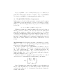
of the McEliece cryptosystem based on a t-error correcting (n, r, w)-QCMDPC code. The following parameters are proposed for a 80-bit security
level in [14]:
n0 = 2, n = 9602, r = 4801, w = 90, t = 84.
With these parameters a 4801-bit plaintext block is encoded into a
9602-bit codeword to which t = 84 errors are added. The parity-check
matrix H has constant row weight w = 90 and consists of n0 = 2 circulant
blocks, the redundant part Q of the generator matrix G consists of n0 −1 =
1 circulant block. The public key has a size of 4801-bit and the secret key
has a size of 9602-bit which can be compressed to 1440 bit since it is very
sparse. For a detailed discussion of the security of this scheme we refer
to [14].
Key-Generation Key-Generation is equal to generating a (n, r, w)-QCMDPC code with n = n0 r. The public key is the generator matrix G and
the secret key is the parity-check matrix H.
In order to generate a (n, r, w)-QC-MDPC code with n = n0 r, select the first rows h0 , . . . , h
n0 −1 of the n0 parity-check matrix blocks
P
0 −1
H0 , . . . , Hn0 −1 with weight ni=0
wt(hi ) = w uniformly at random. The
parity-check matrix blocks H0 , . . . , Hn0 −1 are then generated by r − 1
quasi-cyclic shifts of h0 , . . . , hn0 −1 . A horizontal concatenation forms the
parity-check matrix H = H0 , . . . , Hn0 −1 .
Generator matrix G = [Ik |Q] is computed from H in row reduced
echelon form by concatenating the identity matrix Ik and matrix
(Hn−1
· H0 )T
0 −1
(H −1 · H1 )T
n0 −1
.
Q=
···
−1
T
(Hn0 −1 · Hn0 −2 )
Since both matrices are quasi-cyclic, it suffices to store their first rows
instead of the full matrices. Note, when using a CCA2 conversion such
as [10, 16], G is allowed to be of systematic form without reducing the
security of the scheme.
Encryption Given a message m ∈ Fk2 , generate a random error vector
e ∈ Fn2 with wt(e) ≤ t and compute x = mG + e.
Decryption Given a ciphertext x ∈ Fn2 , compute mG ← ΨH (x) using
a t-error correcting (QC-)MDPC decoder ΨH . Since G is of systematic
form, plaintext m can be extracted from the first k positions of mG.
2.3
Decoding (QC-)MDPC Codes
Compared to the simple operations involved in encryption (i.e., a vectormatrix multiplication followed by an addition), decoding is the more complex operation. Several decoders have been proposed for (QC-)MDPC
codes in [3, 6, 8, 9, 14]. Here, we refer to the results obtained in [8] where
an optimized bit-flipping decoder based on [6] was identified as the most
suitable for the constrained computing environment of microcontrollers.
This decoder works as follows:
1. Compute the syndrome of the received ciphertext s = HxT .
2. Count the unsatisfied parity-checks for every ciphertext bit.
3. If the number of unsatisfied parity-checks for a ciphertext bit exceeds
a precomputed threshold, flip the ciphertext bit and update the syndrome.
4. If s = 0r , the codeword was decoded successfully. If s 6= 0r , go to Step
2. or abort after a defined maximum of iterations with a decoding
error.
The precomputed thresholds are derived from the code parameters as
proposed by [6].
3
Platform and Implementation Details
The STM32F4 Discovery board is equipped with a STM32F407 microcontroller which features a 32-bit ARM Cortex-M4F CPU with 1 Mbyte flash
memory, 192 Kbytes SRAM and a maximum clock frequency of 168 MHz.
It sells at roughly the same price of USD 5-10 as the AVR ATxmega256A3,
depending on the ordered quantity. It is based on a 32-bit instead of a 8-bit
architecture, can be clocked at higher frequencies, offers more flash and
SRAM storage, comes with DSP and floating point instructions, provides
communication interfaces such as CAN-, USB-/ and Ethernet controllers,
and has a built-in true random number generator (TRNG).
3.1
Implementing QC-MDPC McEliece for the STM32F407
Our implementations of the QC-MDPC McEliece cryptosystem for the
STM32F407 microcontroller cover key-generation, encryption, and decryption and aim for a reasonable time/memory trade-off.
Key-Generation Secret key generation starts by selecting a first row
candidate for Hn0 −1 with w/n0 set bits. The indexes in the range of
0 ≤ i ≤ r−1 at which bits are set are generated using the microcontroller’s
TRNG. Since r = 4801 is not a power of two, we sample error indexes ei
with dlog2 (r)e = 13 bits from the TRNG and only use them if ei ≤ r − 1
holds (i.e., rejection sampling).
exists. Hence, we
The public key computation requires that Hn−1
0 −1
apply the extended Euclidean algorithm to the first row candidate and
xr −1. If the inverse does not exist, we select a new first row candidate for
Hn0 −1 and repeat. If the inverse exists, the first row of Hn0 −1 is converted
into a sparse representation where w/n0 counters point to the positions
of set bits.
Next, we randomly select first rows for H0 , . . . , Hn0 −2 as described
for Hn0 −1 , convert and store them in their sparse representation, and
compute (Hn−1
Hi )T , 0 ≤ i ≤ n0 − 2. Note, since the matrices involved
0 −1
are quasi-cyclic, the result is quasi-cyclic as well. The resulting generator
matrix is not sparse and hence its first row is stored in full length.
Encryption Encryption is divided into encoding a message and adding
an error of weight t to the resulting codeword. To compute the redundant
part of the codeword, set bits in message m select rows of the generator
matrix G that have to be XORed. Starting from the first row of the generator matrix, we parse m bit-by-bit and decide whether or not to XOR
the current row to the redundant part. Then the next row is generated by
rotating it one bit to the right and the following message bit is processed.
This implementation approach was originally introduced in [8].
After computing the redundant part of the codeword, we append it
to the message and generate t random indexes at which we flip bits (i.e.,
the error addition) to transform the codeword into a ciphertext. We retrieve the required randomness directly from the microcontroller’s internal TRNG and again use rejection sampling, this time with dlog2 (n)e =
14-bit random numbers, to get a uniform distribution of error positions.
In Sect. 4.2 we describe the shortcomings of this implementation approach with regard to side-channel attacks and present countermeasures
in Sect. 5.1.
Decryption We implement the decoder as described in Sect. 2.3 to decrypt ciphertexts. First, the syndrome is computed, which is a similar
operation to encoding a message, except for the fact that the secret key is
stored in a sparse representation. The ciphertext is split into n0 parts that
correspond to the n0 blocks of the parity-check matrix. The ciphertext
blocks are processed in parallel bit-by-bit. If a ciphertext bit is set, the
corresponding row of the parity-check matrix is added to the syndrome
otherwise the syndrome remains unchanged. The following rows of the
parity-check matrix blocks are generated directly in the sparse representation by incrementing the counters.
If the computed syndrome s 6= 0r then we proceed by counting how
many parity-check equations are violated by a ciphertext bit. This is given
by the number of bits that are set in both the syndrome and the row of
the parity-check matrix block that corresponds to the ciphertext bit. If
the number of unsatisfied parity-check equations exceeds a precomputed
threshold bi , then the ciphertext bit is flipped and the row of the paritycheck matrix block is added to the syndrome.
If the syndrome is zero after a decoding iteration, decoding was successful. Otherwise we continue with further iterations until we reach a defined maximum upon which a decoding error is returned. In Sect. 4.3 we
describe the shortcomings of such an implementation with regard to sidechannel attacks and present corresponding countermeasures in Sect. 5.2.
4
Side-Channel Attacks
In the following we present power analysis attacks on the QC-MDPC
McEliece cryptosystem and describe how we modified two development
boards to allow meaningful power measurements. We used the freely available source code from [8] and compiled it for the Atmel AVR XMEGA-A1
Xplained board. The board features a 8-bit Atmel ATxmega128A1 microcontroller that can be clocked at a maximum frequency of 32 MHz and
which is technically equivalent to the ATxmega256A3 used in [8] except
for less flash and SRAM memory.
Power analysis attacks exploit the fact that when cryptographic operations are executed on a physical device, information about the processed
data and the executed instructions may be recovered from the consumed
electrical energy at different points in time. Simple power analysis (SPA)
attacks [11] are based on the idea that certain operations can be distinguished from each other by visual inspection or pattern recognition.
In this work we target and distinguish two side-channel attack (SCA)
scenarios: first a message recovery attack demonstrates that an on-chip
generated, secret message (e.g., a secret key for hybrid encryption) can
be easily obtained using its significant SCA-leakage during encryption.
Second, we investigate an SCA-attack on the leakage obtained during the
decryption operation to identify the private key.
4.1
Preparation of the Evaluation Boards
Since our goal is to observe power traces from the respective microcontroller, we modified the boards to allow unfiltered power measurements
as explained below. Note, we only modified external components on the
board, leaving the microcontrollers untouched.
For our measurements we use a PicoScope 5203 with two channels that
can obtain 500 MS/s for each channel sampling a bandwidth of 250 MHz.
One probe measures the power consumptions at an inserted measurement
resistor in the VDD path, the other probe is used to signal the beginning
and end of the cryptographic operation via an I/O pin of the respective
microcontroller (i.e., a trigger signal).
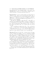
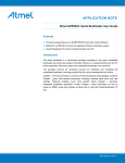
Atmel AVR XMEGA-A1 Xplained Board We removed all capacitors1 connected between the microcontroller’s VCC and GND and we
placed a 2.7 Ω resistor onto the power supply measurement header that
connects the board’s 3.3 V to the VCC pins of the microcontroller. Furthermore, we added three capacitors in parallel (100 µF, 100 nF, 10 nF)
right before our measurement resistor between the board’s 3.3 V and GND
to account for the removed capacitors. The modified AVR board is shown
in Fig. 1a.
STM32F4 Discovery Board Again, we removed all capacitors and
coils2 that are connected between the microcontroller’s VDD pins and
GND and placed a 2.7 Ω resistor onto the power supply measurement
header (IDD) that connects the board’s 3 V to the VDD pins of the microcontroller. Similarly, we added three capacitors in parallel (100 µF,
100 nF, 10 nF) right before our measurement resistor between the board’s
3 V and GND. The modified STM board is shown in Fig. 1b.
1
2
A total of ten 100nF capacitors (C102-C111) were removed, cf. [1].
One coil (L1) and 16 capacitors (C21-C26,C28-C37) were removed, cf. [19].
(a) Modified Atmel AVR XMEGA-A1 (b) Modified STM32F4 Discovery board
Xplained board with connected probes.
with connected probes.
Fig. 1: Measurement setups for our side-channel attacks.
4.2
Message Recovery Attack
Imagine an implementation in which the microcontroller generates a symmetric key to encrypt bulk data. The symmetric key is encrypted under
the public key of the intended receiver using asymmetric encryption. After exchanging the symmetric key, all communication is encrypted using
symmetric encryption for performance reasons.
If an attacker is able to perform a message recovery attack on the
asymmetric encryption, he is in possession of the symmetric (session-)
key which allows him to decrypt and forge symmetric ciphertexts until
the symmetric key is updated. Although this attack is not considered in
many SCA-related works, it has indeed a high practical relevance.
General Considerations Recall that when encrypting a message m
using QC-MDPC McEliece, the message is multiplied with the generator
matrix G and an error e is added to the result.
x=m·G+e
Message m selects rows of G which are accumulated to compute the
redundant part of the codeword. A message recovery attack is successful
if it is possible to detect if a certain row of G is accumulated or not, since
each accumulation can be directly mapped to a specific message bit.
The implementations under test perform QC-MDPC McEliece encryptions as follows: if a message bit is set, the corresponding row of G is
added to the redundant part, otherwise this step is skipped. Afterwards,
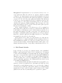
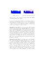
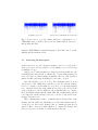
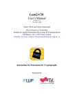
(a) Plain power trace.
(b) Power trace with marked message bits.
Fig. 2: Power trace of the encryption of a message starting with 0x8F402
on an ATxmega128A1 microcontroller.
the next row of G is generated and the process is repeated for the following message bit. The addition of one row of G to the redundant part
involves hundreds of load, xor, and store operations on both platforms.
Hence, our goal is to detect if this memory-intense operation is being
executed or not by inspection of the power trace.
Experiment on the AVR We recorded a power trace while encrypting
a randomly selected message that begins with 0x8F402 under a valid public key on an ATxmega128A1 microcontroller. The power trace as shown
in Fig. 2a allows to distinguish three reoccurring patterns. Two of these
patterns can be attributed to the performed or skipped row accumulation
from G, the third pattern corresponds to the generation of the next row
of G. Since the addition of a row of G corresponds to a set message bit,
the message that is encrypted can be read more or less directly from a
single power trace. We highlighted the different patterns and message bits
in Fig. 2b. Note, this attack is independent of the public key under which
the message is encrypted.
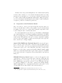
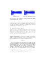
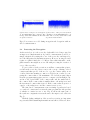
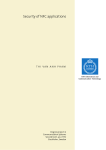
Experiment on the STM We repeated the attack on the STM32F407
microcontroller with the same message and public key as before. The
power trace is shown in Fig. 3a. Here, the patterns cannot be identified
as clear as on the ATxmega, but there is still an observable difference
in the power trace when a row of G is added to the redundant part
of the codeword. We highlighted the repeating pattern in Fig. 3b and
map the corresponding message bits to the power trace. Since in this
case there is no visible pattern for a message bit being zero, we use the
distance between two set message bits to determine how many zeros lie
in-between. This is done by cross-correlating the ”one”-pattern with the
(a) Plain power trace.
(b) Power trace with marked message bits.
Fig. 3: Power trace of the encryption of a message starting with 0x8F402
on an STM32F407 microcontroller.
recorded power trace and then dividing the distance from peak to peak
by the time it takes to skip one accumulation and generate the next row
of G. The exact duration of skipping one accumulation was obtained in
a profiling phase and only has to be done once.
4.3
Secret Key Recovery Attack
For the secret key recovery attack we assume that we are given a device
that decrypts some known ciphertext (knowledge of the corresponding
plaintext is not required) and that we are able to observe the power
consumption of the device during decryption. The goal is to recover the
secret key of the device from this information.
General Considerations Recall that at the beginning of a QC-MDPC
McEliece decryption, the syndrome s of the received ciphertext x is computed by multiplying the secret parity-check matrix H with xT .
s = H · xT
Since we are in a quasi-cyclic setting with n0 = 2, the first rows of the
two parity-check matrix blocks define the parity-check matrix. Following
the implementation in [8], each row of the secret key is stored using a
series of counters that point to the positions of set bits (here: 2 × 45
counters). To generate the next row, all counters are incremented by one.
If a counter exceeds r, it overflowed and has to be reset to zero (equal to
the carry bit of a rotated row).
Using SPA, at least two things should be observable from a power
trace that is recorded during syndrome computation:
1. A set ciphertext bit determines if a row of the secret key is being
added to the syndrome or not (similar to the message recovery attack
described before). But since the ciphertext usually is assumed to be
known to an attacker, recovering the ciphertext from a power trace is
not a meaningful attack.
2. Incrementing the counters that resemble (parts of) the secret key must
include an overflow check so that the counter is reset to zero if necessary. If it is possible to detect such an overflow, this reveals the
positions of set bits in the secret key and can be used for full key
recovery.
Both implementations store the position of the secret key bits in counters which are incremented to generate the next row of the quasi-cyclic
parity-check matrix blocks. The counters are ordered such that the last
counter stores the position of the most significant bit in the secret key.
When rotating a row of the secret key, there is a conditional branch depending on whether the last counter overflowed or not. If an overflow
occurred, all counter values are moved to the next counter and the first
counter is reset. This reduces the overall complexity to testing only the
last counter on an overflow condition.
We set the ciphertext to the all-zero vector in our experiments to
remove the influence of additions of secret key rows to the syndrome on
the power trace. Our attack still works if any other ciphertext is used and
would require to profile how long it takes to add a row of the secret key
to the syndrome which to be done only once. Another option would be
to just set bits at the end of the ciphertext, extract the secret key up to
this point and then find the remaining secret key bits by smart bruteforce (cf. [5]). Note that our attacks are independent of the implemented
decoding algorithm since we attack the syndrome computation that all
decoders share as a first step.
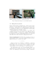
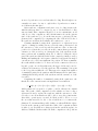
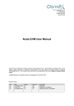
Experiment on the AVR A power trace of the first few rounds of the
syndrome computation is shown in Fig. 4a for a secret key starting with
(1101000 . . . )2 on the ATxmega128A1 microcontroller.
Two different repeating patterns can be distinguished in the power
trace. Our experiments showed that the first pattern occurs when the
device is checking whether the current ciphertext bit is set (which does not
happen when we set the ciphertext to the all-zero vector) and all counters
are incremented by one. The second pattern can only be detected in the
power trace if the highest counter overflowed. Hence, we can distinguish
if an overflow occurred or not. In case both patterns appear after each
(a) Plain power trace.
(b) Power trace with marked secret key bits.
Fig. 4: Power traces recorded during syndrome computation on an
ATxmega128A1 microcontroller. The secret key in this example starts
with (1101000 . . . )2 .
other, the highest counter overflowed. If only the first pattern appears,
the highest counter did not overflow.
An overflow means that the most significant bit of the secret key
was set. Since the secret key is rotated bit-by-bit, every bit of the secret
key will be the most-significant bit at some point during the syndrome
computation. Hence, it is possible to recover the secret key from a power
trace as shown in Fig. 4b where we highlight the two patterns and mark
the corresponding secret key bits.
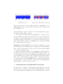
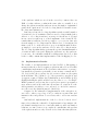
Experiment on the STM Fig. 5a shows the beginning of a power
trace that was recorded during syndrome computation on the STM32F407
microcontroller. The first two set bits of the secret key in this example
are at positions 4790 and 4741.
Again, two different patterns can be distinguished. Both patterns are
negative peaks in the power trace which differ in length compared to
reoccurring shorter peaks. Our experiments showed that the short peaks
appear when there is no counter overflow and the long peaks appear when
there is an overflow. Thus, it is again possible to map the power trace
to bits of the secret key. We highlight the two set bits at positions 4790
and 4741 in Fig. 5b. In between the two set bits there are 49 small peaks,
which translate to 49 zeros in the secret key.
5
Countermeasures and Implementation Results
In this section we describe countermeasures that mitigate the attacks
described in Sect. 4 and take other possible information leaks into account.
The countermeasures are implemented for the STM32F4 microcontroller
(a) Plain power trace.
(b) Power trace with marked secret key bits.
Fig. 5: Power traces recorded during syndrome computation on a
STM32F407 microcontroller. The secret key starts with set bits at positions 4790 and 4741.
using the ARM Thumb-2 assembly language to have full control over the
timings and the instruction flow.
5.1
Protecting the Encryption
As shown in Sect. 4.2, the encrypted message can be recovered from a
single power trace if it is possible to decide whether a row of G is being
accumulated or not.
Our proposed countermeasure is to always perform an addition to the
redundant part, independent of whether the corresponding message bit
is set. Of course we cannot simply accumulate all rows of the generator
matrix, as this would map all messages to the same codeword.
Since the addition of a row of G to the redundant part is done in
32-bit steps on the ARM microcontroller, we use the current message
bit mi to compute a 32-bit mask (0 − mi ). If mi = 0, then the mask is
zero, otherwise all 32 bits of the mask are set. Before the 32-bit blocks
of the current row of G are XORed to the redundant part, we compute
the logical AND of them with the mask. This either results in the current
row being added if the message bit is set, or in zero being added if the
message bit was not set.
This countermeasure leads to a runtime that is independent of the
message and the public key. Furthermore, as the same instructions are
executed for set and cleared message bits, a constant program flow is
achieved. Hence, it is not possible anymore to extract the message bits
from a power trace by means of a SPA attack (cf. Fig 6a).
(a) Power trace of the protected encryption
on the STM32F407 microcontroller. The
message starts with 0x8F402, the first bits
are given as reference.
(b) Power trace of the protected syndrome
computation on the STM32F407 microcontroller. The secret key starts with set bits
at positions 4790 and 4741.
Fig. 6: Power traces recorded during encryption and decryption with enabled countermeasures.
5.2
Protecting the Decryption
As shown in Sect. 4.3, the secret key leaks while it is being rotated in
an unprotected implementation. A possible countermeasure would be to
simply refrain from rotating the rows of the secret key and instead to
store the full parity-check matrix in memory. However, storing H would
require 2 × (4801 × 4801) bit = 5.5 Mbyte. Since this is infeasible on the
platform under investigation, we are left with protecting the rotation of
a row of the secret key.
To protect the secret key rotation, we still use counters that point to
set bits in the secret key, but we remove the concept of having ordered
counters and thus get rid of the need to copy the counter values on an
overflow. After incrementing a counter, we check for an overflow by comparing the counter value to the maximum r. We load the negative flag N
from the program status register, use it to compute a 32-bit mask (0 − N),
and store the logical AND of the counter value and the mask back to
the counter. If the counter value is smaller than r, the N flag is set and
the incremented counter value is stored. If the counter value is greater or
equal to r, the N flag is zero and the counter is reset to zero.
The introduced countermeasure removes timing dependencies based
on overflowed counters and executes the same program flow independent
of whether a counter is reset or not. Fig. 6b shows the same part of
the syndrome computation as was shown for the unprotected version in
Fig. 5b.
With the leakage mitigation of the secret key rotation one important
step towards SPA-resistant implementations was achieved. However, there
are more dependencies on secret data when decoding. Even though we are
currently not aware of a way to exploit these dependencies we want to
avoid them in the first place.
After syndrome computation and after every decoding iteration the
4801-bit syndrome has to be compared to zero to check whether decoding
was successful. This comparison should be done in constant-time, as an
early abort of the comparison could leak information about the current
state of the syndrome (e.g., about the first non-zero positions). We implemented the comparison by computing the OR of all 32-bit blocks of
the syndrome and then check whether the result is zero or not.
Counting unsatisfied parity-check equations for a ciphertext bit is
equal to counting how many bits are set at the same positions in both
the current row of the secret key and the syndrome. Since we know the
position of set bits in the secret key from the counters that represent the
current row of the secret key, we extract the bits of the syndrome at the
same positions and accumulate them. We do this by loading the 32-bit
part of the syndrome which holds the bit the counter is pointing to and by
shifting and masking the 32-bit part so that the bit in question is singled
out and moved to the least significant bit position. We then accumulate
the result which is either 0 or 1. As we use 16-bit counters for the secret
key and operate on a 32-bit architecture, the upper 11-bit can be used to
address a 32-bit memory cell of the syndrome. The remaining 5 bits point
to the bit position within the cell. This approach computes the number
of unsatisfied parity-check equations with an instruction flow (and hence
a timing) that is independent of the syndrome and the current row of the
secret key.
Comparing the number of unsatisfied parity-check equations to the
threshold for the current iteration is implemented as a function
ge u32(x, y) = (1 ⊕ ((x ⊕ ((x ⊕ y)|((x − y) ⊕ y))) >> 31))
which returns 1 if x is greater or equal to y and 0 otherwise in constant
time. The result of this comparison decides whether we have to flip a
ciphertext bit and to update the syndrome with the current row of the
secret key or not. If an attacker would be able to trace the points in time
when these operations are executed, he likely would be able to recover
the error that was added to the codeword and hence to reconstruct the
plaintext. To circumvent this possible leakage, we always XOR the ciphertext bit at the current position with the result of the comparison which
is either 1 or 0. In addition we always perform the syndrome update, in
which we XOR the bit that resulted from the comparison to the positions
of the syndrome which are stored in the secret key counters. Since an
XOR of a value with zero results in the same value, we actually do not
change the ciphertext and the syndrome in case the number of unsatisfied
parity-check equations is below the decoding threshold but still execute
the exact same instructions.
Last but not least, the decoding algorithm can take a variable number
of iterations before it terminates. In most cases decoding is finished after
either 2 or 3 decoding iterations (on average 2.4 iterations, cf. [8]) and
in rare cases it requires up to a fixed maximum of five iterations. We
remark that it is unclear yet if it is possible to recover secret data only
from the number of decoding iterations. This needs to be investigated in
future work. To be on the safe side we propose an implementation where
we simply do not test the syndrome for zero after a decoding iteration.
The decoding algorithm always performs the specified maximum number
of iterations where it stops modifying the ciphertext once the syndrome
becomes zero. In combination with the techniques introduced above this
leads to a fully constant time implementation of the bit-flipping decoder.
5.3
Implementation Results
The results of our implementations are listed in Tab. 1. Encrypting a
messages takes 42 ms and decrypting a ciphertext takes 558 ms in a fully
constant-time implementation. Key-generation takes 884 ms on average,
but usually key-generation performance is not an issue on small embedded devices since they generate few (if even more than one) key-pairs
in their lifetime. The combined code of key-generation, encryption, and
decryption, requires 5.7 kByte (0.6%) flash memory and 2.7 kByte (1.4%)
SRAM, including the public and the secret key. Since w << r for all QCMDPC parameter sets, storing the secret key in a sparse representation
saves memory and at the same time allows fast row rotations. For the
80-bit parameter set with n0 = 2 we only need w = 90 16-bit counters to
store the secret key (1440 bit instead of 9602 bit).
Compared to the vulnerable C implementation of the encryption, we
were able to achieve a speed up of 50%, to make its execution time and
instruction flow independent of secret data, and to add a true random
error.
Our hardened implementations of the decoder are between 1.1-2.5
times slower than the vulnerable C implementation but mitigate the
side-channel attacks from Sect. 4 and take further possible information
leaks into account. Version ct3 is completely constant-time independent
of the ciphertext and secret key. Version ct2 accelerates the first syndrome
Table 1: Results of our QC-MDPC microcontroller implementations. The
compiler optimization level was set to -O2. A combined implementation of
key generation, encryption, and decryption occupies 5.7 kByte flash and
2.7 kByte SRAM.
Scheme
Platform
Cycles/Op
Time
This work [enc]
This work [dec]
STM32F407
STM32F407
16,771,239
37,171,833
100 ms
221 ms
STM32F407
STM32F407
STM32F407
STM32F407
7,018,493
42,129,589
85,571,555
93,745,754
42 ms
251 ms
509 ms
558 ms
This work [keygen]
STM32F407
148,576,008
884 ms
McEliece [enc] [8]
McEliece [dec] [8]
ATxmega256
ATxmega256
26,767,463
86,874,388
836 ms
2,71 s
This
This
This
This
work
work
work
work
[enc,
[dec,
[dec,
[dec,
ct]
ct1 ]
ct2 ]
ct3 ]
computation by skipping accumulations if ciphertext bits are not set. As
discussed in Sect. 4.3, the computation only depends on set bits in the
ciphertext (selecting which rows of the parity-check matrix are XORed)
which is usually assumed to be known to an attacker anyways. Version
ct1 of the decoder tests the syndrome for zero after each decoding iteration and exits if decoding was successful before reaching the maximum
iterations.
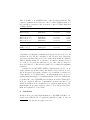
Compared to the QC-MDPC McEliece implementation in [8], our encryption function is 20 times faster and includes a true random error addition. Decryption performance is improved to a much more realistic 251558 ms instead of 2.7 s. Furthermore, our implementations are protected
against timing and simple power analysis attacks. Please note that the microarchitecture of the STM32F407 used in this work and the ATxmega256
in [8] are completely different – but similarly expensive in terms of cost
(which is usually a most relevant factor for practical applications). The
implementations are made available online to allow independent refinement and verification of our results3 .
6
Conclusion
In this work we presented implementations of QC-MDPC McEliece encryption providing 80 bits of equivalent symmetric security on low-cost
3
http://www.sha.rub.de/research/projects/code/
ARM Cortex-M4-based microcontrollers with a reasonable performance
for encryption and decryption, respectively. We demonstrated side-channel
attacks on a straightforward implementation of this scheme and finally
proposed timing- and instruction-invariant coding strategies and countermeasures to strengthen it against timing attacks and simple power
analysis. Future work includes differential power analysis (DPA) as well
as investigations with respect to fault-injection attacks.
Acknowledgments
This work is supported by grant 01ME12025 SecMobil of the German
Federal Ministry of Economics and Technology.
References
1. Atmel. Atmel AVR1924: XMEGA A1 Xplained Hardware User Guide. http:
//www.atmel.com/Images/AVR1924.zip, 2010.
2. R. Avanzi, S. Hoerder, D. Page, and M. Tunstall. Side-channel attacks on the
McEliece and Niederreiter public-key cryptosystems. Journal of Cryptographic
Engineering, 1(4):271–281, 2011.
3. E. Berlekamp, R. McEliece, and H. van Tilborg. On the Inherent Intractability of
Certain Coding Problems (Corresp.). Information Theory, IEEE Transactions on,
24(3):384 – 386, may 1978.
4. F. Biasi, P. Barreto, R. Misoczki, and W. Ruggiero. Scaling efficient code-based
cryptosystems for embedded platforms. Journal of Cryptographic Engineering,
pages 1–12, 2014.
5. C. Chen, T. Eisenbarth, I. von Maurich, and R. Steinwandt. Differential
Power Analysis of a McEliece Cryptosystem. Cryptology ePrint Archive, Report
2014/534, 2014. http://eprint.iacr.org/.
6. R. Gallager. Low-density Parity-check Codes. Information Theory, IRE Transactions on, 8(1):21–28, 1962.
7. S. Heyse, A. Moradi, and C. Paar. Practical Power Analysis Attacks on Software
Implementations of McEliece. In N. Sendrier, editor, Post-Quantum Cryptography,
volume 6061 of Lecture Notes in Computer Science, pages 108–125. Springer Berlin
Heidelberg, 2010.
8. S. Heyse, I. von Maurich, and T. Güneysu. Smaller Keys for Code-Based Cryptography: QC-MDPC McEliece Implementations on Embedded Devices. In G. Bertoni
and J.-S. Coron, editors, CHES, volume 8086 of Lecture Notes in Computer Science, pages 273–292. Springer, 2013.
9. W. C. Huffman and V. Pless. Fundamentals of Error-Correcting Codes, 2010.
10. K. Kobara and H. Imai. Semantically Secure McEliece Public-Key CryptosystemsConversions for McEliece. In Proceedings of the 4th International Workshop on
Practice and Theory in Public Key Cryptography: Public Key Cryptography, PKC
’01, pages 19–35, London, UK, 2001. Springer-Verlag.
11. P. C. Kocher, J. Jaffe, and B. Jun. Differential Power Analysis. In M. J. Wiener,
editor, CRYPTO, volume 1666 of Lecture Notes in Computer Science, pages 388–
397. Springer, 1999.
12. R. J. McEliece. A Public-Key Cryptosystem Based On Algebraic Coding Theory.
Deep Space Network Progress Report, 44:114–116, Jan. 1978.
13. R. Misoczki, J.-P. Tillich, N. Sendrier, and P. S. L. M. Barreto. MDPC-McEliece:
New McEliece Variants from Moderate Density Parity-Check Codes. Cryptology
ePrint Archive, Report 2012/409, 2012. http://eprint.iacr.org/.
14. R. Misoczki, J.-P. Tillich, N. Sendrier, and P. S. L. M. Barreto. MDPC-McEliece:
New McEliece variants from Moderate Density Parity-Check codes. In ISIT, pages
2069–2073. IEEE, 2013.
15. H. Niederreiter. Knapsack-type cryptosystems and algebraic coding theory. Problems Control Inform. Theory/Problemy Upravlen. Teor. Inform., 15(2):159–166,
1986.
16. R. Nojima, H. Imai, K. Kobara, and K. Morozov. Semantic security for the
McEliece cryptosystem without random oracles. Des. Codes Cryptography, 49(13):289–305, 2008.
17. P. W. Shor. Polynomial-Time Algorithms for Prime Factorization and Discrete
Logarithms On a Quantum Computer. SIAM J. Comput., 26(5):1484–1509, 1997.
18. A. Shoufan, F. Strenzke, H. Molter, and M. Stttinger. A Timing Attack against
Patterson Algorithm in the McEliece PKC. In D. Lee and S. Hong, editors, Information, Security and Cryptology – ICISC 2009, volume 5984 of Lecture Notes in
Computer Science, pages 161–175. Springer Berlin Heidelberg, 2010.
19. STMicroelectronics. UM1472 User manual - Discovery kit for STM32F407/417
lines. http://www.st.com/st-web-ui/static/active/en/resource/technical/
document/user_manual/DM00039084.pdf, 2014.
20. F. Strenzke. A Timing Attack against the Secret Permutation in the McEliece
PKC. In N. Sendrier, editor, Post-Quantum Cryptography, volume 6061 of Lecture
Notes in Computer Science, pages 95–107. Springer Berlin Heidelberg, 2010.
21. F. Strenzke, E. Tews, H. Molter, R. Overbeck, and A. Shoufan. Side Channels in the
McEliece PKC. In J. Buchmann and J. Ding, editors, Post-Quantum Cryptography,
volume 5299 of Lecture Notes in Computer Science, pages 216–229. Springer Berlin
Heidelberg, 2008.
22. I. von Maurich and T. Güneysu. Lightweight code-based cryptography: QC-MDPC
McEliece encryption on reconfigurable devices. In DATE, pages 1–6. IEEE, 2014.